
Расшифровка символов на приборной панели.

Предлагаем нашим читателям самый полный список значков-символов, которые могут загораться на приборной панели автомобилей. Современные автомобили имеют множество датчиков и сенсоров, а также и электронное управление двигателем. Вся информация с датчиков стекается в бортовой компьютер автомашины. В случае какой-либо ошибки, поломки или другой необходимости сообщить водителю важную информацию, автопроизводители предусмотрели на приборной панели большое количество сигнальных символов и надписей, которые при определенных условиях тут-же загораются. К всеобщему сожалению, такое большое разнообразие сигнальных символов на приборной панели машины путает многих наших водителей, а иногда даже просто пугает. Мы собрали для вас дорогие читатели более 150 сигнальных значков-символов, которые встречаются сегодня в более-чем в 2000 автомобилях. В данный обзор включены 30 автомобильных марок машин.
Почему значки-символы на приборной панели разного цвета?

Производители автомобилей предусмотрели в них несколько видов таких надписей и символов на приборной панели, разделив их по цвету (цветовой гамме). Например, если вы видите на приборке (на приборной панели) не красный значок-символ, а например зеленый или синего цвета, то ваша автомашина скорее всего работает по-прежнему в нормальном режиме и Вы спокойно можете продолжать движение. Но тем не менее, вы ни в коем случае не должны игнорировать появление любого предупреждающего сигнала на приборной панели.
Если на данной панели появился красный значок-символ, то электронная система автомобиля заранее предупреждает вас о потенциальной серьезной проблеме.
Если на приборной панели появился желтый или оранжевый значок-символ, то автомобиль также предупреждает вас о том, что вашему автомобилю возможно требуется техническое обслуживание, или диагностика, или ремонт.
Обратите друзья ваше внимание на тот момент, когда значок-символ мигает, в таком случае Вы не должны затягивать на долго с поездкой в автотехнический центр.
И так уважаемые читатели приступим и начнем наши разъяснения с наиболее важных и серьезных значков-символов на приборной панели, а далее в порядке убывания и по их значимости (важности) мы продолжим постепенно описывать данные значения значков-символов находящихся на приборных панелях автомобилей.
Предупреждающие символы — Серьезные предупреждения.

Если вы видите на приборной панели какой-либо из ниже указанных следующих символов, ни в коем случае не игнорируйте данное предупреждение. Немедленно остановитесь, заглушите двигатель и далее срочно обратитесь в автотехнический центр или автосервис.
Внимание! Нижеуказанные предупреждающие символы (значки) не должны быть Вами проигнорированны. В противном случае ваш автомобиль в любой момент может быть серьезно поврежден.
 |
Предупреждающие индикаторы тормозной системы. |
 |
 |
Система охлаждения двигателя, индикатор температуры. |
 |
 |
Уровень масла в двигателе или давление масла. |
 |
 |
Датчик индикатора уровня масла в двигателе. |
 |
 |
Индикатор зарядки аккумулятора. |
 |
Обычные и общие значки-символы на приборной панели.

Следующие символы на приборной панели автомобилей предназначены для того, чтобы предупреждать водителя о плановых потребностях их автомашины и напоминать им о том, что необходимо в этом случае сделать. Например, данный вид значков-символов предупреждает Вас о низком уровне стеклоомывающей жидкости или о том, что вы не закрыли за собой плотно дверь. Этот вид значков-символов может загораться как на самой приборной панели, так и на информационно-развлекательной системе автомобиля (на экране по центру консоли).
 |
Напоминание о не пристегнутом ремне безопасности |
||
 |
Символ дверей автомобиля. Может предупреждать о не закрытой двери. |
 |
|
 |
Уровень топлива, индикатор низкого уровня топлива. |
||
 |
Значок жидкости стеклоомывателя. Низкий уровень жидкости. |
||
 |
Контроль давления в шинах. Если загорелся, то в шинах упало давление. |
 |
|
 |
Check Engine — Чек двигателя. Ошибка работы двигателя. Подробнее… |
 |
 |
 |
Напоминание о необходимости технического обслуживания автомобиля. |
 |
 |
Осветительные значки и символы в автомобилях.

Ниже представлены все индикаторы на приборной панели, которые связаны с системой освещения вашего автомобиля. Многие значки-символы многие из нас наверняка видели в своей автомашине. Большинство из них загораются зеленым или синим цветом.
 |
Значок включенных фар. |
||
 |
Символы неисправности фар. |
 |
 |
 |
Значок включенного дальнего света. |
||
 |
Включена автоматическая система ближнего света. Датчик света. |
||
 |
Автоматическая система управления дальним светом. |
||
 |
Значок о выравнивании фар. Если горит, то необходима диагностика. |
 |
|
 |
Неисправность поворотников. |
||
 |
Индикатор дневных световых огней. |
||
|
|
Неисправность лампочки в задних фарах. |
||
 |
Символ габаритных огней. |
||
 |
Символ задних противотуманных фар. |
||
 |
Стрелки, указывающие на работу поворотников или включенную аварийную сигнализацию. |

Информационные дисплеи на приборной панели для технических сообщений и предупреждений.


В последние годы во всех современных автомобилях производители стали устанавливать в приборную панель информационные дисплеи, которые созданы в первую очередь для того, чтобы сообщать водителю более подробную информацию об автомобиле, а также о многих работающих системах в автомобиле. Как правило этот информационный экран установлен в машине по центру приборной панели.
На авторынке в наше время существует огромное количество автомобилей, которые оснащены подобным экраном, данный экран способен выводить на дисплей различную информацию об ошибках, различные предупреждения и т.п. сигналы.
Символы неисправности систем автомобиля и предупреждения о безопасности.

Если Вы увидите на приборной панели указанные значки-символы, то обратитесь друзья напрямую к дилеру или в автосервис как можно быстрее. Внимание! Символы (значки) указаны в порядке их важности, от серьезных к менее серьезным предупреждениям.
 |
Значок загорается вместе с появлением предупреждения-сообщения на приборной панели. В Европейских автомобилях желтый знак(цвет) означает неисправность системы контроля устойчивости. |
 |
|
 |
Ошибка подушки безопасности. |
 |
|
 |
Индикатор не активных боковых подушек безопасности. |
||
 |
Предупреждение о не пристегнутых ремнях безопасности водителя и переднего пассажира. |
||
 |
Предупреждение о непрестегнутых ремнях безопасности задних пассажиров. |
||
 |
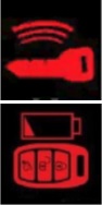
Индикация сигнализации автомобиля / Значок Иммобилайзера. |
 |
 |
 |
Ошибка коробки передач. Неисправность АКПП. |
 |
|
 |
Предупреждение о перегреве АКПП или системы привода. |
||
 |
Перегрев коробки передач или проблема со сцеплением. |
||
 |
Слишком большая температура масла в коробке передач. |
||
 |
Неисправность усилителя рулевого управления. |
||
 |
Стояночный тормоз (ручник). |
 |
|
 |
Низкий уровень тормозной жидкости. |
||
 |
Антиблокировочная тормозная система. |
 |
 |
 |
Символ о износе тормозных колодок. |
||
 |
Проблемы с электронным управлением тормозной системы. |
||
 |
Неисправность электрического стояночного тормоза (ручник). |
||
 |
Предупреждение о необходимости нажать педаль тормоза перед запуском двигателя или перед переключением коробки передач. |
 |
|
 |
Система контроля за давлением в шинах. При появлении проверьте давление. |
 |
|
 |
Check Engine — Чек двигателя. Подробнее здесь… |
 |
 |
 |
Проверьте электрооборудование двигателя. |
||
|
|
Снижение мощности двигателя. |
||
 |
Неисправность двигателя. |
||
 |
Лямбда-зонд. Индикатор неисправности датчика кислорода. |
||
 |
Не закрыт бензобак. Воздух в топливной системе. |
||
 |
Символ, указывающий на наличие информационного сообщения в системе. |
||
 |
Необходимость ознакомиться с руководством по эксплуатации автомобиля. |
||
 |
Перегрев или неисправность катализатора. |
||
 |
Низкий уровень охлаждающей жидкости. |
 |
 |
 |
Проблемы с охлаждением двигателя / Низкий уровень охлаждающей жидкости. |
 |
|
 |
Проблема с электронной системой управления дроссельной заслонкой. |
||
 |
Индикатор загрязнения воздушного фильтра. |

Значки-символы на приборной панели систем помощи и безопасности.

Новые автомобили кроме стандартных пиктограмм на приборной панели имеют множество новых неизвестных многим символов, которые относятся к индикации многих функций систем безопасности и помощи водителю.
 |
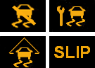
Индикация системы контроля тяги. |
 |
|
 |
Низкая скорость автомобиля / Система помощи спуска с горы. |
 |
|
 |
Режим движение по бездорожью на маленькой скорости. |
||
 |
Система стабилизации выключена. |
||
 |
Различные индикаторы контроля стабильности и устойчивости — Выключена. |
 |
|
 |
Система динамической стабилизации выключена. |
||
 |
Неисправность антипробуксовочной системы / Неисправность электронной тормозной системы. |
||
 |
Система предупреждения о заносе автомобиля / Система контроля устойчивости. |
 |
 |
Специальные и дополнительные значки-символы на приборной панели автомобилей.

Все символы и индикаторы которые мы внесли в эту группу, напрямую связаны с особыми и новыми технологическими функциями в современных автомобилях. Часть символов из этой группы в случае индикации зеленым цветом означают следующее, что в данный момент времени они активны. Другие же символы при появлении их на приборной панели сообщают водителю о том, что появилась проблема с работой той или иной функции. Как правило при таких проблемах высвечиваются либо желтые, либо красные значки-символы.
 |
Неисправность крыши в кабриолете. |
||
 |
Индикация обнаружения бесконтактного ключа. |
 |
 |
 |
Ключ не обнаружен. |
 |
|
|
|
Индикатор предупреждения отрицательной температуры на улице. |
||
 |
Предупреждение водителю о необходимости отдыха. |
 |
|
 |
Система предупреждения об опасном сближении автомобиля с другими ТС. |
||
 |
Индикация легкого доступа в автомобиль. |
||
 |
Индикация включенного круиз-контроля. |
||
 |
Значок включенного круиз-контроля. |
||
 |
Активный адаптивный круиз-контроль. |
 |
 |
 |
Проблемы с круиз-контролем. |
 |
 |
 |
Автоматический ограничитель скорости (ASL). |
||
 |
Система контроля полосы и безопасность проезда перекрестков. |
 |
 |
 |
Система безопасности столкновения выключена или неисправна. |
 |
|
 |
Предупреждение об опасности столкновения в задней части машины. |
 |
|
 |
Система оповещения об опасности столкновения в передней части машины. |
||
 |
Предупреждение о пешеходе на дороге. |
 |
|
 |
Система предупреждения о нахождении автомобиля в мертвой зоне. |
 |
|
 |
Система помощи при парковке. |
 |
|
 |
Система предупреждения о нажатой педали тормоза. |
||
 |
Включена система режима работы подвески СПОРТ. |
||
 |
Режим буксировки / Индикация наличия прицепа. |
 |
|
Различные символы экономии топлива: |
|||
 |
Функция запуска системы стоп-старт. |
 |
 |
 |
Неисправность системы старт-стоп. |
 |
|
 |
Включен режим экономии топлива. |
||
 |
Включен режим экономии топлива. |
||
 |
Предупреждение о необходимости перейти на другую передачу (МКПП). |
 |
|
 |
Индикация спорт-режима автомобиля. |
||
Различные значки в полноприводных автомобилях: |
|||
 |
Включен полноприводный режим (AWD). |
||
 |
Привод на все четыре колеса. |
 |
|
 |
Блокировка дифференциала. |
 |
 |
 |
Блокировка заднего дифференциала. |
 |
|
 |
Неисправность полного привода. |
 |
|
 |
Система помощи спуска с горы или система безопасности при движении в гору. |
 |

Символы и значки на приборной панели гибридных автомобилей.

За последние несколько лет в авто-мире появилось немало гибридных и электрических автомобилей, которые имеют совсем новые специфические значки-символы на приборной панели. В большей своей части эти специальные символы в гибридных автомобилях обозначают следующее, а именно, как работает гибридная система и в каком именно режиме она действует. Внимание! Мигающий значок на приборной панели гибридной машины, как правило означает какую-либо проблему с самим автомобилем. В этом случае Вы обязательно должны обратиться в автотехнический центр к дилеру.
 |
Неисправность аккумулятора. |
 |
 |
Предупреждающий индикатор электронной системы. |
|
 |
Высокое напряжение аккумуляторной батареи. |
|
 |
Индикатор низкого напряжения аккумуляторной батареи. |
|
 |
Мощность ограничена. |
|
 |
Индикатор зарядки аккумуляторной батареи. |
 |
 |
Режим тяги на одном электродвигателе. |
|
 |
Готовность гибридной установки. |
 |
 |
Режим тяги на одном электродвигателе. |
|
 |
Система внешней звуковой системы для предупреждения пешеходов о движении электроавтомобиля. Неисправность. |
 |
Символы (значки), используемые в дизельных автомобилях.

Ниже нами представлены значки-символы приборной панели, которые используются в дизельных автомобилях.
 |
Индикация работы свечи накаливания. |
||
 |
Предупреждение о сажевом фильтре. |
 |
|
 |
Предупреждение о проблемах с выхлопом из-за сажевого фильтра. |
 |
|
 |
Вода в топливной системе. |
 |
 |
Количество систем в автомобилях постоянно растет, развиваются новые технологии, ассистенты и автопилоты. Автопроизводители часто внедряют в свои автомобили схожие технологии, но под собственными названиями, поэтому проблема с одной и той же системой может отображаться на приборной панели разными значками. В этом материале мы собрали каталог индикаторов (значков) на приборных панелях автомобилей с подробными описаниями и расшифровками их обозначений.
Как правило, значки зеленого цвета обозначают активацию какой-то автомобильной системы, желтые и красные говорят о неисправностях. Значки красного цвета обычно говорят о более серьёзных проблемах, либо могут означать критические неисправности, при которых использование автомобиля недопустимо.
Значки с критическими неисправностями
Восклицательный знак в круге или надпись Brake

Включен ручной тормоз или неполадки с тормозной системой (низкий уровень тормозной жидкости, чрезмерный износ колодок и другое), или неисправность одного из датчиков.
Синий или красный термометр (градусник)

Проблемы с температурой двигателя. Красный термометр означает перегрев — необходимо срочно заглушить двигатель, синий термометр означает низкую температуру двигателя — перед началом движения стоит прогреть мотор. Также данные ошибки могут возникать из-за неисправных температурных датчиков.
Масленка с каплей (чайник)
![]()
Обычно обозначает низкое давление масла в двигателе или неисправность датчика давления масла. Иногда также этот значок значит низкий уровень масла, хотя для последнего чаще встречается другое обозначение (смотрите ниже).
Масленка с волнами или надписями Oil level, Min, Sensor

Низкий уровень масла в двигателе или неисправность датчика уровня масла. Проверьте масляный щуп. Некоторые из этих значков также могут обозначать низкое давление масла в моторе.
Аккумулятор или аккумулятор с надписью Main

Если горит лампа аккумулятора это означает низкий заряд батареи, отсутствие зарядки аккумулятора в следствие неисправности генератора или проблемы в его цепи. На гибридных автомобилях чаще встречается с надписью Main.
Двигатель с надписью STOP или просто надпись STOP

Такая сигнальная лампа означает необходимость экстренной остановки двигателя. На автомобилях ВАЗ обычно означает низкий уровень тормозной жидкости или масла. Появление такого значка может сопровождаться звуковым сигналом. Движение лучше прекратить.
Неисправности систем безопасности
Надпись Airbag, SRS, «беременный мужик»

Ошибка по SRS (Supplemental Restraint System) — вспомогательной удерживающей системе, относится к системам пассивной безопасности. Лампочка SRS горит если есть проблема с подушками безопасности или в их цепи. Автомобилисты именуют первый значок «беременный мужик», эта ошибка часто возникает из-за окисления контактов в цепи к подушкам безопасности, на некоторых авто это «болячка».
Легковой автомобиль и волны вокруг

Ошибка системы предупреждения столкновений. Обычно используется в автомобилях с системами автономного управления, укомплектованных камерами и/или радарами.
Человек с ремнем, надпись Side Airbag Off

Обозначает отключение подушки безопасности переднего пассажира. Это может быть признаком неисправности в цепи, проблемы с подушкой безопасности, либо же попросту подушка переднего пассажира отключена — современные авто имеют такую функцию — с отключенной подушкой можно перевозить детей спереди в детских креслах. Переключатель обычно находится в правом торце торпедо.
Надпись ABS, Antilock, значок скользящего автомобиля

Все эти индикаторы обозначают проблему с антиблокировочной системой ABS. Обычно датчики этой системы есть в каждом колесе и неисправность любого из сенсоров будет вызывать такую ошибку. Требуется диагностика.
Восклицательный знак в красном треугольнике
![]()
Открыта одна из дверей, багажник или капот, не пристегнут ремнем безопасности водитель или пассажиры или иные нештатные ситуации. Индикатор может сочетаться с писком зуммера.
Восклицательный знак в оранжевом треугольнике

Проблемы в электронной системе контроля устойчивости автомобиля (ESP).
Надпись RSCA OFF
![]()
Отключены боковые шторки безопасности, срабатывающие при переворачивании автомобиля. Обычно кнопкой с возможностью отключения данной системы комплектуются внедорожники — при сильных кренах кузова шторки могут сработать.
Надпись PCS или машина с ключом

Отключена система предупреждения столкновений или предаварийной безопасности — PCS (Pre-collision system или Pre-crash system).
Надпись EPB
![]()
Сигнальный индикатор системы электронного стояночного тормоза (EPB)
Значок ключа или машины с замком

Активирована штатная сигнализация или иммобилайзер. После распознавания ключа должна потухнуть. Если этого не происходит ключ не распознается или есть иная проблема.
Красный круг
![]()
Красный круг или мяч означает активацию противоугонной системы в результате которой был заблокирован двигатель. После распознавания ключа должна потухнуть, если этого не происходит — возможно есть проблема с иммобилайзером или ключ не распознается.
Ошибки и индикаторы автоматической коробки передач
Восклицательный знак в шестеренке красного или желтого цвета

Ошибка с шестеренкой желтого цвета означает проблемы с автоматической коробкой передач и ее работе в аварийном режиме. Красная шестеренка может также означать проблемы с силовым агрегатом.
Надписи AT или A/T Oil Temp, гаечный ключ, термометр в шестеренке

Включение одного из данных индикаторов означает наличие проблем с автоматической трансмиссией — AT (Automatic Transmission). Чаще всего это означает перегрев масла в коробке передач или неисправность температурного датчика. Желтые лампочки предупреждают о наличии проблем, при загорании красной лучше прекратить движение. Также такие лампочки могут означать проблемы с блоком управления коробкой передач.
Ошибки P-Shift; A/T P; P
Такие значки на панели приборов означают аварийный (или сервисный) режим автоматической коробки передач. Могут означать как неисправность, так и перевод коробки передач в сервисный (нейтральный) режим для обслуживания на СТО (в автомобилях предусмотрена кнопка для включения этого режима).
Ось автомобиля с рычагами

Может означать различные проблемы с узлами трансмиссии, в том числе перегрев коробки передач, проблемы со сцеплением и другое. Точное значение для конкретного автомобиля читайте в руководстве по эксплуатации.
Коробка передач и надпись Auto
![]()
Такая лампочка может загореться только на автомобилях с автоматической коробкой передач. Означает наличие проблем с АКПП — низкий уровень масла, высокая температура, проблемы с блоком управления АКПП или датчиками.
Стрелка вверх
![]()
Подсказывает о необходимости сменить передачу на более высокую.
Надпись CVT
![]()
Ошибка по бесступенчатой коробке передач или вариатору CVT (Continuously Variable Transmission).
Надпись 2nd STRT
![]()
В некоторых автомобилях с автоматической коробкой передач есть функция трогания с места на второй передаче, которая помогает начать движение в сложных условиях (гололед). Подсветка этой лампочки означает активацию системы.
Ботинок в кружочке со скобками
![]()
Этот индикатор бывает на автомобилях с автоматической трансмиссией. Напоминает о необходимости нажать на педаль тормоза, прежде чем включить передачу.
Иконка автомобиля с гаечным ключом
![]()
Может обозначать проблемы с двигателем, трансмиссией или иммобилайзером. Конкретно что обозначает эта лампочка в вашем автомобили смотрите в руководстве по его эксплуатации.
Надпись PWR
![]()
Эта лампочка горит когда активирован режим «Power» в автомобиле с автоматической коробкой передач. В этом режиме переключение на более высокую передачу происходит на более высоких оборотах чем обычно с целью получить максимальную мощность.
Надпись O/D Off или Over Drive Off
![]()
Эта лампочка сообщает об отключении системы OverDrive. Есть только на автомобилях с автоматической коробкой передач, при отключении этой системы машина не будет переходить на повышенную передачу для экономии топлива. При наличии системы OverDrive должна быть и кнопка ее отключения.
Прочие ошибки на панели приборов
Волны в круге и скобки с двух сторон
![]()
Индикатор обозначает низкий уровень тормозной жидкости.
Руль с восклицательным знаком
![]()
Проблемы с системой рулевого управления с электроусилителем (EPS).
Красная буква P в кружочке со скобками
![]()
Включен ручной (стояночный) тормоз. На новых автомобилях «ручной» тормоз автоматически включается при остановке автомобиля.
Желтый восклицательный знак в кружочке со скобками
![]()
Проблема с системой распределения тормозных усилий (Electronic brakeforce distribution, EBD). Это более развитая система чем ABS и она действует постоянно, а не только при экстренном торможении.
Желтый круг с прерывистыми скобками
![]()
Индикатор износа колодок. Информация поступает от датчиков-расходников, которые постепенно стирается вместе с колодками, пока не разорвется электрическая цепь — в этот момент и загорается такая лампочка. Нужно заменить колодки или проверить датчики.
Молния в кружочке со скобками
![]()
Система обнаружила проблему с электрическим стояночным тормозом.
Индикатор низкого давления шин

Такие индикаторы обычно используются у автомобилей, оборудованных датчиками давления шин. Сообщают о низком давлении в шинах (падение давления на более чем 25% от номинального).
Иконка двигателя с надписью Check, надписи Check Engine, EPC

Такие ошибки обозначают наличие проблем с двигателем. Лампочка горит только при заведенном двигателе. Это могут быть неисправности датчиков, плохая топливо-воздушная смесь и так далее. Check Engine с английского переводится «проверьте двигатель». Ошибка может сопровождаться неровной работой мотора, плохой тягой, рывками при движении и так далее. Эту ошибку автомобилисты часто в шутку называют «джеки чан». Надпись EPC (Electronic Power Control) можно увидеть на автомобилях концерна Volkswagen Group, означает проблемы с зажиганием или управлением двигателем.
Надпись ENG A-Stop

Такой индикатор можно увидеть на автомобилях с системой старт-стоп. Зеленый значок горит при заглушенном двигателей, желтый сигнализирует о неисправностях с этой системой.
Двигатель со стрелкой вниз
![]()
Индикатор плохой тяги мотора (снижение его мощности).
Значок с греческой буквой λ (лямбда) в треугольнике
![]()
Система обнаружила неисправности в датчике-кислорода (так называемый лямбда-зонд). Таких датчиков в автомобиле может быть несколько, они участвуют в регулировке топливовоздушной смеси. При неисправности может быть повышенный расход топлива или плохая тяга.
Индикатор катализатора
![]()
Проблемы с нейтралитическим катализатором системы выпуска отработанных газов — перегрев или иная неисправность.
Крышка бензобака или надпись Check Gas Cap

Открыта крышка бензобака или в топливную систему попадает воздух. Надпись Check Gas Cap переводится как «проверьте крышку бака»,
Буква «i» в круге
![]()
Информационное сообщение, может также напоминать о наличии какой-то другой ошибки.
Книга с буквой «i»
![]()
Рекомендация ознакомиться с инструкцией по эксплуатации автомобиля,
Индикатор низкого уровня охлаждающей жидкости

Данные лампочки в том или ином виде сообщают о низком уровне охлаждающей жидкости в системе или неисправности датчика, отвечающего за отслеживанием ее уровня — чаще всего контакты датчика окисляются.
Молния и две скобки

Ошибка в электронной системе управления дроссельной заслонкой.
Машина на подъемнике, надписи Maint REQD, Service, Oil change

В основном эти лампочки сообщают о завершении интервала технического обслуживания и напоминают о необходимости посетить сервис для замены масла или обслуживания. Обычно интервал устанавливается в дилерском центре, ошибка снимается там же с помощью специального диагностического устройства. Некоторые из этих ошибок иногда могут означать серьезные поломки, читайте руководство по пользованию вашим автомобилем.
Точки и стрелки
![]()
Когда горит такая лампочка это говорит о том, что воздушный фильтр двигателя плохо пропускает воздух, требуется его замена.
Надпись Night view
![]()
Night view переводится как «ночное виденье» — обозначает проблемы с системой ночного виденья, скорее всего неисправны инфракрасные датчики или их цепь.
Надпись VGRS
![]()
Проблемы с рулевым управлением с переменным передаточным числом. Эта технология называется VGRS (Variable Gear Ratio Steering).
Надписи ETCS, ECT PWR, EML

Проблемы с системами ETCS или ETC (Electronic Throttle Control System, Electronic Throttle Control) — электронное управление дроссельной заслонкой, ECT (Electronically Controlled Transmission) — электронно-управляемая система передачи, EML (Elektronische Motorleistungsregelung) — электронная система управления двигателем.
Неисправности систем стабилизации
Надписи Trac, DTC, VSA, TCS
Такие лампочки обозначают проблемы с антипробуксовочной системой, которая может иметь различные названия — TRAC (Traction and Active Traction Control), DTC (Dynamic Traction Control), TCS (Traction Control System). Антипробуксовочная система связана с тормозной, поэтому в случае проблем с последней могут быть ошибки и по DTC.
Надпись КDSS
![]()
Ошибка по KDSS (Kinetic Dynamic Suspension System) означает, что система кинетической стабилизации подвески неисправна.
Значки спуска/подъема в гору
Подсветка этих индикаторов носит информационный характер и отображает состояние вспомогательных систем подъема или спуска в гору. Могут присутствовать на машинах, в списке оборудования которых значатся системы помощи при трогании с места и поддержания постоянной скорости.
Надписи ESP BAS
![]()
Обнаружена неисправность с системой помощи при экстренном торможении ESP (Electronic Stability Program) и стабилизации BAS (Brake Assist System). Обе системы связаны друг с другом, поэтому на лампочке изображены аббревиатуры двух систем сразу.
Надписи VDC OFF, DSC OFF, VCS OFF
Все эти лампочки означают отключение системы стабилизации (Stability Control), отвечающей за выравнивание автомобиля в экстренных ситуациях (например, при заносе). У разных производителей данные системы именуются по-разному.
Индикатор горного тормоза
![]()
Если этот значок горит зеленым — означает активацию системы горного тормоза. Если горит желтым — она отключена или неисправна. Выключатель, как правило, находится на подрулевом переключателе.
Восклицательный знак в треугольнике и стрелка
![]()
Отключена система динамической стабилизации автомобиля -Vehicle Stability Control (VSC) или Dynamic Stability Control (DSC).
Восклицательный знак в треугольнике и надпись 4×4
![]()
Неисправность в системе полного привода.
Колесо со стрелками или надпись BAS

Проблемы с системой помощи при экстренном торможении автомобиля BAS (Brake Assist System) еще эту систему именуют в народе «дотормаживатель». Ошибка по этой системе приводит к отключению антипробуксовочной системы ASR (Automatic Slip Regulation, Acceleration Slip Regulation, Anti-Slip Regulation).
Надпись IBA OFF
![]()
Не работает система интеллектуальной помощи во время экстренного торможения IBA (Intelligent Brake Assist). Отвечает за автоматическое срабатывание тормозной системы в случае вероятности столкновения.
Скользящая машина
![]()
Датчики обнаружили проскальзывание колес, в этом случае может быть активирована система стабилизации.
Две машины столкнулись
Данный индикатор обозначает неисправность системы экстренного торможения (FCA). Вероятные причины: неисправна камера переднего вида или передний радар.
Скользящая машина с гаечным ключом, в треугольнике, надпись SLIP
Система стабилизации неисправна, в обычных условиях не мешает управлению автомобилем, но в экстренной ситуации «искусственный интеллект» ничем не поможет.
Специальные значки на приборной панели
Иконки ключей

Иконка ключа обозначает различные состояния электронного ключа в автомобиле — его присутствие (зеленый) или отсутствие (красный). На монохромных дисплеях эти состояния могут отображаться несколько по-иному.
Иконки ключа и ключа с молнией

Иконка в виде брелока с ключом означает, что автомобиль увидел электронный ключ. Такая же иконка с молнией говорит о необходимости заменить батарейку в брелоке.
Иконки ключа или брелока с индикатором заряда
Значки на панели приборов с изображением ключа или брелока и индикатором зарядки говорят о необходимости заменить батарейку в ключе или брелоке.
Снежинка или надпись SNOW

Активирован режим передвижения по снегу или льду, так называемый Snow Mode. Такая система обычно ставится на автомобили с автоматической коробкой передач.
Машина в красном треугольнике
![]()
Обычно такая лампочка может загораться при движении на круиз-контроле, когда радары замечают близкое сближение со впереди идущим автомобилем или обнаруживают препятствие.
Машина со стрелками над крышей

Данный значок загорается при открытии/закрытии складной крыши на кабриолетах. Если процесс завершается успешно — индикатор гаснет.
Значок человека и двери
![]()
Активирована функция комфортной посадки водителя и пассажиров Easy Entry. Обычно умеет регулировать положение кузова и сидений для удобства посадки.
Надписи Cruise, SET, ACC, иконки авто со спидометром

Все эти индикаторы отображают включение системы адаптивного круиз-контроля (ACC, Adaptive Cruise Control). В случае, если лампочка мигает — это означает наличие проблем в работе системы.
Значок прямоугольника со стрелками
![]()
Включен обогрев заднего стекла.
Надписи HOLD, AUTO HOLD

Активирована система Automatic Brake Hold, которая предотвращает движение автомобиля после полной остановки. Чтобы разблокировать тормоза нужно нажать на педаль газа.
Надписи Sport и Comfort

Информирует водителя о выбранном режиме жесткости амортизаторов (еще называют режимы вождения, жесткость подвески).
Надпись Height high
![]()
Обозначает достижения максимальной высоты кузова на автомобилях с пневматической подвеской.
Надпись CMBS
![]()
Неполадки в системе предупреждения столкновений CMBS (Collision Mitigation Brake System).
Неисправность динамической подвески
![]()
Есть проблемы с системой динамической подвески. Обычно появление этой лампочки обозначает появление проблемы, но при этом двигаться на автомобиле не запрещается. Если эта лампочка будет гореть красным — проблема критическая, продолжать движение небезопасно.
Иконка прицепа или надпись TOW

Означает активацию режима движения с прицепом Tow Mode. Этот режим рекомендуется использовать при использовании трейлера или тяжелой загрузке прицепа.
Буква «P» с радаром

Иконка парковочного ассистента Park Assist, который помогает при парковке. Если эта лампочка горит зеленым — это означает активацию системы, желтым — есть неполадки.
Машина между полос, надписи LKW, LDW

Иконка помощника движения автомобиля по полосам. У разных производителей может называться по-разному — LDW (Lane Departure Warning Indicator), LKA (Lane Departure Prevention), LKA (Lane Keeping Assist), соответственно и обозначения на иконке могут отличаться.
Индикатор Start-Stop

В системе старт-стоп найдена неисправность.
Зеленые значки с растениями или надпись ECO

Значок говорит об активации эко-режима, в котором снижен расход топлива.
Надпись Smart

Сигнальный значок, обозначающий активированный «умный» режим движения, функция которого — подстраиваться под стиль вождения водителя.
Индикаторы полноприводных машин
Надпись 4×2
![]()
Эта лампочка говорит о включении монопривода в машине с системой полного привода.
Надпись 4×4 Auto
![]()
Эта лампочка говорит о включении заднего привода в машине с системой полного привода и готовности автоматически переключиться в режим 4х4 при необходимости.
Надписи 4×4 LOW, 4×4 HIGH, 4LO, 4HI

На автомобиле с системой полного привода сообщает о включении повышенной (HIGH) или пониженной (LOW) передачи.
Надписи AWD Lock, Lock
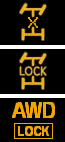
Включена блокировка дифференциала.
Лампочка блокировки межосевого дифференциала

Включена блокировка заднего межосевого дифференциала.
Оси автомобиля и гаечный ключ

Проблемы в системе полного привода.
Надписи 4WD, AWD

Говорит о неисправности в системе полного привода.
Надписи SH-AWD, R.DIFF TEMP

Говорит о перегреве дифференциала или проблемах с системой полного привода.
Надпись 4WAS
![]()
Ошибка по электронно-полноуправляемому шасси 4WAS (4 Wheel Active Steering). Эта система автоматически подруливает задними колесами.
Надпись RAS
![]()
Ошибка по системе подруливания задними колесами RAS (Rear Active Steer).
Значки на панели приборов гибридных автомобилей
Значок батареи или аккумулятор с надписью Main

Сообщает о неисправности основной аккумуляторной батареи гибридного автомобиля или контура высокого напряжения.
Иконка автомобиля с восклицательным знаком
![]()
Проблемы с электроприводом — аналог Check Engine (проверьте двигатель) для гибридных автомобилей.
Иконка батареи с молнией
![]()
Высоковольтная батарея автомобиля разряжена.
Иконка заправочной станции и электрической вилки
![]()
Низкий уровень заряда высоковольтной батареи, необходима зарядка.
Значок черепахи в круге
![]()
Снижение мощности батареи до низких значений.
Лампочка с электрической вилкой

Батарея заряжается (подключена к электрической сети).
Надписи EV или EV Mode

Гибридный автомобиль движется на электротяге (активирован режим EV Mode).
Значок автомобиля с иконками сигнала

Не работает звуковая система предупреждения пешеходов о приближении автомобиля. Такие системы устанавливаются на гибридные и электромобили из-за беззвучной работы силовой установки, из-за чего пешеходы и другие участники дорожного движения могут не слышать приближения автомобиля.
Значок автомобиля с иконками сигнала

Неисправность в силовой цепи электромобиля, может сопровождаться снижением мощности силовой установки. Красный цвет лампочки сигнализирует о критичности ошибки, движение на автомобиле с таким индикатор не рекомендуется.
Значки на приборной панели автомобилей с дизельными двигателями
Красная «колба»
Индикатор неисправности топливного фильтра в автомобиле с дизельным двигателем внутреннего сгорания.
Лампочка со спиралью
![]()
Активирован подогрев свечей накала — эта лампочка загорается после поворота ключа в замке зажигания. Перед запуском двигателя рекомендуется подождать пока эта лампочка потухнет.
Индикатор сажевого фильтра

Требуется замена противосажевого фильтра (Diesel Particulate Filter). Такой фильтр ставится только на дизельные автомобили и предназначен для снижения количества сажи в выхлопных газах.
Иконка низкого уровня реагента очистки выхлопных газов

Требуется долить реагент очистки выхлопных газов AdBlue. Его бачок может располагаться под капотом, рядом с заливной горловиной бензобака, в нише запасного колеса багажника. Пробка горловины бака с жидкостью AdBlue синего цвета. В некоторых странах этот реагент называется AUS 32 (Aqueous Urea Solution 32) или DEF (Diesel Exhaust Fluid).
Надпись Adblue и гаечный ключ
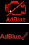
Значки с надписью AdBlue и гаечным ключом или перечёркнутый значок двигателя с надписью AdBlue означают неисправность в системе AdBlue. Необходимо обратиться в сервисный центр.
Значок выхлопа

Обнаружен предельно допустимый уровень эмиссии выхлопных газов. Ошибка говорит о проблемах с дизельным сажевым фильтром (DPF).
Значки наличия воды в выхлопе

Датчики обнаружили наличие воды в топливе. Высокий уровень воды в топливе может стать причиной повреждения форсунок или двигателя. Также эти ошибки могут означать необходимость обслужить систему очистки топлива.
Надпись EDC
![]()
Проблемы с электронной системой впрыска в автомобиле с дизельным двигателем EDC (Electronic Diesel Control). Получает систему с множества датчиков в автомобиле, при неисправности какого-либо из них может загораться такая ошибка.
Ошибка в виде кардиограммы
![]()
Вода в дизельном топливе, неисправность датчика или нарушена работа электронных систем управления двигателем.
Надпись T-BELT
![]()
Ошибка T-BELT означает необходимость замены ремня газораспределительного механизма (ГРМ). Обычно загорается каждые 100 000 километров пробега. Ошибку можно сбросить с помощью диагностического оборудования.
Значки внешних световых приборов
Зеленая лампочка
![]()
Индикатор включенного наружного освещения.
Зеленая лампочка с восклицательным знаком или перечеркнутая лампочка

Одна или несколько ламп наружного освещения перегорели или неисправность в их электрической цепи.
Синий фонарик
![]()
Включен дальний свет.
Синий фонарик

Активирована система управления дальним светом Active High Beam. Датчик в лобовом стекле следит за светом фар встречных автомобилей и светом фонарей попутных машин и при возможности автоматически включает дальний свет.
Лампочка со стрелками вверх-вниз

Неисправен корректор фар, который автоматически регулирует уровень наклона фар в зависимости от загрузки автомобиля. Возможно неисправен датчик наклона кузова.
Надпись AFS OFF или лампочка со стрелками влево-вправо

Ошибка по системе адаптивных фар AFS (Adaptive Front-lighting System). Эта система регулирует положение фар для наилучшего освещения дороги.
Надпись DRL или лампочка с точками

Данные лампочки означают работу системы автоматического включения ближнего света днем DRL (Daytime Running Lamps).
Оранжевая машина и горящие фонари
![]()
Перегорела лампочки или лампочки заднего освещения — стоп-сигналов или фонарей заднего хода.
Зеленые фонари светят в разные стороны
![]()
Включены габаритные огни.
Фонарь светит влево с перечеркнутым светом
![]()
Включены передние противотуманные фары.
Фонарь светит вправо с перечеркнутым светом
![]()
Включены задние противотуманные фары.
Зеленые стрелки в разные стороны
![]()
Мигающая стрелка влево или вправо — включен левый или правый сигнал поворота, мигают обе — включена аварийная световая сигнализация.
Значки дополнительных функций
Человек с ремнем
![]()
Водитель или пассажир не пристегнуты ремнем безопасности.
Открытые двери
![]()
Одна из дверей или багажник не закрыты. Также может означать неисправность одного из концевиков дверей. На некоторых автомобилях концевики зимой замерзают и несмотря на закрытые двери может гореть такая ошибка.
Открытый капот
![]()
Открыт или плохо закрыт капот, проблема с концевиком капота.
Бензоколонка
![]()
Сигнальный индикатор низкого уровня топлива. Также возможна неисправность поплавка в бензобаке.
Надпись GAS
![]()
На автомобилях с газовым оборудованием означает необходимость заправить газовый баллон.
Лобовое стекло с фонтаном
![]()
Низкий уровень омывающей жидкости, нужно долить. Или неисправность датчика уровня омывающей жидкости.
Ошибка по складной крыше кабриолета
![]()
Проблемы с электроприводом складной крыши на автомобилях с кузовом кабриолет.
Если вы не нашли своего значка — пишите нам на почту, мы постараемся Вам помочь. Также если вы считаете, что если какого-то значка не хватает — присылайте его туда же с описанием условий, при которых он отображается — мы обязательно его добавим.
Last Updated on July 15, 2022 by Nick
The new Mini Countryman F60 is a compact SUV from Mini that was introduced in early 2017. The Mini Countryman has been built at VDL Nedcar in Born since 2016. So today, I want to talk about resetting the oil light or service minder on the Mini Countryman F60.
This was the first time that this particular vehicle went to an oil service center after it was out of warranty. I was hoping that I would have a better experience in that regard and they would follow my instructions, but they didn’t do that. That’s okay. I’m gonna teach them how to do that. So we’re gonna do this, and it’s gonna start right now.
Mini Countryman F60 Oil Service Light Reset Procedure
Time needed: 3 minutes.
All right, in this section, I’m going to show you how to reset the oil service light on a 2020 MINI Countryman. It’s real similar to the 2019 model and the regular Mini Coopers. So what I’m going to want to do is:
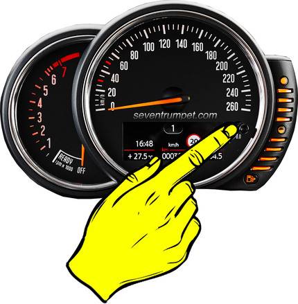
- Get in the car and turn it on without starting the engine
Push the Start button once without touching the brake pedal
- Hold down the TRIP button
So next, what you’ll do is push the TRIP button and hold it down for a few seconds, approximately 35 seconds, until you see the service item

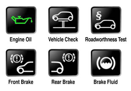
- Find the ENGINE OIL
This mode allows you to reset maintenance items like Engine Oil, Brake Pad, or Brake Fluid. Press the TRIP button briefly until you get to the Engine Oil screen

- Press and hold the TRIP button
When you are on the Engine Oil screen, hold down the TRIP button until RESET? appears on the display
- Release the button and then hold it again to perform the oil reset
Done!
For your information, this operation works for the Mini Cooper Countryman F60, which is equipped with an instrument cluster without enhanced features (2017, 2018, 2019, 2020, 2021, 2022, and 2023 model years). For the R60 model, you can reach it here.
Engine Oil Tips – Viscosity Grades
If you’ve ever looked at a bottle of lubricant, you’ll probably recognize some of these. These are viscosity grades; they tell you what temperature the oil can handle. For instance, how thick is your oil at its normal operating temperature? How cold can it get before your oil stops flowing? How thin is your oil at hot temperatures? Now there are two basic types of grades.
Multi-Grade
First is the multi-grade, which protects a wide temperature range. Or, if you want to sound more official, you could say that multi-grade lubricants maintain the lubricant viscosity at extreme temperature ranges.
In the multi-grade, the 0W-30, for example, there’s winter grade. The W here stands for winter, not weight. Winter grades tell you the thickness of the oil and the absolute lowest temperature the oil will work at. The lower the number in front of the W, the lower the oil’s temperature will remain liquid. This number matters when trying to start your engine on a cold morning.
There are also summer braids which indicate the thickness of the oil at operating temperature (30). This is important on those hot days when you’re sitting in traffic that engines are burning up, and you don’t want it to do the same to your oil.
Mono Grade
When those are used individually, the viscosity is known as the mono grade. Now you might be wondering how the same oil can work just as well when it’s cold as when it’s hot. The answer is these beauty folks in the biz call this a VIII or a Viscosity Index Improvers.
It’s a polymer that gets ground into a powder and adds to the multi-grade oil. The polymer is essential because it expands when heat exposure, making the oil thicker and better protecting those moving engine parts.
Choosing the correct viscosity grade for your lubricant makes a big difference. It means you maintain performance and fuel economy and reduce engine wear regardless of what Mother Nature has installed. If you live in a place with extreme temperatures, look a little closer at the next bottle of lubricant you buy, so your engine will appreciate it.
FAQ – Countryman Oil Change
What kind of oil does a 2017 Mini Countryman take?
SAE 0W-30 BMW Genuine synthetic oil is required in all MINI cars. It’s designed to guarantee that your MINI always operates at its optimum.
How much does it cost for a MINI Cooper oil change?
The cost of an engine oil change for a MINI Cooper typically falls between $150 to $190, with nearly equal amounts of the price going toward materials and labor.
How often does MINI Countryman need an oil change?
Your owner’s handbook will include model-specific advice, but all MINI cars should be serviced every 4,000 to 6,000 miles.
So that is how you reset the oil service light in your Countryman F60. This guide is for somebody who may do their own oil change, although BMW kind of frowns upon that, or if you take it somewhere that is authorized to do it, maybe you got to use it’s no longer under warranty. Thanks for joining me today, and have a good day.
About The Author
jacob
Hi! I’m Jacob. For ten years, I ran a repair business. I have been interested in automobiles since he was a child and spends all of my spare time assisting my father in his garage. I like providing others with useful info.
- Manuals
- Brands
- Mini Manuals
- Automobile
- Countryman Cooper S
- Owner’s manual
-
Contents
-
Table of Contents
-
Bookmarks
Quick Links
Contents
A-Z
OWNER’S MANUAL.
MINI.
Online Edition for Part no. 01 40 2 961 168 — II/15
Related Manuals for Mini Countryman Cooper S
Summary of Contents for Mini Countryman Cooper S
-
Page 1
Contents OWNER’S MANUAL. MINI. Online Edition for Part no. 01 40 2 961 168 — II/15… -
Page 3
The more familiar you are with your vehicle, the better control you will have on the road. We therefore strongly suggest: Read this Owner’s Manual before starting off in your new MINI. Also use the Integrated Owner’s Manual in your vehicle. It con‐… -
Page 4
© 2015 Bayerische Motoren Werke Aktiengesellschaft Munich, Germany Reprinting, including excerpts, only with the written consent of BMW AG, Munich. US English II/15, 03 15 490 Printed on environmentally friendly paper, bleached without chlorine, suitable for recycling. Online Edition for Part no. 01 40 2 961 168 — II/15… -
Page 5
At page 155 under the heading: “Objects in While MINI, at no cost to you, will pay for re- the area around the pedals” and at page pairs required by the limited warranties pro- 217 under the heading: “Carpets and floor… -
Page 6
“Have in lieu thereof should be read as follows: mounting and balancing …” should be dis- MINI recommends that you have the oil regarded and the following text should be changed at your MINI dealer’s service center read in lieu thereof: “BMW recommends that… -
Page 7
Addendum “check control” messages of these comfort functions are no longer displayed. Online Edition for Part no. 01 40 2 961 168 — II/15… -
Page 9: Table Of Contents
Contents MOBILITY The fastest way to find information on a partic‐ ular topic or item is by using the index, refer to Refueling page 230. Fuel Wheels and tires Engine compartment Notes Engine oil Coolant AT A GLANCE Maintenance Cockpit Replacing components Onboard monitor Breakdown assistance…
-
Page 10: Notes
This also applies to safety-related functions and center will be glad to advise you at any time. systems. Information about MINI, e.g., on technology, is The respectively applicable country provisions available on the Internet: www.miniusa.com must be observed when using the respective features and systems.
-
Page 11: Basic Information
MINI. MINI cannot test every product made by other man‐ Manufacturer ufacturers to verify if it can be used on a MINI The manufacturer of this MINI is Bayerische safely and without risk to either the vehicle, its Motoren Werke Aktionengesellschaft, BMW AG.
-
Page 12
Service and warranty damage to the vehicle. Such damage is not covered by the MINI New Vehicle Limited War‐ We recommend that you read this publication ranty. thoroughly. Your vehicle is covered by the fol‐… -
Page 13: Vehicle Identification Number
Notes ▷ Malfunctions and faults in important system ▷ How various systems in your vehicle were components, e.g., lights and brakes. operating. ▷ Responses by the vehicle to special situa‐ ▷ Whether or not the driver and passenger tions such as airbag deployment or engag‐ safety belts were fastened.
-
Page 14: Reporting Safety Defects
National Highway Traffic Safety Administration NHTSA, in addition to notifying MINI of North America, LLC, P.O. Box 1227, Westwood, New Jersey 07675-1227, Telephone 1-800-831-1117.
-
Page 15
Notes Online Edition for Part no. 01 40 2 961 168 — II/15… -
Page 16
WATCH ME. Online Edition for Part no. 01 40 2 961 168 — II/15… -
Page 17: At A Glance
AT A GLANCE CONTROLS DRIVING TIPS MOBILITY REFERENCE Online Edition for Part no. 01 40 2 961 168 — II/15…
-
Page 18: At A Glance Cockpit
AT A GLANCE Cockpit Cockpit Vehicle features and op‐ necessarily available in your car, e. g., due to the selected options or country versions. This tions also applies to safety-related functions and sys‐ tems. The respectively applicable country provi‐ This chapter describes all standard, country- sions must be observed when using the respec‐…
-
Page 19
AT A GLANCE Cockpit Cruise control on/off, inter‐ Cleaning windows 67 rupt 115 Cruise control on/off, inter‐ Rear window wiper 67 rupt 121 Store speed 115, 121 Cleaning rear window 67 Resume speed 117, 122 Steering wheel buttons, right Voice activation 27 speed 117, 121 Telephone Reduce distance 121 Confirm the selection 81 Increase distance 115 Move selection up 81… -
Page 20: All Around The Center Console
AT A GLANCE Cockpit All around the center console Hazard warning system 209 Start/stop the engine and switch the ignition on/off 63 Intelligent Safety 103 DSC Dynamic Stability Con‐ trol 111 Head-up Display 86 Control Display 18 Radio/Multimedia Glove compartment 147 Steptronic transmission selector lever 68 Climate control 132 Manual transmission selector lever 68 PDC Park Distance…
-
Page 21
AT A GLANCE Cockpit All around the roofliner Emergency Request Ambient light 94 Indicator lamp, front-seat passen‐ Glass sunroof 46 airbag 97 Reading lights 94 Interior lights 93 Online Edition for Part no. 01 40 2 961 168 — II/15… -
Page 22: Onboard Monitor
AT A GLANCE Onboard monitor Onboard monitor Vehicle features and op‐ Control elements at a tions glance This chapter describes all standard, country- Control elements specific and optional features offered with the series. It also describes features that are not necessarily available in your car, e.
-
Page 23
AT A GLANCE Onboard monitor Switch off Move in four directions. Press button. «Turn off control display» Buttons on controller Press button Function Controller with navigation system MENU Open the main menu. The buttons can be used to open the menus di‐ RADIO Opens the Radio menu. -
Page 24
AT A GLANCE Onboard monitor Press. The main menu is displayed. All onboard monitor functions can be called up Move in two directions. via the main menu. Selecting menu items Highlighted menu items can be selected. Turn the controller until the desired menu item is highlighted. -
Page 25: Options Menu
AT A GLANCE Onboard monitor Options menu ▷ Move the controller to the right. Opens new display on top of previous The «Options» menu consists of various areas: screen. ▷ Screen settings, e.g., «Split screen». This area remains unchanged. ▷ Control options for the selected main menu, e.g., for «Radio».
-
Page 26
AT A GLANCE Onboard monitor «Touchpad» Function Controls Select the desired function. Interactive map. Swipe into respective direction. ▷ «Speller»: enter letters and numbers. ▷ «Interactive map»: viewing the interac‐ Enlarge/shrink in‐ Drag in or out on the tive map. teractive map. -
Page 27
AT A GLANCE Onboard monitor Telephone symbols Turn the controller until «Time:» is high‐ lighted, and then press the controller. Symbol Meaning Incoming or outgoing call. Missed call. Wireless network reception strength. Symbol flashes: network search. Wireless network is not available. Bluetooth is switched on. -
Page 28: General Information
AT A GLANCE Onboard monitor Split screen Programmable memory buttons General information Additional information can be displayed on the General information right side of the split screen, e.g., information The onboard monitor functions can be stored from the on-board comupter. on the programmable memory buttons and In the divided screen view, the so-called split called up directly, e.g., radio stations, naviga‐…
-
Page 29
AT A GLANCE Onboard monitor «OK» «Continue» «OK» Deleting personal in the Entering letters and vehicle numbers The concept General information Depending on the usage, the vehicle saves per‐ sonal data, such as stored radio stations. These On the Control Display: personal data can be permanently deleted via Turn the controller: select letters or num‐… -
Page 30
AT A GLANCE Onboard monitor Entries are continuously compared with data stored in the vehicle. ▷ Only those letters are offered during input for which data is available. ▷ Target search: names of locations may be entered in languages available through Control Display. -
Page 31: Voice Activation System
AT A GLANCE Voice activation system Voice activation system Vehicle features and op‐ Using voice activation tions Activating the voice activation system This chapter describes all standard, country- specific and optional features offered with the Press button on the steering wheel. series.
-
Page 32: Adjusting The Volume
AT A GLANCE Voice activation system Executing functions using short Setting the voice dialog commands Set system to standard dialog or use a short Execute functions on the main menu via short version. commands. It almost doesn’t matter which The short version of the voice dialog plays back menu item is selected, e.g., ›Vehicle status‹.
-
Page 33
AT A GLANCE Voice activation system ▷ Avoid making other noise in the vehicle while speaking. Online Edition for Part no. 01 40 2 961 168 — II/15… -
Page 34: Integrated Owner’s Manual In The Vehicle
AT A GLANCE Integrated Owner’s Manual in the vehicle Integrated Owner’s Manual in the vehicle Owner’s Manual Vehicle features and op‐ Search for information and descriptions by en‐ tions tering terms selected from the index. This chapter describes all standard, country- Select components specific and optional features offered with the series.
-
Page 35
AT A GLANCE Integrated Owner’s Manual in the vehicle Scroll forward. To alternate permanently between the last dis‐ played function and the Owner’s Manual re‐ peat steps 4 & 5. Opens a new display every time. Context help — Owner’s Manual to the temporarily selected function Programmable memory buttons You may open the relevant information di‐… -
Page 36
HANDLE ME. Online Edition for Part no. 01 40 2 961 168 — II/15… -
Page 37
AT A GLANCE CONTROLS DRIVING TIPS MOBILITY REFERENCE Online Edition for Part no. 01 40 2 961 168 — II/15… -
Page 38: Opening And Closing
CONTROLS Opening and closing Opening and closing Overview Vehicle features and op‐ tions This chapter describes all standard, country- specific and optional features offered with the series. It also describes features that are not necessarily available in your car, e. g., due to the selected options or country versions.
-
Page 39
CONTROLS Opening and closing The battery compartment is accessible. ▷ Interference from radio transmissions through mobile devices in close proximity to remote control. ▷ Interference of radio transmission by charger while charging items such as mo‐ bile devices in the vehicle. A Check Control message is displayed if an at‐… -
Page 40: Profile Management
CONTROLS Opening and closing Profile management If the vehicle is unlocked using a remote con‐ trol, the assigned personal profile will be acti‐ Opening profiles vated. All settings stored in the profile are auto‐ matically applied. Regardless of the remote control in use a differ‐ If several drivers use their own remote control, ent profile may be activated.
-
Page 41
CONTROLS Opening and closing Display profile list during start This can be helpful for securing and retrieving personal settings, before delivering the vehicle The profile list can be displayed during each to a workshop, e.g. Profiles can be taken to an‐ start to select the desired profile. -
Page 42: Courtesy Lights
CONTROLS Opening and closing Panic mode The alarm system, refer to page 43, is dis‐ armed. You can trigger the alarm system if you find yourself in a dangerous situation. Convenient opening Press button on the remote control for Press and hold this button on the re‐ at least 3 seconds.
-
Page 43
CONTROLS Opening and closing Without remote control ▷ Shielding of the remote control due to metal objects. ▷ Interference of the radio connection from From the outside mobile phones or other electronic devices Locking from the outside in direct proximity. Do not lock the vehicle from the outside Do not transport the remote control together with people inside the car, as the vehicle can‐… -
Page 44: Locking And Unlocking
CONTROLS Opening and closing From the inside Do not place the remote control in the cargo area Locking and unlocking Take the remote control with you and do not leave it in the cargo area; otherwise, the re‐ mote control is locked inside the vehicle when the tailgate is closed.◀…
-
Page 45
CONTROLS Opening and closing Closing Unlocking Recessed grips on the inside trim of the tailgate On the driver’s or front passenger’s door han‐ can be used to conveniently pull down the tail‐ dle, press the button, arrow. gate. This corresponds to pressing the remote control button: Comfort Access Locking… -
Page 46
CONTROLS Opening and closing ▷ Interference of the radio connection from mobile phones or other electronic devices in direct proximity. Do not transport the remote control together with metal objects or electronic devices. In the case of a malfunction, unlock and lock the vehicle using the buttons of the remote control or using the integrated key, refer to page 39. -
Page 47: Alarm System
CONTROLS Opening and closing Tailgate Alarm system Depending on optional features and country version, this setting is not offered in some The concept cases. When the vehicle is locked, the vehicle alarm system responds to: «Settings» ▷ Opening a door, the hood or the tailgate. «Doors/key»…
-
Page 48: Interior Motion Sensor
CONTROLS Opening and closing Interior motion sensor To reel off the alarm: press any button. The windows and glass sunroof must be closed Indicator lamp on the interior rearview for the system to function properly. mirror Avoiding unintentional alarms The tilt alarm sensor and interior motion sensor can be switched off together, such as in the fol‐…
-
Page 49: Power Windows
CONTROLS Opening and closing Closing Power windows Keep the closing path clear Note Monitor closing and make sure that the closing path of the window is clear; otherwise, Take the remote control with you injuries may result.◀ Take the remote control with you when leaving the vehicle so that children, e.g., cannot Pull switch up.
-
Page 50
CONTROLS Opening and closing At a glance Pull the switch past the resistance point again within approx. 4 seconds and hold it there. The window closes without jam protection. On 5-door models: safety switch The safety switch in the driver’s door can be used to prevent children, e.g., from opening and closing the rear windows using the switches in the rear. -
Page 51
After a power failure, it can happen that the ance point and release it twice. glass sunroof can only be raised. The system must be initialized in this case. MINI recom‐ The glass sunroof is closed. mends having this work performed by your Pressing the reel again stops the motion. -
Page 52: Adjusting
CONTROLS Adjusting Adjusting Vehicle features and op‐ would eliminate the protection normally pro‐ vided by the belt.◀ tions Keep the movement area unobstructed This chapter describes all standard, country- When changing the seat position, keep specific and optional features offered with the the seat’s area of movement unobstructed;…
-
Page 53: Lumbar Support
CONTROLS Adjusting After releasing the lever, move the seat forward or back slightly making sure it engages prop‐ erly. Height Turn the wheel in order to increase or decrease the curvature. Thigh support Pull the lever up or press it down as often as needed to reach the desired height.
-
Page 54: Safety Belts
CONTROLS Adjusting Fold down seat back If the journey is continued within approx. 15 minutes, the seat heating is activated automat‐ Pull lever up to the stop. ically with the temperature selected last. When Green mode, refer to page 162, is acti‐ vated, the heater output is reduced.
-
Page 55: Front Head Restraints
CONTROLS Adjusting Hints Unbuckling the belt Hold the belt firmly. One person per safety belt Press the red button in the belt buckle. Never allow more than one person to wear a single safety belt. Never allow infants or Guide the belt back into its roll-up mecha‐ small children to ride on a passenger’s lap.◀…
-
Page 56: Rear Head Restraints
CONTROLS Adjusting Height Before transporting passengers Adjust the head restraint so that its center is Reinstall the head restraint before trans‐ approximately at ear level. porting anyone in the seat; otherwise, the pro‐ tective function of the head restraint is unavail‐ Distance able.◀…
-
Page 57: Exterior Mirrors
CONTROLS Adjusting Mirrors in the rear; otherwise, there is increased risk of injury in the event of an accident.◀ Exterior mirrors General information The mirror on the passenger side is more curved than the driver’s side mirror. Depending on the vehicle equipment, the mir‐ ror setting is stored for the profile currently in use.
-
Page 58: Automatic Dimming Feature
CONTROLS Adjusting Adjusting electrically Fold in the mirror in a car wash Before washing the car in an automatic The setting corresponds to the direction car wash, fold in the exterior mirrors by hand or in which the button is pressed. with the button;…
-
Page 59: Steering Wheel
CONTROLS Adjusting Turn knob Steering wheel Note Do not adjust while driving Do not adjust the steering wheel while driving; otherwise, an unexpected movement could result in an accident.◀ Adjusting Turn the knob to reduce the blinding effect by the interior mirror. Interior rearview mirror, automatic dimming feature The concept…
-
Page 60: Transporting Children Safely
CONTROLS Transporting children safely Transporting children safely Vehicle features and op‐ necessarily available in your car, e. g., due to the selected options or country versions. This tions also applies to safety-related functions and sys‐ tems. The respectively applicable country provi‐ This chapter describes all standard, country- sions must be observed when using the respec‐…
-
Page 61: Deactivating Airbags
CONTROLS Transporting children safely there is an increased risk of injury because of move the passenger seat carefully forward until unexpected movement of the seat backrest.◀ the best possible belt guide position is reached. In order to faciliate the installation of a back- Child seat security facing child restraint system in the rear: move the front passenger’s seat as far up as…
-
Page 62
CONTROLS Transporting children safely Mounting points and CRS weight of 65 lb when the child is re‐ strained by the internal harnesses. The respective symbol shows the an‐ Properly engage the lower LATCH an‐ chor for the upper retaining strap. Seats chors with an upper Top Tether are marked with this symbol. -
Page 63
CONTROLS Transporting children safely No persons on the back seat when there This locks various functions so that they cannot is a child restraint system with an upper be operated from the rear: safety switch, refer retaining strap on the front passenger seat. to page 46. -
Page 64: Driving
CONTROLS Driving Driving Vehicle features and op‐ To save battery power when the engine is off, switch off the ignition and any unnecessary tions electronic systems/power consumers. This chapter describes all standard, country- Ignition off specific and optional features offered with the Manual transmission: press the Start/Stop but‐…
-
Page 65: Manual Transmission
CONTROLS Driving ▷ After approx. 8 minutes. posing a risk of overheating and damage to the catalytic converter.◀ ▷ When the vehicle is locked using the central locking system. Do not wait for the engine to warm-up while ▷ Shortly before the battery is discharged the vehicle remains stationary.
-
Page 66: Automatic Operation
CONTROLS Driving hicle, e.g., by turning the steering wheel in the the Auto Start/Stop function is active, it is avail‐ direction of the curb.◀ able when the vehicle is traveling faster than about 3 mph, approx. 5 km/h. Before driving into a car wash Engine stop So that the vehicle can roll into a car wash ob‐…
-
Page 67: Functional Limitations
CONTROLS Driving Functional limitations Some indicator lights light up for a varied length of time. The engine is not switched off automatically in the following situations: The engine can only be started via the Start/ Stop button. ▷ External temperature too low. ▷…
-
Page 68: Parking Brake
CONTROLS Driving ▷ LED comes on: Auto Start/Stop function is The indicator lamp lights up red. The deactivated. parking brake is set. The engine is started during an automatic Lower lamp: indicator lamp in Canadian engine stop. models The engine can only be stopped or started via the Start/Stop button.
-
Page 69: Headlight Flasher
CONTROLS Driving High beams, headlight flasher Turn signal, high beams, headlight flasher Turn signal Using turn signals ▷ High beams, arrow 1. ▷ Headlight flasher, arrow 2. Washer/wiper system Press the lever beyond the resistance point. Switching the wipers on/off and brief To switch off manually, press the lever to the wipe resistance point.
-
Page 70
CONTROLS Driving Switching on Interval mode or rain sensor The concept Without the rain sensor, the frequency of the wiper operation is preset. The rain sensor automatically controls the time between wipes depending on the intensity of the rainfall. The sensor is located on the wind‐ shield, directly behind the interior rearview mir‐… -
Page 71: Washer Fluid
CONTROLS Driving Washing the windshield Cleaning rear window In interval mode: turn the switch further, ar‐ row 2. The switch automatically returns to its interval position when released. In idle position: turn switch downward, arrow 3. The switch automatically returns to its idle posi‐ tion when released.
-
Page 72
CONTROLS Driving Follow the notes and instructions on the con‐ Recommended minimum fill quantity: 0.2 US tainer. gal/1 liter. United States: The washer fluid mixture ratio is regulated by the U.S. EPA and many individual Manual transmission states; do not exceed the allowable washer fluid dilution ratios limits that apply. -
Page 73
CONTROLS Driving Kickdown Sport program and manual mode M/S Kickdown is used to achieve maximum driving Activating the sport program performance. Step on the accelerator pedal be‐ yond the resistance point at the full throttle po‐ sition. Engaging a selector lever position Press on the brake pedal until you start driving To prevent the vehicle from creeping after you… -
Page 74
CONTROLS Driving The selected gear is briefly displayed in the in‐ ▷ Shift down: briefly pull left shift paddle. strument cluster, followed by the currently se‐ ▷ With the respective transmission version, lected gear. the lowest possible gear can be selected by pulling and holding the left shift paddle. -
Page 75: The Concept
CONTROLS Driving Before unlocking the transmission lock man‐ An experienced driver may be able to achieve ually, engage the parking brake forcefully to better acceleration values in DSC OFF mode, re‐ prevent the vehicle from rolling away. fer to page 111. Loosen the sleeve of the selector lever.
-
Page 76: Displays
CONTROLS Displays Displays Vehicle features and op‐ necessarily available in your car, e. g., due to the selected options or country versions. This tions also applies to safety-related functions and sys‐ tems. The respectively applicable country provi‐ This chapter describes all standard, country- sions must be observed when using the respec‐…
-
Page 77: Check Control
CONTROLS Displays Electronic displays Driver assistance systems On-board computer 81 Messages, e.g. Check Control Selector lever position display 68 Time 77 Gear shift indicator 79 External temperature 77 Driving Dynamics Control 113 Selection lists 81 Status Total miles/trip odometer 77 Indicator/warning lights Check Control General information The concept The indicator and warning lights can light up in The Check Control system monitors functions in a variety of combinations and colors.
-
Page 78
CONTROLS Displays Orange lights be activated if objects are placed on the front passenger seat. Active Cruise Control Make sure that the safety belts are positioned correctly. The number bars shows the selected distance from the vehicle driving ahead. Airbag system For more information, see Camera- based cruise control, ACC, refer to page 115. -
Page 79
CONTROLS Displays DSC Dynamic Stability Control is deactivated Steering system or DTC Dynamic Traction Control is activated Steering system in some cases defec‐ Dynamic Stability Control DSC is tive. switched off or Dynamic Traction Con‐ Have the steering system checked by trol DTC is switched on. -
Page 80
CONTROLS Displays Symbols High-beam Assistant Within the supplementary text, the following High-beam Assistant is switched on. functions can be selected independent of the High beams are activated and off auto‐ check control message. matically as a function of the traffic sit‐ ▷… -
Page 81: Resetting The Trip Odometer
CONTROLS Displays Displaying stored Check Control Resetting the trip odometer messages Press the knob. On the Control Display: ▷ The odometer is displayed when the ignition is switched «Vehicle info» off. «Vehicle status» ▷ When the ignition is switched «Check Control» on, the trip odometer is re‐…
-
Page 82: Service Requirements
CONTROLS Displays Range Service requirements Display The concept After the ignition is turned on the instrument With a low remaining range: cluster briefly displays available driving distance ▷ A Check Control message is or time to the next scheduled maintenance. displayed briefly.
-
Page 83: Gear Shift Indicator
CONTROLS Displays Steptronic transmission: Displaying On the Control Display: «Vehicle info» Example Description «Vehicle status» Fuel efficient gear is set. «Service required» «§ Vehicle inspection» Shift into fuel efficient gear. «Date:» Adjust the settings. Confirm. The entered date is stored. Speed limit detection Gear shift indicator The concept…
-
Page 84
CONTROLS Displays The system assists the driver and does not re‐ With navigation system: speed place the human eye.◀ limit detection is not available. At a glance Camera Without navigation system: speed limit detection switched on but no speed limit or cancel‐ lation is detected. -
Page 85
CONTROLS Displays Selection lists in the in‐ On-board computer strument cluster Calling up information on the info display The concept With the buttons on the steering wheel and the display in the instrument cluster the following can be displayed or operated: ▷… -
Page 86: Average Fuel Consumption
CONTROLS Displays ▷ Speed. temperature has been attained, the indicator is in the center position. If the engine oil or coolant, thus the engine, be‐ Adjusting the info display come too hot, a Check Control message is dis‐ You can select what information from the com‐ played.
-
Page 87
CONTROLS Displays Display on the Control Display Vehicle state Display the computer or trip computer on the The following vehicle and surrounding area Control Display. data are automatically checked and evaluated in succession: On the Control Display: ▷ Range. «Vehicle info» ▷… -
Page 88
CONTROLS Displays Turn the controller until the desired limit is Turn the controller until the desired hours displayed. are displayed. Press the controller. Press the controller. The speed limit is stored. Turn the controller until the desired mi‐ nutes are displayed. Activating/deactivating the limit Press the controller. -
Page 89: Instrument Cluster
CONTROLS Displays Language Depending on the light conditions, the bright‐ ness settings may not be clearly visible. Setting the language To set the language on the Control Display: LED ring on the central «Settings» instrument cluster «Language/Units» «Language:» The concept Select the desired language.
-
Page 90: Head-Up Display
CONTROLS Displays Hints ▷ Arrow 3: warning field. Do not move the moving parts manually Switching on/off LED ring Do not move the moving parts manually, «Settings» and keep the area of movement of these parts «Center Instrument» clear; otherwise, the system is damaged.◀…
-
Page 91
CONTROLS Displays On the Control Display: «Settings» «Head-Up Display» «Brightness» Turn the controller. When the low beams are activated, the bright‐ ness of the Head-up Display can be additionally influenced using the instrument lighting, refer Press button. to page 93. Settings are stored for the profile currently in use. -
Page 92
CONTROLS Displays Overview, buttons tal times can be measured using the stop watch. The display elements of the Chrono package mainly support a sporty driving style, e,g, on racetracks. Overview ▷ MODE button, arrow 1. ▷ START/STOP button, arrow 2. ▷… -
Page 93
CONTROLS Displays watch, e.g., LAP 1 with the measured time. The stop watch continues running in the background. If needed, press button, arrow 3, again to measure a further lap time. Calling up lap times Press button, arrow 1, repeatedly until LAP 1 is shown on the display. -
Page 94: Lights
CONTROLS Lights Lights Vehicle features and op‐ Parking lights, corner‐ tions ing lights and roadside parking lights This chapter describes all standard, country- specific and optional features offered with the General information series. It also describes features that are not necessarily available in your car, e.
-
Page 95: Daytime Running Lights
CONTROLS Lights Switching on Automatic headlight With the ignition switched off, press the lever control either up or down past the resistance point for approx. 2 seconds. Position of switch : the low beams are acti‐ vated and off automatically, e.g., in tunnels, in Switch off twilight or if there is precipitation.
-
Page 96
CONTROLS Lights Activating Cornering lamp Position of switch : going around corners, the cornering lamp also lights the interior area of the curve. Below a speed of approx. 25 mph/40 km/h when the flasher is switched on and the steering angle is detected, there is automatic activation. -
Page 97: Instrument Lighting
CONTROLS Lights Rear fog lights The High-beam Assistant can be switched off when manually adjusting the light. To reacti‐ The low beams or front fog lights must be vate the High-beam Assistant, press the button switched on. on the turn signal lever. Press button.
-
Page 98: Reading Lights
CONTROLS Lights Overview Changing color Push the switch forward or back: manual color change. Push and hold the switch forward or back: automatic color change. Push the switch again to end color changes. Setting the brightness The brightness of the ambient light can be ad‐ Interior lights justed via the thumbwheel for the instrument Reading lamp…
-
Page 99: Safety
CONTROLS Safety Safety Vehicle features and op‐ necessarily available in your car, e. g., due to the selected options or country versions. This tions also applies to safety-related functions and sys‐ tems. The respectively applicable country provi‐ This chapter describes all standard, country- sions must be observed when using the respec‐…
-
Page 100
CONTROLS Safety Knee airbag ▷ Do not apply adhesive materials to the air‐ bag cover panels, do not cover them or The knee airbag supports the legs in a frontal modify them in any way. impact. ▷ Never modify either the individual compo‐ Protective action nents or the wiring in the airbag system. -
Page 101
CONTROLS Safety In case of a malfunction have airbag sys‐ ▷ Do not attach covers, cushions, ball mats or tem checked immediately. other items to the front passenger seat un‐ less they are specifically recommended by In case of a malfunction have airbag system your vehicle’s manufacturer. -
Page 102: Tire Pressure Monitor
CONTROLS Safety Tire Pressure Monitor After installing a child seat, make sure that the indicator lamp for the front-seat passenger air‐ bags lights up. This indicates that the child seat has been detected and the front-seat passen‐ The concept ger airbags are not activated. The system monitors tire inflation pressure in Strength of the driver’s and front-seat the four mounted tires.
-
Page 103
CONTROLS Safety Status control display After driving faster than 19 mph/30 km/h for a short period, the set tire inflation pressures are Tire and system status are indicated by the accepted as reference values. The resetting color of the tires and a text message on the process is completed automatically while driv‐… -
Page 104
CONTROLS Safety Do this by checking the air pressure in all A vehicle with a damaged tire reacts differently, four tires. e.g., it has reduced lane stability during brak‐ ing, a longer braking distance and different The tire pressure gauge of the Mobility Sys‐ self-steering properties. -
Page 105
CONTROLS Safety ▷ Carry out a reset of the system after a tire pressure label, you should determine the change. proper tire inflation pressure for those tires.) As an added safety feature, your vehicle has been System limits equipped with a tire pressure monitoring sys‐ tem (TPMS) that illuminates a low tire pressure The system does not function properly if a reset telltale when one or more of your tires is signifi‐… -
Page 106
CONTROLS Safety FTM Flat Tire Monitor «Perform reset» Start the engine — do not drive off. The concept Start the initialization with «Perform reset». The system does not measure the actual infla‐ Drive away. tion pressure in the tires. The initialization is completed while driving, It detects a tire inflation pressure loss by com‐… -
Page 107
CONTROLS Safety ▷ When the system has not been initialized. Possible driving distance with complete loss of tire inflation pressure: ▷ When driving on a snowy or slippery road surface. The possible driving distance after a loss of tire inflation pressure depends on cargo load, driv‐ ▷… -
Page 108
CONTROLS Safety At a glance The intelligent safety systems can hel prevent an imminent collision. Button in the vehicle ▷ Front-end collision warning with City Brak‐ ing function, refer to page 105. ▷ Pedestrian warning with city braking func‐ tion, refer to page Hints Personal responsibility The system does not serve as a substitute… -
Page 109
CONTROLS Safety Hints Front-end collision warning with City Brak‐ Personal responsibility The system does not serve as a substitute ing function for the driver’s personal judgment of the traffic situation. The concept Be aware of the traffic situation and the vehi‐ The ystem can help prevent accidents. -
Page 110
CONTROLS Safety Camera Setting the warning time The warning time can be set via the onboard monitor. «Settings» «Frontal Coll. Warning» Activate the desired warning time on the Control Display. The selected warning time is stored for the pro‐ file currently in use. The camera is found near the interior rearview Warning with braking function mirror. -
Page 111
CONTROLS Safety Acute warnings can also be triggered without ▷ In heavy fog, rain, sprayed water or snow‐ previous prewarning. fall. ▷ In tight curves. Braking intervention ▷ If the camera viewing field or the front The warning prompts the driver himself/herself windshield are dirty or covered. -
Page 112
CONTROLS Safety Under those circumstances it reacts to people Be alert who are within the detection range of the sys‐ Due to system limitations, warnings may tem. be not issued at all, or may be issued late or im‐ properly. Therefore, always be alert and ready Detection range to intervene;… -
Page 113
CONTROLS Safety Switching on/off is sufficiently quick and sufficiently hard step‐ ping on the brake pedal. The system can assist Switching on automatically with some braking intervention if there is risk of a collision. At low speeds vehicles may thus The system is automatically active after every come to a complete stop. -
Page 114: Brake Force Display
CONTROLS Safety ▷ If the driving stability control systems are deactivated, e.g. DSC OFF. ▷ Up to 10 seconds after the start of the en‐ gine, via the Start/Stop knob. ▷ During calibration of the camera immedi‐ ately after vehicle shipment. ▷…
-
Page 115: Driving Stability Control Systems
CONTROLS Driving stability control systems Driving stability control systems Vehicle features and op‐ DSC Dynamic Stability tions Control This chapter describes all standard, country- The concept specific and optional features offered with the DSC prevents traction loss in the power wheels series.
-
Page 116
CONTROLS Driving stability control systems The DSC system is switched off. ▷ When freeing vehicle from deep snow or driving off from loose grounds. ▷ When driving with snow chains. Activating DSC Press button. Deactivating/activating DTC Dynamic DSC OFF and the DSC OFF indicator Traction Control lamp go out. -
Page 117
CONTROLS Driving stability control systems MID/GREEN Configuring GREEN Balanced tuning of the shock absorbers for Via the Driving Dynamics Control more comfort. Activate GREEN. SPORT «Configure GREEN» Consistently sporty tuning of the shock absorb‐ Configure the program. ers for greater driving agility. This configuration is retrieved when GREEN is activated. -
Page 118: Drive-Off Assistant
CONTROLS Driving stability control systems Drive-off assistant Configure the program. SPORT can also be configured before it is acti‐ This system supports driving off on inclines. The vated: parking brake is not required. «Settings» Hold the vehicle in place with the foot «Driving mode»…
-
Page 119: Driving Comfort
CONTROLS Driving comfort Driving comfort General information Vehicle features and op‐ The system is functional at speeds beginning at tions approx. 20 mph/30 km/h. This chapter describes all standard, country- Depending on the set drive mode, refer to specific and optional features offered with the page 113, the features of the cruise control can series.
-
Page 120
CONTROLS Driving comfort At a glance Switching on/off and interrupting cruise control Buttons on the steering wheel Switching on Press button Function Press button on the steering wheel. Cruise control on/off, interrupt, re‐ fer to page Display in the instrument cluster lights Store/maintain speed, refer to page Display in the instrument cluster lights… -
Page 121: While Driving
CONTROLS Driving comfort ▷ The detection range of the camera is im‐ If active, the displayed speed is stored and the paired, e.g., by soiling, heavy precipitation vehicle reaches the stored speed when the or glare effects from the sun. road is clear.
-
Page 122
CONTROLS Driving comfort Brief status display lected distance is briefly displayed in the info display. Selected desired speed. In the following cases, the stored speed value is deleted and cannot be called up again: If — appears briefly on the display for Check ▷… -
Page 123
CONTROLS Driving comfort pressing on the brake pedal or accelerator Comply with the legal speed limit and safety pedal. distance in every situation when using the sys‐ tem. The vehicle symbol flashes red and an acoustic signal sounds: Detection range You are requested to intervene by brak‐… -
Page 124: Swerving Vehicles
CONTROLS Driving comfort Swerving vehicles In tight curves the system offers only restricted detection where a vehicle ahead of you might be detected late or not at all. A vehicle driving in front of you is not detected until it is completely within the same lane as your vehicle.
-
Page 125: Cruise Control
CONTROLS Driving comfort Cruise control Press button Function Increasing, maintaining or storing The concept the speed The system is functional at speeds beginning at Reducing, maintaining or storing approx. 20 mph/30 km/h. the speed It maintains the speed that was set using the control elements on the steering wheel.
-
Page 126: Indicator Lamp
CONTROLS Driving comfort ▷ Selector lever position N is set. The maximum speed that can be set de‐ pends on the vehicle. ▷ DTC Dynamic Traction Control is activated or DSC is deactivated. ▷ button: pressing it to the resist‐ ance point and holding it there accelerates ▷…
-
Page 127
CONTROLS Driving comfort At a glance PDC Park Distance Con‐ trol Button in the vehicle The concept PDC supports you when parking. Slowly ap‐ proaching an object behind or, with the appro‐ priate equipment, also in front of your vehicle is signaled by: ▷… -
Page 128
CONTROLS Driving comfort Switching on/off manually A display appears as soon as Park Distance Control (PDC) is activated. Press button. The range of the sensors is represented in col‐ ors: red, green and yellow. ▷ On: the LED lights up. When the image of the rearview camera is dis‐… -
Page 129: Rearview Camera
CONTROLS Driving comfort False warnings Rearview camera PDC may issue a warning under the following conditions even though there is no obstacle The concept within the detection range: The rearview camera provides assistance in ▷ In heavy rain. parking and maneuvering backwards. The area behind the vehicle is shown on the Control Dis‐…
-
Page 130
CONTROLS Driving comfort Clean the camera lens, refer to page 217. Lanes and turning radius are indicated. ▷ Obstacle marking Switching on/off «Obstacle marking» Spatially-shaped markings are displayed. Switching on automatically With the engine running, engage lever in posi‐ Pathway lines tion P R. -
Page 131: Display Settings
CONTROLS Driving comfort Obstacle marking Display settings Brightness With the rearview camera switched on: Select the symbol. Turn the controller until the desired setting is reached and press the controller. Contrast With the rearview camera switched on: ▷ Obstacle markings can be faded into the image of the rearview camera.
-
Page 132
CONTROLS Driving comfort This system assists the driver in parking parallel Curbs to the road. The parking assistant may steer the vehi‐ Ultrasound sensors measure parking spaces on cle over or onto curb if need be. both sides of the vehicle. Therefore, always be alert and ready to inter‐… -
Page 133
CONTROLS Driving comfort At a glance Parking assistant is activated automatically. Button in the vehicle Switching on with reverse gear Shift into reverse. The current status of the parking space search is indicated on the Control Display. To activate: «Parking Assistant» Switch off The system can be deactivated as follows: ▷… -
Page 134
CONTROLS Driving comfort Interrupting automatically is active, suitable parking spaces are high‐ lighted. The system is interrupted automatically in the ▷ The parking procedure is ac‐ following situations: tive. Steering control has ▷ If the driver grasps the steering wheel or if been taken over by system. -
Page 135
CONTROLS Driving comfort Limits of ultrasonic measurement Ultrasonic measuring might not function under the following circumstances: ▷ For small children and animals. ▷ For persons with certain clothing, e.g. coats. ▷ With external interference of the ultra‐ sound, e.g. from passing vehicles or loud machines. -
Page 136: Climate Control
CONTROLS Climate control Climate control Vehicle features and op‐ necessarily available in your car, e. g., due to the selected options or country versions. This tions also applies to safety-related functions and sys‐ tems. The respectively applicable country provi‐ This chapter describes all standard, country- sions must be observed when using the respec‐…
-
Page 137
CONTROLS Climate control Note Temperature Sufficient ventilation Turn the ring to set the desired temperature. When remaining in the vehicle for an ex‐ tended period of time, ensure sufficient exter‐ nal ventilation. Do not continuously use recircu‐ lated-air mode; otherwise the air quality in the interior continuously deteriorates and window Cooling function condensation… -
Page 138: Rear Window Defroster
CONTROLS Climate control Switching the system on/off Sufficient ventilation When remaining in the vehicle for an ex‐ Switch off tended period of time, ensure sufficient exter‐ nal ventilation. Do not continuously use recircu‐ Turn wheel for air quantity to the lated-air mode;…
-
Page 139: Automatic Climate Control
CONTROLS Climate control Automatic climate control Temperature, left 10 Cooling function Display 11 Automatic recirculated-air control/recircu‐ lated-air mode Air flow, AUTO intensity 12 Rear window defroster AUTO program 13 Windshield defroster Air distribution, manual 14 Defrosts windows and removes condensa‐ Display tion Temperature, right…
-
Page 140: Maximum Cooling
CONTROLS Climate control by increasing the cooling or heating output, Turn the ring to set the desired and then keeps it constant. intensity. Do not rapidly switch between different tem‐ perature settings. The automatic climate con‐ trol will not have sufficient time to adjust the The selected intensity is displayed on the auto‐…
-
Page 141
CONTROLS Climate control Depending on the weather, the windshield may The rear window defroster switches off auto‐ fog up briefly when the engine is started. matically after a certain period of time. The cooling function is switched on automati‐ When Green mode, refer to page 162, is acti‐ cally with the AUTO program. -
Page 142
CONTROLS Climate control Switching on/off directly Ventilation On the Control Display: «Settings» «Climate» «Activate comf. ventilation» The symbol on the automatic climate con‐ trol flashes if the system is switched on. Preselecting the reel-on time On the Control Display: ▷ Turn knob for continuous opening and clos‐… -
Page 143: Interior Equipment
CONTROLS Interior equipment Interior equipment Compatibility Vehicle features and op‐ tions If this symbol is printed on the packag‐ ing or in the instructions of the system This chapter describes all standard, country- to be controlled, the system is generally specific and optional features offered with the compatible with the Universal Integrated Re‐…
-
Page 144
CONTROLS Interior equipment Hold the hand-held transmitter for the sys‐ and continuous illumination of the LED will re‐ tem to be controlled approx. 1 to 3 in/2.5 peat for approximately 20 seconds. to 8 cm away from the buttons of the inte‐ For systems with an alternating-code system, rior rearview mirror. -
Page 145: Digital Compass
CONTROLS Interior equipment Digital compass button on the interior rearview mirror has been programmed. The system can then be controlled by the button on the interior Overview rearview mirror. If the LED does not flash faster after at least 60 seconds, change the distance and re‐ peat the step.
-
Page 146
CONTROLS Interior equipment World map with magnetic zones Procedure Procedure Press and hold the control button for ap‐ Make sure that there are no large metallic prox. 3 to 4 seconds. The number of the set objects or overhead power lines near the compass zone appears in the mirror. -
Page 147: Sun Visor
CONTROLS Interior equipment Settings are stored automatically after approxi‐ Switch off the ignition and take the remote mately 10 seconds. control with you when leaving the vehicle so that children cannot use the lighter and burn themselves.◀ Sun visor Replace the cover after use Reinsert the lighter or socket cover after Glare shield use, otherwise objects may get into the lighter…
-
Page 148: Cargo Area
CONTROLS Interior equipment nition switched on. The total load of all sockets ▷ Do not connect devices such as fans or must not exceed 140 watts at 12 volts. lights to the USB interface. Do not damage the socket by using unsuitable ▷…
-
Page 149
CONTROLS Interior equipment Pull the cargo cover out of the brackets on stability of the child seat can be affected, and the left and right. there is an increased risk of injury because of unexpected movement of the seat backrest.◀ Using the middle safety belt If the middle safety belt in the rear is used, the larger side of the backrest must be… -
Page 150
CONTROLS Interior equipment Fold up the backrest and press it into the latch. Make sure that the safety belt is not pinched. Adjusting the backrest tilt Do not install any child restraint systems When the backrests are set at steeper po‐ sition, do not install any child restraint systems on the backrest;… -
Page 151: Storage Compartments
CONTROLS Storage compartments Storage compartments Vehicle features and op‐ ▷ Storage compartment in the center arm‐ rest. tions ▷ Compartments in the doors. This chapter describes all standard, country- ▷ Pockets on the backrests of the front seats. specific and optional features offered with the series.
-
Page 152: Storage Compartment
CONTROLS Storage compartments Opening Storage compartment above the glove com‐ partment Note Immediately close the storage compart‐ ment Close the storage compartment immediately after use while driving; otherwise, injury may Press button, arrow 1, and open center arm occur during accidents.◀…
-
Page 153: Clothes Hooks
CONTROLS Storage compartments Front No heavy objects Do not hang heavy objects from the hooks; otherwise, they may present a danger to passengers during braking and evasive ma‐ neuvers.◀ The clothes hooks are located above the side windows in the rear. Storage space under In the center console.
-
Page 154
CONTROLS Storage compartments Removing the cargo floor panel Folded up position The variable cargo floor panel may not be used as a partition net to separate the trunk and the vehicle interior. ▷ Only use the variable cargo floor in the folded-up position when the backrests are folded up and locked. -
Page 155
CONTROLS Storage compartments ▷ On 5-door models: Maximum load in this position: 441 lbs/200 kg. ▷ Space for objects remains between the fixed and variable trunk floor. Online Edition for Part no. 01 40 2 961 168 — II/15… -
Page 156
DRIVE ME. Online Edition for Part no. 01 40 2 961 168 — II/15… -
Page 157: Driving Tips
AT A GLANCE CONTROLS DRIVING TIPS MOBILITY REFERENCE Online Edition for Part no. 01 40 2 961 168 — II/15…
-
Page 158: Things To Remember When Driving
DRIVING TIPS Things to remember when driving Things to remember when driving Tires Vehicle features and op‐ Tire traction is not optimal due to manufactur‐ tions ing circumstances when tires are brand-new; they achieve their full traction potential after a This chapter describes all standard, country- break-in time.
-
Page 159: Driving Through Water
DRIVING TIPS Things to remember when driving ▷ Close all windows and the glass sunroof. loss of contact between the tires and the road surface, ultimately undermining your ability to ▷ Greatly increase the air flow from the vents. steer and brake the vehicle. ▷…
-
Page 160: Driving In Wet Conditions
DRIVING TIPS Things to remember when driving Driving in wet conditions Corrosion buildup on the brake discs will cause a pulsating effect on the brakes in their re‐ When roads are wet or in heavy rain, press sponse — generally that cannot be corrected. brake pedal ever so gently every few miles.
-
Page 161: Loading
DRIVING TIPS Loading Loading Vehicle features and op‐ Determining the load tions limit This chapter describes all standard, country- Locate the following statement on your ve‐ specific and optional features offered with the hicle’s placard: series. It also describes features that are not ▷…
-
Page 162: Securing Cargo
DRIVING TIPS Loading Load Securing cargo On 3-door models Lashing eyes in the cargo area Without storage compartment package: to se‐ On 5-door models cure the cargo there are two lashing eyes, ar‐ row 1, in the cargo area. With storage compartment package: to secure the cargo there are six lashing eyes, arrows 1 and 2, in the cargo area.
-
Page 163: Rear Luggage Rack
DRIVING TIPS Loading Securing Securing Follow the installation instructions of the roof COOPER/COOPER D/ONE/ONE D rack. Loading Be sure that adequate clearance is maintained for tilting and opening the glass sunroof. Because roof racks raise the vehicle’s center of gravity when loaded, they have a major effect on vehicle handling and steering response.
-
Page 164
DRIVING TIPS Loading ▷ Backup lamp: 42 watts in total. Online Edition for Part no. 01 40 2 961 168 — II/15… -
Page 165: Saving Fuel
DRIVING TIPS Saving fuel Saving fuel Vehicle features and op‐ Close the windows and tions glass sunroof This chapter describes all standard, country- Driving with the glass sunroof and windows specific and optional features offered with the open results in increased air resistance and series.
-
Page 166: Online Edition For Part No. 01 40 2 961 168 — Ii/15
Have the maintenance carried out by your erator and let the vehicle roll. service center. The flow of fuel is interrupted while coasting. Please also note the MINI Maintenance System, refer to page 195. Switch off the engine during longer stops GREEN mode Switch off the engine during longer stops, e.g.,…
-
Page 167: Online Edition For Part No. 01 40 2 961 168 — Ii/15
DRIVING TIPS Saving fuel The Coasting driving condition is enabled under «GREEN Mode» certain conditions. Under certain conditions the engine is auto‐ «Settings» matically decoupled from the transmission in «Driving mode» selector lever position D. The vehicle continues traveling with the engine idling to reduce fuel «Configure GREEN»…
-
Page 168: Online Edition For Part No. 01 40 2 961 168 — Ii/15
DRIVING TIPS Saving fuel Display in the instrument cluster GREEN tip driving instruction GREEN bonus range An adjusted driving style helps you extend your driving range. This may be displayed as the bo‐ nus range in the instrument clus‐ ter. The bonus range is shown in the range display.
-
Page 169: Online Edition For Part No. 01 40 2 961 168 — Ii/15
DRIVING TIPS Saving fuel idling to reduce fuel consumption. Selector Symbol Measure lever position D remains engaged. Manual transmission: follow shifting This driving condition is referred to as coasting. instructions. As soon as the brake or accelerator pedal is de‐ Manual transmission: engage neutral pressed, the engine is automatically coupled to for engine stop.
-
Page 170: Online Edition For Part No. 01 40 2 961 168 — Ii/15
MINI and a table of values that rates the driving style in various cat‐ Online Edition for Part no. 01 40 2 961 168 — II/15…
-
Page 171: Online Edition For Part No. 01 40 2 961 168 — Ii/15
DRIVING TIPS Saving fuel egories. The bonus range achieved by driving style that minimizes fuel consumption is dis‐ played below the table of values. The fish and the movements of the water in the glass symbolize the efficiency of the driving style.
-
Page 172: Online Edition For Part No. 01 40 2 961 168 — Ii/15
MOVE ME. Online Edition for Part no. 01 40 2 961 168 — II/15…
-
Page 173: Mobility
AT A GLANCE CONTROLS DRIVING TIPS MOBILITY REFERENCE Online Edition for Part no. 01 40 2 961 168 — II/15…
-
Page 174: Refueling
MOBILITY Refueling Refueling Vehicle features and op‐ Turn the tank lid counterclockwise. tions This chapter describes all standard, country- specific and optional features offered with the series. It also describes features that are not necessarily available in your car, e. g., due to the selected options or country versions.
-
Page 175
MOBILITY Refueling Remove the cover. Pull the green knob with the fuel pump symbol, arrow. This releases the fuel filler flap. Observe the following when refueling The fuel tank is full when the filler nozzle clicks off the first time. Do not overfill the fuel tank Do not overfill the fuel tank;… -
Page 176: Fuel
Gasoline Minimum fuel grade For the best fuel efficiency, the gasoline should Do not use any gasoline below the mini‐ be sulfur-free or very low in sulfur content. mum fuel grade as this may impair engine per‐ Fuels that are marked on the gas pump as con‐…
-
Page 177
MOBILITY Fuel mental conditions such as high ambient tem‐ perature and high altitude, may occur. If drivability problems are encountered, we rec‐ ommend switching to a high quality gasoline brand and a higher octane grade — AKI num‐ ber — for a few tank fills. To avoid harmful en‐ gine deposits, it is highly recommended to pur‐… -
Page 178: Wheels And Tires
MOBILITY Wheels and tires Wheels and tires Vehicle features and op‐ relate to cold tires or tires with the ambient temperature. tions Only check the tire inflation pressure when the tires are cold. This means after driving no more This chapter describes all standard, country- than 1.25 miles/2 km or when the vehicle has specific and optional features offered with the been parked for at least 2 hours.
-
Page 179
MOBILITY Wheels and tires Tire inflation pressure values up to To identify the correct tire inflation pressure, 100 mph/160 km/h please note the following: ▷ Tire sizes of your vehicle. On 3-door models: COOPER ▷ Maximum permitted driving speed. Tire size Pressure specifications in Tire inflation pressures up to 100 mph/ bar/PSI… -
Page 180
MOBILITY Wheels and tires On 3-door models: COOPER S On 3-door models: JOHN COOPER WORKS Tire size Pressure specifications in bar/PSI Tire size Pressure specifications in bar/PSI Specifications in bar/PSI with cold Specifications in tires bar/PSI with cold tires 195/55 R 16 87 H M 2.4 / 35 2.4 / 35 +S RSC… -
Page 181
MOBILITY Wheels and tires Tire inflation pressure values over Tire size Pressure specifications in bar/PSI 100 mph/160 km/h 205/45 R 17 88 V M 2.5 / 36 2.4 / 35 On 3-door models: COOPER +S XL A/S RSC 205/45 R 17 88 V M Tire size Pressure specifications in +S XL RSC… -
Page 182: Tire Identification Marks
MOBILITY Wheels and tires On 3-door models: JOHN COOPER On 5-door models: COOPER WORKS Tire size Pressure specifications in bar/PSI Tire size Pressure specifications in bar/PSI Specifications in Specifications in bar/PSI with cold bar/PSI with cold tires tires 175/65 R 15 84 H M 2.8 / 41 2.6 / 38 185/50 R 17 86 H…
-
Page 183: Tire Identification Number
MOBILITY Wheels and tires 45: aspect ratio in % All passenger car tires must conform to Federal Safety Requirements in addition to these R: radial tire code grades. 17: rim diameter in inches 84: load rating, not for ZR tires Treadwear F: speed rating, before the R on ZR tires The treadwear grade is a comparative rating…
-
Page 184: Tire Damage
MOBILITY Wheels and tires Minimum tread depth laboratory test wheel than the minimum re‐ quired by law. Temperature grade for this tire The temperature grade for this tire is es‐ tablished for a tire that is properly inflated and not overloaded. Excessive speed, underinfla‐ tion, or excessive loading, either separately or in combination, can cause heat buildup and possible tire failure.
-
Page 185: Changing Wheels And Tires
MOBILITY Wheels and tires In case of tire damage Following tire damage, have the original wheel and tire combination remounted on the vehicle If there are indications of tire damage, re‐ as soon as possible. duce your speed immediately and have the rims and tires checked right away;…
-
Page 186
MOBILITY Wheels and tires Storage Retreaded tires Possibly substantial variations in the de‐ Store wheels and tires in a cool, dry place with sign and age of the tire casing structures can as little exposure to light as possible. limit service life and have a negative impact on Always protect tires against all contact with oil, road safety.◀… -
Page 187: Repairing A Flat Tire
MOBILITY Wheels and tires Repairing a flat tire ▷ If possible, do not remove foreign bodies that have penetrated the tire. Safety measures in case of a breakdown ▷ Pull the speed limit sticker off the sealant Park the vehicle as far away as possible container and apply it to the steering from passing traffic and on solid ground.
-
Page 188
MOBILITY Wheels and tires Compressor Take the connection hose completely out of the compressor housing. Do not kink the hose. On/off reel Holder for bottle Attach the connection hose to the connec‐ Reduce inflation pressure tor of the sealant container, ensuring that it Inflation pressure dial engages audibly. -
Page 189: Distributing The Sealant
MOBILITY Wheels and tires Screw the connection hose onto the tire Switch off the compressor after 10 mi‐ valve of the defective wheel. nutes Do not allow the compressor to run longer than 10 minutes; otherwise, the device will overheat and may be damaged.◀…
-
Page 190: Snow Chains
MOBILITY Wheels and tires To correct the tire inflation pressure Continuing the trip Stop at a suitable location. Do not exceed the maximum permissible speed of 50 mph/80 km/h. Screw the connection hose onto the tire valve stem. Reinitialize the Flat Tire Monitor, refer to page 102.
-
Page 191
MOBILITY Wheels and tires Maximum speed with snow chains Do not exceed a speed of 30 mph/50 km/h when using snow chains. Online Edition for Part no. 01 40 2 961 168 — II/15… -
Page 192: Engine Compartment
MOBILITY Engine compartment Engine compartment Vehicle features and op‐ necessarily available in your car, e. g., due to the selected options or country versions. This tions also applies to safety-related functions and sys‐ tems. The respectively applicable country provi‐ This chapter describes all standard, country- sions must be observed when using the respec‐…
-
Page 193
MOBILITY Engine compartment Never reach into the engine compart‐ ment Never reach into spaces or gaps in the engine compartment; otherwise, there is a risk of in‐ jury, e.g., from rotating or hot parts.◀ Fold down wiper arm Before opening the hood, ensure that the wiper arms are against the windshield, or this may result in damage.◀… -
Page 194: Engine Oil
MOBILITY Engine oil Engine oil Vehicle features and op‐ Electronic oil measure‐ tions ment This chapter describes all standard, country- Status display specific and optional features offered with the series. It also describes features that are not The concept necessarily available in your car, e. g., due to The engine oil level is monitored electronically the selected options or country versions.
-
Page 195: Adding Engine Oil
MOBILITY Engine oil Adding engine oil Too much engine oil Have the vehicle checked immediately; otherwise, surplus engine oil can lead to engine General information damage.◀ Switch off the ignition and safely park the vehi‐ cle before engine oil is added. Detailed measurement Oil filler neck The concept…
-
Page 196: Engine Oil Change
Gasoline engine BMW Longlife-01 BMW Longlife-01 FE Further information regarding the oil specifica‐ tions and viscosities of MINI engine oils can be inquired with the service center. Alternative engine oil types If an engine oil suitable for continuous use is not available, up to 1 US quart/liter of an en‐…
-
Page 197: Coolant
MOBILITY Coolant Coolant Vehicle features and op‐ Turn the coolant reservoir lid counterclock‐ wise to unscrew and open it. tions This chapter describes all standard, country- specific and optional features offered with the series. It also describes features that are not necessarily available in your car, e.
-
Page 198
MOBILITY Coolant Close cap. Have the cause of the coolant loss elimi‐ nated as soon as possible. Disposal Comply with the relevant environmen‐ tal protection regulations when dispos‐ ing of coolant and coolant additives. Online Edition for Part no. 01 40 2 961 168 — II/15… -
Page 199: Maintenance
If this occurs, have a service center update the MINI maintenance system time-dependent maintenance procedures, such as checking brake fluid and, if needed, chang‐ The maintenance system indicates required…
-
Page 200
MOBILITY Maintenance Socket for OBD Onboard components, in particular the catalytic con‐ verter. Diagnosis Note Socket for Onboard Diagnosis The socket for onboard diagnostics may only be used by the service center or a work‐ shop that operates in accordance with the specifications of the vehicle manufacturer with correspondingly trained personnel and other authorized persons. -
Page 201: Replacing Components
MOBILITY Replacing components Replacing components Vehicle features and op‐ Folding down wipers before opening the hood tions Before opening the hood, ensure that the wiper arms with the wiper blades are against the This chapter describes all standard, country- windshield to prevent damage.◀…
-
Page 202
MOBILITY Replacing components Replace the rear wiper blade Working on the lighting system Fold up and hold the wiper arm firmly. When working on the lighting system, you should always reel off the lights affected to Turn the wiper blade all the way back. prevent short circuits. -
Page 203
MOBILITY Replacing components Front lights, bulb replacement Bug light Overview Halogen headlights Parking lights Daytime running lights Fog lights Low beams/high beams LED bug light Turn signal LED headlights Parking lights Fog lights Daytime running lights LED low beams/LED high beams Low beams/high beams Follow the general instructions on lights and Turn signal… -
Page 204: Turn Signal
MOBILITY Replacing components Bulbs: H4 With white turn signal lights: PWY24W Open the hood, refer to page 189. Turn the steering wheel. Turn the lid counterclockwise, arrow, and Turn the lid counterclockwise, arrow 1, and remove. remove. Pull off the connector. Unscrew the inner lid counterclockwise, and remove it.
-
Page 205: Running Lights
MOBILITY Replacing components LED parking lights/LED fog lights ▷ Turn the bulb holder of the fog lamp counterclockwise, arrow 3, and re‐ Follow the general instructions on lights and move. bulbs, refer to page 198. The lights feature LED technology. Contact your service center in the event of a malfunction.
-
Page 206
MOBILITY Replacing components Vehicle with two rear fog lights Brake light Reversing lights Side tail lights Follow the general instructions on lights and bulbs, refer to page 198. Bulbs: P21W Open the tailgate, refer to page 40. Remove left or right cover. Side tail lights Rear fog lights License plate lamp… -
Page 207
MOBILITY Replacing components ▷ Arrow 3: reversing light The wire is long enough to guide the socket down and through between any heat shield that may be installed and the bumper. Proceed in the reverse order to insert the new bulb and attach the bulb holder. Make sure that the bulb holder engages in all fas‐… -
Page 208: Changing Wheels
MOBILITY Replacing components The wire is long enough to guide the socket ▷ With white lens: WY5W diadem down and through between any heat shield Pull the turn signal housing at the top out that may be installed and the bumper. of the catch, then unhook it at the bottom.
-
Page 209
MOBILITY Replacing components Jacking points for the vehicle jack Use the vehicle jack only for changing wheels Use the vehicle jack only for changing wheels. Do not attempt to use it to jack up a different type of vehicle or cargo of any kind; otherwise, this could cause material damage and personal injury.◀… -
Page 210: Jacking Up The Vehicle
Put the new wheel or emergency wheel on and screw in at least two bolts. Prepare wheel change If original MINI light alloy wheels are not Follow the Safety instructions, refer to mounted, any accompanying lug bolts also page 205.
-
Page 211: Charging The Battery
MOBILITY Replacing components The defective wheel cannot be stored in the systems or functions may not be fully availa‐ emergency wheel bracket because of its ble.◀ size. After a battery replacement, have the battery Check tire inflation pressure at the next op‐ registered on the vehicle by your service center portunity and correct as needed.
-
Page 212
MOBILITY Replacing components ▷ Date: update. ▷ Navigation system: wait for the operability of the navigation. Disposing of old batteries Have old batteries disposed of by your service center or bring them to a recy‐ cling center. Maintain the battery in an upright position for transport and storage. -
Page 213: Breakdown Assistance
MOBILITY Breakdown assistance Breakdown assistance Vehicle features and op‐ Warning triangle tions This chapter describes all standard, country- specific and optional features offered with the series. It also describes features that are not necessarily available in your car, e. g., due to the selected options or country versions.
-
Page 214
MOBILITY Breakdown assistance Preparation Bodywork contact between vehicles Make sure that there is no contact be‐ tween the bodywork of the two vehicles; other‐ wise, there is a danger of short circuits.◀ Check whether the battery of the other ve‐ hicle has a voltage of 12 volts. -
Page 215: Tow-Starting And Towing
MOBILITY Breakdown assistance Tow truck Let both engines run for several minutes. Disconnect the jumper cables in the reverse order. Check the battery and recharge if needed. Tow-starting and towing Note Tow-starting and towing Have your vehicle transported with a tow truck For towing the vehicle turn, switch off the with a so-called lift bar or on a flat bed.
-
Page 216
The screw-in tow fitting should always be car‐ cause damage.◀ ried in the vehicle. It can be screwed in at the front or rear of the MINI. It is located under the Online Edition for Part no. 01 40 2 961 168 — II/15… -
Page 217
MOBILITY Breakdown assistance cargo floor panel, next to the onboard vehicle tool kit, refer to page 197. Tow fitting, information on use ▷ Use only the tow fitting provided with the vehicle and screw it all the way in. ▷ Use the tow fitting for towing on paved roads only. -
Page 218: Care
MOBILITY Care Care Vehicle features and op‐ Cleaning sensors/camera lenses with high-pressure washers tions When using high-pressure washers, do not spray the sensors and camera lenses on the This chapter describes all standard, country- outside of the vehicle for long periods and specific and optional features offered with the maintain a distance of at least 12 in/30 cm.◀…
-
Page 219: Vehicle Care
Car care products Steptronic transmission: MINI recommends using cleaning and care Drive into the car wash. products from MINI, since these have been Engage selector lever position N. tested and approved. Press the Start/Stop button to reel off the Car care and cleaning products engine.
-
Page 220
MOBILITY Care Use leather care products; otherwise, dirt and When cleaning rubber seals, do not use any sili‐ grease will gradually break down the protective con-containing car care products in order to layer of the leather surface. avoid damage or noises. Suitable care products are available from the Fine wood parts service center. -
Page 221
MOBILITY Care Carpets and floor mats For stubborn soiling on the projection lens of the Head-up Display, dampen the microfiber No objects in the area around the pedals cloth with alcohol. Extending projection lens, Keep floor mats, carpets, and any other refer to page 86. -
Page 222
FIND ME. Online Edition for Part no. 01 40 2 961 168 — II/15… -
Page 223: Reference
AT A GLANCE CONTROLS DRIVING TIPS MOBILITY REFERENCE Online Edition for Part no. 01 40 2 961 168 — II/15…
-
Page 224: Technical Data
The specified heights do not take into account attached parts, for example, a roof antenna, MINI 3-door Width with mirrors inches/mm 76.1/1,932 Width without mirrors inches/mm 68.0/1,727…
-
Page 225
36.2/11.02 Weights The values preceding the slash apply to vehicles the slash apply to vehicles with Steptronic with manual transmission; the values following transmission. MINI Cooper, 3-door Approved gross vehicle weight 3,565 1,617 Load 790/725 358/329 Approved front axle load… -
Page 226
1,995/2,065 905/937 Approved rear axle load 1,880/1,860 853/844 Approved roof load capacity Cargo area capacity cu ft 13.1–40.7 278–941 MINI Cooper S, 3-door Approved gross vehicle weight 3,620/3,650 1,642/1,656 Load 775/770 352/349 Approved front axle load 2,025/2,060 919/934 Approved rear axle load… -
Page 227
2,085/2,125 946/964 Approved rear axle load 1,880 Approved roof load capacity Cargo area capacity cu ft 13.1–40.7 278–941 MINI John Cooper Works, 3-door Approved gross vehicle weight 3,720/3,765 1,687/1,708 Load Approved front axle load 2,065/2,105 937/955 Approved rear axle load… -
Page 228
REFERENCE Technical data Capacities MINI Fuel tank, approx. Cooper, Cooper S, John Cooper Works US gal/liters 11.6/44 Online Edition for Part no. 01 40 2 961 168 — II/15… -
Page 229: Appendix
REFERENCE Appendix Appendix Current engine speed Warning field, speed Any updates to the Owner’s Handbook for Ve‐ Shift point indicator hicle are listed here. The concept Shift point indicator in the Head-up Display in‐ Additional information on the description of dicates the optimum shifting point.
-
Page 230
REFERENCE Online Edition for Part no. 01 40 2 961 168 — II/15… -
Page 231
REFERENCE Online Edition for Part no. 01 40 2 961 168 — II/15… -
Page 232
REFERENCE Online Edition for Part no. 01 40 2 961 168 — II/15… -
Page 233
REFERENCE Online Edition for Part no. 01 40 2 961 168 — II/15… -
Page 234: Everything From A To Z
REFERENCE Everything from A to Z Everything from A to Z Index Alternating-code hand-held transmitter ABS, Antilock Brake Sys‐ Alternative oil types Backrest curvature, refer to Antifreeze, washer fluid Lumbar support ACC, Active Cruise Control Antilock Brake System, Band-aids, refer to First aid Acceleration Assistant, refer to Launch Control Anti-slip control, refer to…
-
Page 235
REFERENCE Everything from A to Z Camera-based cruise control, Children, seating position Configuring driving pro‐ Children, transporting gram Camera lenses, care safely Confirmation signal Camera, rearview cam‐ Child restraint fixing sys‐ Control Display Control Display, settings Can holder, refer to Cu‐ Child restraint fixing system Controller pholder… -
Page 236
REFERENCE Everything from A to Z Dimmable exterior mirrors Dynamic Stability Control Engine start, refer to Starting Dimmable interior rearview the engine mirror Dynamic Traction Control Engine stop Direction indicator, refer to Engine temperature, dis‐ Turn signals play Display, electronic, instrument Entering a car wash cluster Equipment, interior… -
Page 237
REFERENCE Everything from A to Z Floor mats, care GREEN mode, bonus Horn Fogged up windows range Hot exhaust system Folding back rear seat back‐ GREEN mode driving style HUD Head-up Display rests analysis Hydroplaning Fold-out position, windshield GREEN mode indicator wipers GREEN — program, driving dy‐… -
Page 238
Load Manual operation, rearview sion Loading camera Jump-starting Lock, door Manual transmission Locking/unlocking via door Manufacturer of the MINI lock Marking on approved Locking/unlocking with re‐ tires Key/remote control mote control Marking, run-flat tires Keyless Go, refer to Comfort Locking, automatic… -
Page 239
REFERENCE Everything from A to Z MINI Connected, refer to Office, refer to Integrated Passenger side mirror, tilting Integrated Owner’s Manual Owner’s Manual downward MINI maintenance sys‐ Pathway lines, rearview cam‐ Oil, adding MINIMALISM Analyser Oil additives PDC Park Distance Con‐… -
Page 240
REFERENCE Everything from A to Z Recirculated-air filter Socket, OBD Onboard Diag‐ Recirculated-air nostics mode 133, Safe braking Spare fuse Recommended fuel Safety belt reminder for driv‐ Spare tire, refer to Emergency grade er’s seat and front passenger wheel Recommended tire seat Specified engine oil types brands… -
Page 241
REFERENCE Everything from A to Z Switch for Dynamic Driv‐ Tone, refer to Integrated Updates made after the edito‐ Owner’s Manual rial deadline Switch-on times, parked-car Tools Upholstery care ventilation Total vehicle weight USB interface Switch, refer to Cockpit Touchpad Symbols Tow fitting Symbols in the status field… -
Page 242
REFERENCE Everything from A to Z Welcome lights Wheels, changing Wheels, everything on wheels and tires Wheels, Flat Tire Monitor Wheels, Tire Pressure Monitor Window defroster, rear 134, Windows, powered Windshield de‐ froster 134, Windshield washer fluid Windshield washer nozzles Windshield washer system Windshield wiper Windshield wipers, fold-out… -
Page 244
*BL296116800D* DRIVE ME. Online Edition for Part no. 01 40 2 961 168 — II/15…
- Manuals
- Brands
- Cooper Manuals
- Automobile
- MINI Countryman
- Owner’s manual
-
Contents
-
Table of Contents
-
Bookmarks
Quick Links
Contents
A-Z
Owner’s Manual.
MINI Countryman.
MINI Paceman.
Online Edition for Part no. 01 40 2 911 521 — VI/13
Summary of Contents for Cooper MINI Countryman
-
Page 1
Contents Owner’s Manual. MINI Countryman. MINI Paceman. Online Edition for Part no. 01 40 2 911 521 — VI/13… -
Page 3
Owner’s Manual for Vehicle COOPER Thank you for choosing a MINI. COOPER S The more familiar you are with your vehicle, the better control JOHN COOPER you will have on the road. We therefore strongly suggest: WORKS Read this Owner’s Manual before starting off in your new MINI. It… -
Page 4
© 2013 Bayerische Motoren Werke Aktiengesellschaft Munich, Germany Reprinting, including excerpts, only with the written consent of BMW AG, Munich. US English VI/13, 07 13 500 Printed on environmentally friendly paper, bleached without chlorine, suitable for recycling. Online Edition for Part no. 01 40 2 911 521 — VI/13… -
Page 5: Table Of Contents
Contents Mobility The fastest way to find information on a partic‐ ular topic or item is by using the index, refer to Refueling page 208. Fuel Wheels and tires Engine compartment Notes Engine oil Coolant At a glance Maintenance Cockpit Replacing components Controls Breakdown assistance…
-
Page 6: Notes
Notes Notes Using this Owner’s Vehicle equipment Manual The manufacturer of your MINI is the Bayeri‐ sche Motoren Werke Aktiengesellschaft, BMW The fastest way to find information on a partic‐ ular topic is by using the index. This Owner’s Manual describes all models, all An initial overview of the vehicle is provided in series equipment, as well as country-specific the first chapter.
-
Page 7: For Your Own Safety
Notes For your own safety turer of the MINI. The manufacturer of the MINI cannot test every product made by other man‐ ufacturers to verify if it can be used on a MINI Warranty safely and without risk to either the vehicle, its Your vehicle is technically configured for the operation, or its occupants.
-
Page 8
Notes your skin by washing thoroughly with soap and If the vehicle is not maintained according to water. these specifications, this could result in serious damage to the vehicle. Such damage is not Service and warranty covered by the MINI New Vehicle Limited War‐ ranty. -
Page 9: Reporting Safety Defects
Notes Situations are conceivable during the use of the type of personally identifying data routinely ac‐ vehicle in which these technical data could be‐ quired during a crash investigation. come associated with a specific person in com‐ To read data recorded by an EDR, special bination with other information, such as an ac‐…
-
Page 10
Notes the toll-free hotline 1-800-333-0510. You can also obtain other information about motor ve‐ hicle safety from http://www.tc.gc.ca/roadsaf‐ ety. Online Edition for Part no. 01 40 2 911 521 — VI/13… -
Page 11
Notes Online Edition for Part no. 01 40 2 911 521 — VI/13… -
Page 12
WATCH ME. Online Edition for Part no. 01 40 2 911 521 — VI/13… -
Page 13: At A Glance
At a glance Controls Driving tips Entertainment Communication Mobility Reference Online Edition for Part no. 01 40 2 911 521 — VI/13…
-
Page 14: Cockpit
All around the steering wheel Setting the exterior mirror, folding it in and Parking lamps 67 out 42 Power windows, front 34 beams 67 MINI Countryman: power win‐ Automatic headlamp con‐ dows, rear 34 trol 67 MINI Countryman: safety switch Adaptive Light Control 69 for rear power windows 35…
-
Page 15
At a glance Cockpit Roadside parking lamps 68 Steering wheel buttons, left Volume Computer 60 Telephone 136 Tachometer 60 Change the radio station Instrument lighting 70 Select a music track Scroll through the redial list Resetting the trip odometer 59 Washer/wiper system 53 Horn, the entire surface Adjust the steering wheel 43 10 Releasing the… -
Page 16
At a glance Cockpit Displays Tachometer 60 ▷ Flat Tire Monitor 75 with indicator and warning lamps 17 ▷ Tire Pressure Monitor 75 Display for ▷ Settings and information 61 ▷ Current speed 59 ▷ Personal Profile settings 22 ▷ Indicator/warning lamps 17 Instrument lighting 70 Resetting the trip odometer 59 Speedometer with indicator and warning lamps 17… -
Page 17: All Around The Center Console
At a glance Cockpit Indicator/warning lamps Several of the lamps are checked for proper functioning when the engine is started or the ignition is switched on, and light up briefly. The concept What to do in case of a malfunction A list of all indicator and warning lamps, as well as notes on possible causes of malfunctions and on how to respond, refer to page 190.
-
Page 18
At a glance Cockpit Seat heating 38 Sport button 83 Central locking, inside 27 Driving stability control systems DSC Dynamic Stability Con‐ trol 81 Front fog lamps 70 DTC Dynamic Traction Con‐ trol 82 Storage compartment All around the head‐ All around the shift/ liner selector lever Indicator/warning lamps for the front pas‐… -
Page 19: At A Glance Cockpit
At a glance Cockpit Online Edition for Part no. 01 40 2 911 521 — VI/13…
-
Page 20
HANDLE ME. Online Edition for Part no. 01 40 2 911 521 — VI/13… -
Page 21: Controls
At a glance Controls Driving tips Entertainment Communication Mobility Reference Online Edition for Part no. 01 40 2 911 521 — VI/13…
-
Page 22: Opening And Closing
Controls Opening and closing Opening and closing Vehicle equipment mote control is used to unlock the vehicle, Per‐ sonal Profile, refer to page 22. This chapter describes all series equipment as In addition, information about service require‐ well as country-specific and special equipment ments is stored in the remote control, Service offered for this model series.Therefore, it also data in the remote control, refer to page 169.
-
Page 23
Controls Opening and closing stored with it are called up and imple‐ ▷ Radio MINI Boost CD: mented. Tone settings, refer to page 124. ▷ Your personal settings will be recognized Volume, refer to page 124. and called up again even if the vehicle has been used in the meantime by someone else with another remote control. -
Page 24: General Information
Controls Opening and closing The hazard warning system and interior lamps Press the button repeatedly until the sym‐ come on. bol and «SET» are displayed. Opening and closing: from the outside Using the remote control General information Take the remote control with you Press and hold the button until the display People or animals left unattended in a changes.
-
Page 25
Controls Opening and closing Convenient opening Press the button repeatedly until the sym‐ bol and «SET» are displayed. Press and hold the button on the re‐ mote control. The power windows are opened and the glass sunroof is raised. Convenient closing with the remote control is not possible. -
Page 26
Controls Opening and closing The function is deactivated. ▷ This device may not cause harmful interfer‐ ence, and Press and hold the button until the display changes. The setting is stored. ▷ this device must accept any interference re‐ ceived, including interference that may Switching on the interior lamps cause undesired operation. -
Page 27: Manual Operation
Controls Opening and closing ▷ Press down the lock button of the front passenger door and close the door from the outside. Convenient opening and closing In vehicles with an alarm system or Comfort Ac‐ cess, the windows and the glass sunroof can be operated via the door lock.
-
Page 28: Automatic Locking
Controls Opening and closing Automatic locking Press and hold the button until the display changes. In addition, it is possible to set the situations in which the vehicle locks. The setting is stored for Press the button to select: the remote control in use. ▷…
-
Page 29
Press the button on the driver’s footwell. Take the remote control with you Always take the remote control with you MINI Countryman when leaving the vehicle and do not place it in the cargo area; otherwise, the remote control may be locked into the vehicle when the tail‐… -
Page 30
Controls Opening and closing MINI Paceman Comparison with ordinary remote control The functions can be controlled by pressing the buttons or via Comfort Access. Notes on opening and closing, refer to page 22. If you notice a brief delay while opening or closing the windows or glass sunroof, the sys‐… -
Page 31: Automatic Transmission
Controls Opening and closing Before driving a vehicle with automatic If a remote control accidentally left in the cargo transmission into a car wash area is detected in the locked vehicle after the tailgate is closed, the tailgate opens again Insert the remote control into the ignition slightly.
-
Page 32: Replacing The Battery
Controls Opening and closing Replacing the battery The alarm system responds in situations such as attempts to steal a wheel or tow the car. The remote control for Comfort Access contains a battery that will need to be replaced from Interior motion sensor time to time.
-
Page 33: Roller Sunblind
The front glass sunroof is opened. Releasing stops the motion. Tilting the glass sunroof The same method is used to close the glass MINI Countryman: sunroof, in this case by pressing the switch for‐ ▷ Press the switch back to the resistance ward.
-
Page 34
Controls Opening and closing MINI Countryman: rear windows Take the remote control with you Take the remote control with you when leaving the vehicle so that children, for exam‐ ple, cannot operate the power windows and in‐ jure themselves.◀ If, after having been opened and closed a num‐… -
Page 35
Controls Opening and closing MINI Countryman: safety switch Danger of pinching even with pinch pro‐ tection Even with the pinch protection system, check that the window’s closing path is clear; other‐ wise, the closing action may not stop in certain situations, e.g., if thin objects are… -
Page 36: Adjusting
Backrest Do not incline the backrest on the front passen‐ MINI Countryman ger side too far to the rear during driving. Oth‐ erwise, there is the danger of sliding under the safety belt in an accident. This would eliminate the protection normally provided by the belt.◀…
-
Page 37: Lumbar Support
Controls Adjusting Pull the lever, arrow 1, and apply your weight The graphic shows the MINI Countryman as an to the backrest or lift it off, as necessary. example. Turn the wheel to increase or decrease the cur‐ MINI Paceman vature.
-
Page 38: Switching Off
Controls Adjusting MINI Paceman: entry in the rear Seat heating Pull the lever on the back of the seat up‐ Switching on ward, arrow 1. The temperature setting progresses one step The backrest folds forward. through its control sequence each time you Push against the backrest to move the seat press the button.
-
Page 39
This helps avoid annoying noises when driving. Buckling the belt MINI Countryman: MINI Countryman: center safety belt of rear seat The belt buckle embossed with the word CEN‐ TER is intended exclusively for use by passen‐… -
Page 40
Controls Adjusting Putting on the belt Opening for the safety belt Holder for the small buckle tongue Large buckle tongue Take the small buckle tongue out of the holder. Small buckle tongue Move both buckle tongues downward. Small belt buckle Large belt buckle Closing Buckle tongue 1 must be inserted in belt… -
Page 41: Height Adjustment
Fold the backrest back slightly. Press button 1 and pull out the head re‐ straint all the way to the stop. MINI Countryman: press the additional but‐ ton 2 using a suitable tool. Pull out the head restraint. Fold back the backrest.
-
Page 42: Exterior Mirrors
Controls Adjusting Rear Selecting a mirror Pull upward as far as possible. To change to the other mirror: slide the mirror switch over. Fold the backrest forward slightly. Press button 1 and pull out the head re‐ straint all the way to the stop. Adjusting electrically Press the additional button 2 using a suita‐…
-
Page 43: Interior Rearview Mirror
Controls Adjusting Interior rearview mirror Steering wheel Adjusting Do not adjust while driving Do not adjust the steering wheel while driving; otherwise, an unexpected movement could result in an accident.◀ Fold the lever down. To reduce the blinding effect from the rear when driving at night: turn the knob.
-
Page 44: Transporting Children Safely
Before mounting Transport children younger than 13 years of age or shorter than 5 ft/150 cm in the rear MINI Countryman: before mounting a child re‐ only, using child restraint fixing systems suita‐ straint fixing system on the rear seats, move ble for the age, weight, and height of the child;…
-
Page 45
On the front passenger seat The graphic shows the MINI Countryman as an Deactivating the airbags example. After installing a child restraint fixing system on The rear safety belts and the safety belt for the the front passenger seat, ensure that the front, front passenger can be locked to prevent ex‐… -
Page 46
Before installing the child seat, pull the belt out Child restraint fixing of the area for the child restraint fixing system. systems with an upper re‐ MINI Countryman taining strap Mounting points LATCH mounting eyes Only use the mounting eyes for the upper LATCH retaining strap to secure child restraint fixing systems;… -
Page 47
Mounting point Backrest Upper retaining strap of child restraint fix‐ ing system MINI Countryman, center seat There are two additional mounting points for child restraint fixing systems with an upper re‐ taining strap, arrows. Guide of the upper LATCH retaining… -
Page 48
Slide the head restraint into the bottom po‐ sition. Pull the upper retaining strap taut. MINI Countryman: lock‐ ing doors and windows Rear doors Push the locking lever on the rear doors down. The door can now be opened from the outside only. -
Page 49: Driving
Controls Driving Driving Automatic transmission Vehicle equipment You can only take out the remote control if This chapter describes all series equipment as transmission position P is engaged: interlock. well as country-specific and special equipment offered for this model series.Therefore, it also describes equipment that may not be found in Start/Stop button your vehicle, for instance due to the selected…
-
Page 50: Manual Transmission
Controls Driving To save battery power when the engine is off, Do not wait for the engine to warm-up while switch off the ignition and any unnecessary the vehicle remains stationary; start driving electronic systems/power consumers. right away, but at moderate engine speeds. Do not depress the accelerator when starting Radio ready state and ignition off the engine.
-
Page 51: Driving Controls
Controls Driving Engine stop Handbrake General information The concept The handbrake is primarily intended to prevent Take the remote control with you the vehicle from rolling while parked; it brakes Take the remote control with you when the rear wheels. leaving the vehicle so that children, for exam‐…
-
Page 52: Headlamp Flasher
Controls Driving Turn signal, high beams, This function can be activated or deactivated: headlamp flasher Switch on the ignition, refer to page 49. Press the button on the turn indicator lever repeatedly until «SET/INFO» is displayed. Turn signal Switching on the high beams Press and hold the button until the display Switching off the high beams/headlamp changes.
-
Page 53
Controls Driving Switching on wipers ▷ Turn signal flashes once. Press the wiper lever upward, arrow 1. ▷ The lever automatically returns to its initial po‐ sition when released. Triple turn signal. Press and hold the button until the display Normal wiper speed changes. -
Page 54
Controls Driving Activating intermittent wipe or rain Press and hold the button until the display sensor changes. Press the button, arrow 3. The symbol is shown in the tachometer. Setting the sensitivity of the rain sensor Switch on the ignition, refer to page 49. Press the button on the turn indicator lever repeatedly until «SET/INFO»… -
Page 55: Washer Fluid
Controls Driving Do not use the washing facilities when Do not use the washing mechanisms the hood is open when the washer fluid reservoir is empty Only use the washing facilities when the hood Do not use washing mechanisms when the is fully locked;…
-
Page 56: Automatic Transmission With Steptronic
Controls Driving Reverse gear Select only when the vehicle is stationary. When the gearshift lever is pressed to the left, a slight resistance needs to be overcome. Automatic transmission with Steptronic All washer nozzles are supplied from one reser‐ In addition to the fully automatic mode, gears voir.
-
Page 57
Controls Driving Changing selector lever positions Under normal operating conditions, fuel con‐ sumption is lowest when you are driving in po‐ ▷ With the ignition switched on or the engine sition D. running, the selector lever can be moved out of position P. Kickdown ▷… -
Page 58
Controls Driving Manually unlocking the selector lever The vehicle only shifts up or down at appropri‐ lock ate engine and road speeds, e.g., it does not shift down if the engine speed is too high. The If the selector lever is locked in position P al‐ selected gear is briefly displayed in the instru‐… -
Page 59: Displays
Controls Displays Displays Trip odometer Vehicle equipment To display the trip odometer: briefly press This chapter describes all series equipment as knob 3. well as country-specific and special equipment To reset the trip odometer: press knob 3 while offered for this model series.Therefore, it also the trip odometer is being displayed and the ig‐…
-
Page 60: Coolant Temperature
Controls Displays Tachometer ▷ The remaining LEDs change from orange to red, arrow. ▷ The remaining range is shown on the tach‐ ometer. ▷ When a dynamic driving style is used, such as when corners are taken rapidly, engine functions are not ensured. A warning lamp lights up below a range of ap‐…
-
Page 61: Average Fuel Consumption
Controls Displays Information in detail Range Displays the estimated cruising range available with the remaining fuel. It is calculated based on your driving style over the last 18 miles/30 km. Average fuel consumption Button for: This is calculated for the period during which ▷…
-
Page 62: Formats And Units Of Measure
Controls Displays Hold the button down. Symbol Function Direct change to the next setting or piece of in‐ Personal Profile settings, refer formation. to page 22. Formats and units of measure Exit the menu. The formats and units of measure can be set. The settings are stored for the remote control in use.
-
Page 63: Resetting To Factory Settings
Controls Displays ▷ Distance: km, mi. Press the button repeatedly until the sym‐ bol and «SET» are displayed. ▷ Temperature: ℃, ℉ Press and hold the button until the display Press and hold the button until the display changes. changes. Press the button repeatedly until «RESET»…
-
Page 64: Service Requirements
Controls Displays Service requirements Press the button repeatedly until the corre‐ sponding symbol and «SERVICE-INFO» are displayed. The remaining driving distance and the date of the next scheduled service are displayed briefly Press and hold the button until the display immediately after you start the engine or changes.
-
Page 65: Check Control
Controls Displays Indicator/warning lamps Symbol Function Roadworthiness test Front brake pads The indicator and warning lamps can light up in a variety of combinations and colors in display Rear brake pads area 1 or 2. Several of the lamps are checked for proper functioning and light up temporarily when the engine is started or the ignition is switched on.
-
Page 66
Controls Displays Hiding Check Control messages Press the button repeatedly until the corre‐ sponding symbol and «CHECK INFO» ap‐ pear on the display. Press the button on the turn indicator lever. Some Check Control messages are displayed Press and hold the button. continuously and are not cleared until the mal‐… -
Page 67: Lamps
Controls Lamps Lamps Vehicle equipment Switch on the parking lamps if necessary, switch position 1. This chapter describes all series equipment as well as country-specific and special equipment Parking lamps offered for this model series.Therefore, it also Switch position 1: the vehicle lamps light up on describes equipment that may not be found in all sides.
-
Page 68: Daytime Running Lights
Controls Lamps When the daytime running lights are activated, The exterior lighting goes out automatically af‐ the low beams are always switched on in ter the vehicle is switched off. switch position 3 when the ignition is switched In switch position 1, the parking lamps light up after the ignition is switched off.
-
Page 69: Adaptive Light Control
Controls Lamps Press the button repeatedly until the sym‐ Press the button repeatedly until the sym‐ bol shown is displayed, arrow. bol and «SET» are displayed. Press and hold the button until the display Press and hold the button until the display changes.
-
Page 70: Fog Lamps
Controls Lamps Depending on the steering angle and other pa‐ Depending on the vehicle equipment, the front rameters, the light from the headlamp follows fog lamps are switched off when the headlamp the course of the road. flasher or the high beams are activated. If the automatic headlamp control is activated, Activating refer to page 67, the low beams are switched…
-
Page 71: Ambient Lighting
Controls Lamps Switching interior lamps on/off manually Press the switch forward: the color changes in steps. Press the switch back: the brightness changes To switch the interior lamps on/off: press the in steps. switch. Intermediate settings and intermediate colors If the interior lamps are to remain switched off, are possible.
-
Page 72: Safety
Controls Safety Safety Vehicle equipment also applies to safety-related functions and sys‐ tems. This chapter describes all series equipment as well as country-specific and special equipment Airbags offered for this model series.Therefore, it also describes equipment that may not be found in The graphic shows the MINI Paceman as an ex‐…
-
Page 73
Controls Safety Protective action ▷ Never modify either the individual compo‐ nents or the wiring in the airbag system. Airbags are not triggered in every impact situa‐ This also applies to steering wheel covers, tion, e.g., in less severe accidents or rear-end the dashboard, the seats, the roof pillars collisions. -
Page 74
Controls Safety Indicator lamp for the front passenger Leave feet in the footwell airbags Make sure that the front passenger keeps his or her feet in the footwell; otherwise, the front passenger airbags may not function prop‐ erly.◀ Child restraint fixing system in the front passenger seat Before transporting a child on the front passen‐… -
Page 75
Controls Safety Operational readiness of airbag system Functional requirements The system must have been initialized when the tire inflation pressure was correct; other‐ wise, reliable signaling of a flat tire is not en‐ sured. Initialize the system after each correction of the tire inflation pressure and after every tire or wheel change. -
Page 76
Controls Safety Do not initialize the system when driving with There is a flat tire or a major loss in tire inflation snow chains. pressure. Start the engine, but do not start driving. Reduce your speed and stop cautiously. Avoid sudden braking and steering maneu‐ Press the button on the turn indicator lever vers. -
Page 77
Controls Safety Continued driving with a flat tire Final tire failure If continuing to drive with a damaged tire: Vibrations or loud noises while driving can indicate the final failure of the tire. Reduce Avoid sudden braking and steering maneu‐ speed and stop;… -
Page 78: Resetting The System
Controls Safety ▷ When the TPM is disturbed by other sys‐ Press and hold the button until «RESET‐ tems or devices with the same radio fre‐ TING» is displayed. quency. Resetting the system Reset the system after each correction of the tire inflation pressure and after every tire or wheel change.
-
Page 79
Controls Safety Continued driving with a flat tire Do not continue driving without run-flat tires If continuing to drive with a damaged tire: Do not continue driving if the vehicle is not Avoid sudden braking and steering maneu‐ equipped with run-flat tires; continued driving vers. -
Page 80
Controls Safety Final tire failure placard or tire inflation pressure label (If your vehicle has tires of a different size than the size Vibrations or loud noises while driving indicated on the vehicle placard or tire inflation can indicate the final failure of the tire. Reduce pressure label, you should determine the speed and stop;… -
Page 81: Driving Stability Control Systems
Controls Driving stability control systems Driving stability control systems Vehicle equipment Do not reduce the pressure on the brake pedal for the duration of full braking. This chapter describes all series equipment as well as country-specific and special equipment Dynamic Stability Con‐ offered for this model series.Therefore, it also describes equipment that may not be found in trol DSC…
-
Page 82
Controls Driving stability control systems appears in the tachometer. DSC is deactivated. The system ensures maximum forward mo‐ Intervening measures to stabilize the vehicle mentum on special road conditions, e.g., unp‐ and give it forward momentum are no longer lowed snowy roads, but driving stability is lim‐ executed. -
Page 83: Sport Button
The engine responds more spontaneously to accelerator movements. ▷ The steering responds more directly. ▷ Cooper S, John Cooper Works: the engine sounds sportier when coasting. ▷ For automatic transmissions: more rapid gear changes in the Sport program. Activating the system DTC is activated.
-
Page 84: Driving Comfort
Controls Driving comfort Driving comfort Controls Vehicle equipment This chapter describes all series equipment as At a glance well as country-specific and special equipment offered for this model series.Therefore, it also describes equipment that may not be found in your vehicle, for instance due to the selected special equipment or the country version.
-
Page 85
Controls Driving comfort Display in the tachometer ▷ The transmission position D is disengaged. ▷ DSC intervenes. Maintaining, storing the current speed Press button 1 or button 3. The current speed is maintained and stored. It is displayed briefly in the tachometer. On downhill gradients, it may prove impossible to maintain the set speed if the engine braking power is insufficient. -
Page 86: Automatic Operation
Controls Driving comfort Malfunction Avoid driving quickly with PDC PDC is a parking aid that can display ob‐ The warning lamp lights up. PDC is mal‐ jects when the vehicle approaches them slowly, functioning or has failed. Have the sys‐ as is the case during parking maneuvers.
-
Page 87: Climate
Controls Climate Climate Vehicle equipment describes equipment that may not be found in your vehicle, for instance due to the selected This chapter describes all series equipment as special equipment or the country version. This well as country-specific and special equipment also applies to safety-related functions and sys‐…
-
Page 88: Rear Window Defroster
Controls Climate Cooling function Temperature The passenger compartment can Turn upward, red, to raise the only be cooled with the engine temperature. running. Turn downward, blue, to lower The cooling function cools and the temperature. dehumidifies the incoming air before reheating it as required, according to Rear window defroster the temperature setting.
-
Page 89: Automatic Climate Control
Controls Climate Microfilter tion by filtering gaseous pollutants from the outside air. The service center replaces this The microfilter traps dust and pollen. The mi‐ combined filter during routine maintenance. crofilter is changed by the service center during routine maintenance work. Microfilter/activated-charcoal filter The microfilter traps dust and pollen.
-
Page 90: Maximum Cooling
Controls Climate Air volume, manual the recirculated-air mode and increase the air volume if necessary. Make sure that air can Press the – button to reduce the flow onto the windshield. air volume. Press the + button to Recirculated air mode is automatically deacti‐ increase the air volume.
-
Page 91: Climate Controls
Controls Climate When switching between different temperature Depending on the weather, the windshield may settings in rapid succession, the automatic cli‐ fog up briefly when the engine is started. Recir‐ mate control does not have sufficient time to culated air mode is switched on automatically if adjust the set temperature.
-
Page 92: Interior Equipment
Controls Interior equipment Interior equipment Compatibility Vehicle equipment If this symbol is printed on the packag‐ This chapter describes all series equipment as ing or in the operating instructions of well as country-specific and special equipment the system being operated, the system offered for this model series.Therefore, it also is generally compatible with the universal ga‐…
-
Page 93
Controls Interior equipment Hold the hand-held transmitter of the sys‐ In systems with an alternating-code system, the tem to be operated a distance of approx. 1 universal garage door opener and the system to 3 in/2.5 to 8 cm away from the buttons must be additionally synchronized. -
Page 94: Digital Compass
Controls Interior equipment Digital compass Canada: if the LED does not flash rapidly af‐ ter approx. 60 seconds, change the dis‐ tance and repeat the step. If programming was aborted by the hand-held transmitter, hold down the memory button and press and release the button on the hand-held transmitter several times for 2 seconds.
-
Page 95
Controls Interior equipment Press the adjustment button for 3‑4 seconds. Set the currently valid compass zone. The number of the compass zone set is shown Press the adjustment button for 6‑7 sec‐ in the display. onds to call up C. Then drive at least one full To change the zone setting, briefly press the circle at a maximum speed of adjustment button repeatedly until the display… -
Page 96
Two cupholders are located in the center con‐ sole in the front. Emptying MINI Countryman: two additional cupholders Take out the entire ashtray, arrow. are located at the end of the center console in When installing, ensure that the ashtray is in‐… -
Page 97
Socket in the cargo area socket installed in the vehicle at the factory as this could damage the battery.◀ MINI Countryman Replace the cover after use Replace the lighter or socket cover after use; otherwise, objects that fall into the lighter socket or power socket could cause a short cir‐… -
Page 98: Cargo Area
Controls Interior equipment MINI Countryman: rear seat backrests Cargo area Danger of pinching Cargo cover Before folding down the rear seat back‐ rests, ensure that path of movement of the Do not place objects on the covers backrests is clear. Especially when the middle Do not place objects on the cover;…
-
Page 99
Controls Interior equipment MINI Paceman: rear seat backrests Before beginning with the mounting of a child restraint fixing system, note the instructions, Danger of pinching refer to page 44. Before folding down the rear seat back‐ Hold the top of the backrest, for example rests, ensure that path of movement of the the head restraint, and pull on the loop, ar‐… -
Page 100
Lash the partition net tightly. To do this, MINI Countryman: partition net tighten the retaining straps using the ten‐ Firmly attach the partition net sioning buckles. -
Page 101
Controls Interior equipment To fold up, press the release button, arrow. MINI Countryman: multi-function hook Hooks designed for hanging shopping bags and totes, for example, are located on the left and right sides of the cargo cover support, arrow. Do not hang heavy items from the hooks Only hang light bags or suitable objects from the holders. -
Page 102: Storage Compartments
Controls Storage compartments Storage compartments Cargo area Vehicle equipment ▷ Lashing eyes, refer to page 115. This chapter describes all series equipment as ▷ Storage compartment under the flat load‐ well as country-specific and special equipment ing floor, refer to page 99. offered for this model series.Therefore, it also ▷…
-
Page 103: Center Armrest
Controls Storage compartments Opening MINI Paceman: center armrest, rear Turn the switch in the direction of the arrow. Removing Closing The rear center armrest can be removed to en‐ large the loading area. Move the switch to the vertical position by turning it in the opposite direction of the arrow.
-
Page 104
Controls Storage compartments Installing Insert the smartphone cradle into the cen‐ ter rail with the holders 2 first. Insert the center armrest into the rear re‐ cess of the base plate, arrow 1. Push it back and pivot it down at the front, arrow 2. -
Page 105: Clothes Hooks
Controls Storage compartments First engage the eyeglass holder in the front holders 4 and then in the rear hold‐ ers 5. Setting Adjusting the position on the rail Inserting the base plate Ensure that lever 6 is across from holder 4. To insert, move the lever to position 2.
-
Page 106
Controls Storage compartments Connection for an exter‐ nal audio device This can be used to connect an external audio device, such as a CD or MP3 player. Radio MINI Boost CD, refer to page 130. Online Edition for Part no. 01 40 2 911 521 — VI/13… -
Page 107
Controls Storage compartments Online Edition for Part no. 01 40 2 911 521 — VI/13… -
Page 108
DRIVE ME. Online Edition for Part no. 01 40 2 911 521 — VI/13… -
Page 109
At a glance Controls Driving tips Entertainment Communication Mobility Reference Online Edition for Part no. 01 40 2 911 521 — VI/13… -
Page 110: Driving Tips
Driving tips Things to remember when driving Things to remember when driving Vehicle equipment tion potential until after an initial breaking-in period. This chapter describes all series equipment as Drive conservatively for the first well as country-specific and special equipment 200 miles/300 km.
-
Page 111: Driving Through Water
Driving tips Things to remember when driving Closing the tailgate ated during transmission will be discharged from the vehicle interior.◀ Drive with the tailgate closed Only drive with the tailgate closed; other‐ Hydroplaning wise, passengers and other road users may be On wet or slushy roads, a wedge of water can endangered or the vehicle may be damaged if form between the tires and road surface.
-
Page 112: Driving In Wet Conditions
Oth‐ pump may continue running for some time in erwise, the brake system may overheat, result‐ the MINI Cooper S. This causes noises in the en‐ ing in a reduction in the brake system effi‐ gine compartment.
-
Page 113
Driving tips Things to remember when driving Driving on poor roads After driving on poor roads Your MINI with ALL4 all-wheel drive feels com‐ Adhere to the following points to ensure vehi‐ fortable on all streets and roads. It combines an cle safety: all-wheel drive system with the advantages of a ▷… -
Page 114: Loading
Driving tips Loading Loading Vehicle equipment ▷ The combined weight of occupants and cargo should never exceed XXX kg or This chapter describes all series equipment as YYY lbs. Otherwise, damage to the ve‐ well as country-specific and special equipment hicle and unstable driving situations offered for this model series.Therefore, it also may result.
-
Page 115: Stowing Cargo
Driving tips Loading against the rear window while the vehicle is in motion. MINI Countryman 5-seater: MINI Paceman The maximum load is the sum of the weight of the occupants and the cargo. The greater the weight of the occupants, the less cargo that can be transported.
-
Page 116: Rear Luggage Rack
Driving tips Loading MINI Paceman Roof-mounted luggage rack Notes A special rack system is available as an optional accessory. Attachment Follow the installation instructions for the roof- mounted luggage rack. Securing cargo Ensure that adequate clearance is available for the movement of the glass sunroof. ▷…
-
Page 117
Driving tips Loading Follow the installation instructions for the rear rack. Anchorage points MINI Countryman: MINI Paceman: The anchorage points are under the covers in the bumper. Push out the covers on the corresponding cut‐ outs. Loading When loading the vehicle, ensure that the ap‐… -
Page 118: Saving Fuel
Driving tips Saving fuel Saving fuel Vehicle equipment Low tire inflation pressure increases rolling re‐ sistance and thus raises fuel consumption and This chapter describes all series equipment as tire wear. well as country-specific and special equipment offered for this model series.Therefore, it also Drive away without delay describes equipment that may not be found in Do not wait for the engine to warm-up while…
-
Page 119
Driving tips Saving fuel Switch off the engine during longer stops Switch off the engine during longer stops, e.g., at traffic lights, railroad crossings or in traffic congestion. Fuel savings are already achieved after the en‐ gine is turned off for as little as 4 seconds. Automatic Engine Start/Stop Function The Automatic Engine Start/Stop Function auto‐… -
Page 120
ROCK ME. Online Edition for Part no. 01 40 2 911 521 — VI/13… -
Page 121: Entertainment
At a glance Controls Driving tips Entertainment Communication Mobility Reference Online Edition for Part no. 01 40 2 911 521 — VI/13…
-
Page 122: Radio Mini Boost Cd
Entertainment Radio MINI Boost CD Radio MINI Boost CD Vehicle equipment describes equipment that may not be found in your vehicle, for instance due to the selected This chapter describes all series equipment as special equipment or the country version. This well as country-specific and special equipment also applies to safety-related functions and sys‐…
-
Page 123
Entertainment Radio MINI Boost CD 11 CD slot. 12 Eject the CD. Representation in the Owner’s Manual If only one menu item is displayed above the function button, press the middle of the button. «…» Identifies radio display texts used to select individual functions. -
Page 124: Adjusting The Volume
Entertainment Radio MINI Boost CD Adjusting the volume ▷ «BAL»: left/right volume distribution. Turn the left knob. The setting is stored for the The sound settings are set globally for all audio remote control currently in use. sources. When a call is placed using the hands-free sys‐ Setting the treble, bass, and volume tem, the audio sources are muted.
-
Page 125: Displaying Information
Entertainment Radio MINI Boost CD ▷ «LANG»: select the language of the dis‐ «RESET» play texts. Estimated range ▷ «CONSMP»: change the unit of measure for the average fuel consumption. «RANGE» ▷ «TEMP»: change the unit of measure for The display shows the estimated distance that the external temperature.
-
Page 126
Entertainment Radio MINI Boost CD Automatically updating the stations Retrieving a stored station with the best reception, AUTOSTORE «FM» or»AM» In the FMA and AMA memory levels, stations Select the desired function repeatedly until are automatically stored according to their re‐ the desired waveband is displayed. -
Page 127: Satellite Radio
Entertainment Radio MINI Boost CD Operational displays HD Radio Technology manufactured under li‐ cense from iBiquity Digital Corporation. U.S. ▷ «acquiring»: the system is looking for digital and Foreign Patents. HD Radio™ and the HD, stations. HD Radio, and Arc logos are proprietary trade‐ ▷…
-
Page 128
Entertainment Radio MINI Boost CD A phone number and the electronic serial Changing the channel using the buttons number, ESN, are displayed. The electronic serial number is required for deactivation. Press the button for the corre‐ sponding direction. The next enabled channel To have the channels deactivated, call the is opened. -
Page 129: Random Playback
Entertainment Radio MINI Boost CD Starting the CD player ▷ : press the right knob to close a di‐ rectory. A CD is contained in the CD player. Select other directories if you wish. Switch on the car radio if necessary. Highlight the desired track and press the right knob.
-
Page 130: External Devices
Entertainment Radio MINI Boost CD ▷ Do not subject CDs to temperatures over 50 ℃/122 ℉, high humidity, or direct sun‐ Using CDs light. ▷ Do not use self-recorded CDs with la‐ bels applied, as these can become CDs with copy protection detached during playback due to CDs are often provided with a copy protection heat buildup and can cause irrepara‐…
-
Page 131
Entertainment Radio MINI Boost CD Connecting USB audio interface At a glance It is possible to connect external audio devices. The sound is output on the vehicle loudspeak‐ ers. Connectors for external devices ▷ Connection via USB audio interface: Apple iPod/iPhone, USB devices, e.g., MP3 play‐… -
Page 132
Entertainment Radio MINI Boost CD Connecting After connecting for the first time Information on all music tracks, e.g. artist or type of music, as well as playback lists are transmitted into the vehicle. This may take some time, depending on the USB device and the number of tracks. -
Page 133
Entertainment Radio MINI Boost CD Notes Random playback «RND» Do not expose the audio device to extreme en‐ vironmental conditions, such as very high tem‐ To end random playback: «RND» peratures; refer to the audio device operating instructions. Selecting a track Depending on the configuration of the audio Depending on the connected device, the track files, e.g., bit rates greater than 256 kbit/s, the… -
Page 134
CONNECT ME. Online Edition for Part no. 01 40 2 911 521 — VI/13… -
Page 135: Communication
At a glance Controls Driving tips Entertainment Communication Mobility Reference Online Edition for Part no. 01 40 2 911 521 — VI/13…
-
Page 136: Telephone
Communication Telephone Telephone Vehicle equipment This provides for better network reception and consistent sound quality. This chapter describes all series equipment as Do not operate a mobile phone that is con‐ well as country-specific and special equipment nected to the vehicle on the mobile phone key‐ offered for this model series.Therefore, it also pad, as this may lead to a malfunction.
-
Page 137: Online Edition For Part No. 01 40 2 911 521 — Vi/13
Communication Telephone Symbol Meaning Opens the main menu. Display additional menu items. On/off, volume control. Scroll display. The list contains more than two entries. Menu navigation Reception of the wireless network: the display depends on the signal Selecting menu items strength.
-
Page 138: Online Edition For Part No. 01 40 2 911 521 — Vi/13
Communication Telephone «PHONE» To delete the last digit: «DELETE» «BT-ON» «OK» To deactivate the connection again: Press twice if necessary. If pairing was successful, the mobile phone ap‐ «BT» pears on the radio display. «BT-OFF» Four mobile phones can be paired with the ve‐ «YES»…
-
Page 139: Online Edition For Part No. 01 40 2 911 521 — Vi/13
Communication Telephone Turn the right knob until the mobile phone mobile phone from the vehicle and pair to be connected is displayed. and connect only one mobile phone. «PRIO» The mobile phone no longer reacts? Press the button repeatedly until the de‐ ▷…
-
Page 140: Online Edition For Part No. 01 40 2 911 521 — Vi/13
Communication Telephone Accepting a call ▷ Dial a stored phone number, such as from the list of accepted calls. Briefly press the button on the steering ▷ End the call. wheel or radio. When the ignition and the radio ready state are switched off, such as after the remote control is «YES»…
-
Page 141: Online Edition For Part No. 01 40 2 911 521 — Vi/13
Communication Telephone ▷ «A-Z» Turn the right knob to display additional letters if necessary. Entries of the phone book of the SIM card or of the mobile phone, which consist of a Turn the right knob to select the first letter name and phone number, are sorted in al‐…
-
Page 142: Online Edition For Part No. 01 40 2 911 521 — Vi/13
Communication Telephone Dialing a phone number stored in a list From the mobile phone to the hands- free system To select an entry and establish a connection: Calls that were begun outside of the Bluetooth Switch on the radio ready state or the igni‐ range of the vehicle can be continued on the tion.
-
Page 143: Online Edition For Part No. 01 40 2 911 521 — Vi/13
Communication Telephone Snap-in adapter To remove the snap-in adapter: press but‐ ton 1. General information More information on compatible snap-in adapters that support the functions of the mo‐ bile phone is available at the service center. Notes At high temperatures, the charging function of the mobile phone may be limited and functions may not be executed.
-
Page 144: Online Edition For Part No. 01 40 2 911 521 — Vi/13
Communication Telephone Removing the mobile phone Press the button and remove the mobile phone. Online Edition for Part no. 01 40 2 911 521 — VI/13…
-
Page 145: Online Edition For Part No. 01 40 2 911 521 — Vi/13
Communication Telephone Online Edition for Part no. 01 40 2 911 521 — VI/13…
-
Page 146: Online Edition For Part No. 01 40 2 911 521 — Vi/13
MOVE ME. Online Edition for Part no. 01 40 2 911 521 — VI/13…
-
Page 147: Mobility
At a glance Controls Driving tips Entertainment Communication Mobility Reference Online Edition for Part no. 01 40 2 911 521 — VI/13…
-
Page 148: Refueling
In the event of a malfunction, the fuel filler flap ▷ Take all precautionary measures and can be released manually: observe all applicable regulations MINI Countryman: when handling fuel. ▷ Do not carry any spare fuel containers in your vehicle. They can develop a leak and…
-
Page 149: Fuel Tank Capacity
Mobility Refueling Fuel tank capacity MINI Paceman: Approx. 12.3 US gal/47 liters, including a re‐ serve capacity of 2.1 US gal/8 liters. Open the cargo area trim, arrow. Pull the green knob with the gas pump symbol. This opens the fuel filler flap. Observe the following when refueling When refueling, insert the filler nozzle com‐…
-
Page 150: Fuel
▷ AKI 91. your vehicle, for instance due to the selected ▷ John Cooper Works AKI 93. special equipment or the country version. This also applies to safety-related functions and sys‐ Minimum fuel grade tems.
-
Page 151
Mobility Fuel Online Edition for Part no. 01 40 2 911 521 — VI/13… -
Page 152: Wheels And Tires
Mobility Wheels and tires Wheels and tires Vehicle equipment tires are warm, the tire inflation pressure is higher. This chapter describes all series equipment as After correcting the tire inflation pressure, reset well as country-specific and special equipment the Tire Pressure Monitor, refer to page offered for this model series.Therefore, it also or reinitialize the Flat Tire Monitor, refer to describes equipment that may not be found in…
-
Page 153
Observe all national and local maximum speed limits; otherwise, violations of the laws could occur. Tire inflation pressures for MINI Countryman Cooper Tire size Pressure specifications in bar/PSI Traveling speeds of up to Traveling speeds above 100 mph/160 km/h… -
Page 154
Mobility Wheels and tires Tire inflation pressures for MINI Countryman Cooper S/Countryman Cooper S ALL4 Tire size Pressure specifications in bar/PSI Traveling speeds of up to Traveling speeds above 100 mph/160 km/h 100 mph/160 km/ All pressure specifications in the table are indicated in bar/PSI with cold tires. -
Page 155
225/45 R 18 91 V RSC 225/40 R 19 89 V RSC More details on the permissible load and weights, refer to page 206. Tire inflation pressures for MINI Paceman Cooper S / Paceman Cooper S ALL4 Tire size Pressure specifications in bar/PSI… -
Page 156: Tire Identification Number
Mobility Wheels and tires Tire inflation pressures for MINI Paceman John Cooper Works Tire size Pressure specifications in bar/PSI Traveling speeds of up to Traveling speeds above 100 mph/160 km/h 100 mph/160 km/ All pressure specifications in the table are indicated in bar/PSI with cold tires.
-
Page 157: Tire Tread
Mobility Wheels and tires Conform to Federal Safety Requirements cle Safety Standard No. 109. Grades B and A represent higher levels of performance on the All passenger car tires must conform to laboratory test wheel than the minimum re‐ Federal Safety Requirements in addition to quired by law.
-
Page 158: Tire Damage
Mobility Wheels and tires Minimum tread depth In case of tire damage If there are indications of tire damage, re‐ duce your speed immediately and have the wheels and tires checked right away; other‐ wise, there is the increased risk of an accident. Drive carefully to the next service center or tire shop.
-
Page 159: Changing Wheels And Tires
Mobility Wheels and tires Wheels with electronics for TPM Tire Changing wheels and Pressure Monitor tires When mounting new tires or changing from summer to winter tires or vice versa, only use Mounting wheels with TPM electronics; otherwise, the Information on mounting tires Tire Pressure Monitor will not be able to detect a flat tire, refer to page 77.
-
Page 160: Correcting A Flat Tire
Mobility Wheels and tires Maximum speed of winter tires Run-flat tires If the maximum speed of the vehicle is higher than the permissible speed for the winter tires, Label then display a corresponding sign in the field of vision. You can obtain this sign from the tire specialist or from your service center.
-
Page 161: Mini Mobility System
Mobility Wheels and tires ▷ If a warning triangle or portable hazard warning lamp is required, set it up on the roadside at an appropriate distance from the rear of the vehicle. Comply with all safety guidelines and regulations.◀ The procedure to correct a flat tire depends on the equipment in the vehicle: ▷…
-
Page 162: Distributing The Sealant
Mobility Wheels and tires Insert the sealant bottle into the compres‐ If the inflation pressure of 1.8 bar/26 psi is still sor housing in a vertical position. not reached, the tire is too heavily damaged. Contact the nearest service center. Unscrew the dust cap off of the valve of the defective wheel and screw the filling hose 2 Stowing the Mobility System…
-
Page 163: Snow Chains
Mobility Wheels and tires Do not allow the compressor to run too rily deactivate DSC or activate DTC, refer to long page 81. Do not allow the compressor to run longer than 10 minutes; otherwise, the device will overheat and may be damaged.◀…
-
Page 164: Engine Compartment
Mobility Engine compartment Engine compartment Vehicle equipment describes equipment that may not be found in your vehicle, for instance due to the selected This chapter describes all series equipment as special equipment or the country version. This well as country-specific and special equipment also applies to safety-related functions and sys‐…
-
Page 165
Mobility Engine compartment Closing the hood To avoid damage, make sure that the wiper arms are resting against the wind‐ shield before you open the engine compart‐ ment. Do not open the engine hood before the engine has cooled down; otherwise, injuries result.◀… -
Page 166: Engine Oil
Mobility Engine oil Engine oil Vehicle equipment The oil level must be between the two marks on the dip stick. This chapter describes all series equipment as well as country-specific and special equipment offered for this model series.Therefore, it also describes equipment that may not be found in your vehicle, for instance due to the selected special equipment or the country version.
-
Page 167
Mobility Engine oil Too much engine oil Gasoline engine Have the vehicle checked immediately; API SM or a higher quality standard otherwise, surplus oil can lead to engine dam‐ age.◀ Oil change Protect children An oil change should be carried out by the serv‐ ice center only. -
Page 168: Coolant
Mobility Coolant Coolant Vehicle equipment Turn the expansion tank cap counterclock‐ wise slightly to allow any accumulated This chapter describes all series equipment as pressure to escape; then continue turning well as country-specific and special equipment to open. offered for this model series.Therefore, it also The coolant level is correct if it is between describes equipment that may not be found in the markings.
-
Page 169: Maintenance
Mobility Maintenance Maintenance Vehicle equipment Detailed information on service requirements can be displayed in the tachometer, refer to This chapter describes all series equipment as page 64. well as country-specific and special equipment offered for this model series.Therefore, it also Service data in the remote control describes equipment that may not be found in Information on the required maintenance is…
-
Page 170
Mobility Maintenance Socket for OBD Onboard that fuel vapor is escaping; this will cause a dis‐ play to light up. If the filler cap is then tight‐ Diagnosis ened, the display should go out in a few days. Socket for Onboard Diagnosis The socket for Onboard Diagnosis may only be used by the service center, by work‐… -
Page 171: Replacing Components
Replacing the rear wiper blade your vehicle, for instance due to the selected MINI Countryman: special equipment or the country version. This also applies to safety-related functions and sys‐ tems.
-
Page 172
Mobility Replacing components Lamp and bulb replace‐ For checking and adjusting headlamp aim, please contact your MINI dealer. ment Light-emitting diodes LEDs Notes Light-emitting diodes installed behind translu‐ cent lenses serve as the light source for many Lamps and bulbs of the controls and displays in the vehicle. -
Page 173
Mobility Replacing components Due to the high voltage present in the system, Attach the cover carefully there is the danger of fatal injuries if work is When attaching the cover, proceed care‐ carried out improperly.◀ fully; otherwise, leaks may occur, causing dam‐ age to the headlamp system.◀… -
Page 174
Mobility Replacing components Replacing the parking lamp bulb and roadside parking lamp bulb 5-watt bulb, W 5 W Turn the wheel. Remove cover 2. To do this, turn the cover counterclockwise. Turn the upper bulb counterclockwise and remove it. Turn signal Parking lamp/roadside parking lamp/fog lamp Replacing the turn signal bulb… -
Page 175
Side marker lamps All bulbs are integrated in a central bulb holder. To replace these bulbs, contact the service cen‐ ter. MINI Countryman Tail lamps, bulb replacement Switch off the lamps and take the remote control out of the ignition lock. -
Page 176: License Plate Lamps
Mobility Replacing components Disengage the bulb holder by pushing Unlock the fastening elements, arrows 1, by down the clip, arrow 1. turning. Take out the bulb holder and detach the Remove the screws, arrows 2, using the hex cable, arrow 2. key from the vehicle document portfolio.
-
Page 177: Changing Wheels
Mobility Replacing components Changing wheels Replacing MINI Countryman Notes Push the lamp to the left in the catch of the The vehicle may be equipped with conven‐ lamp housing using the screwdriver, ar‐ tional tires with the Mobility System, refer to row 1.
-
Page 178: Vehicle Battery
Mobility Replacing components Power failure Vehicle battery After a temporary power failure, some equip‐ ment will be restricted in its use and will need Maintenance to be reinitialized. In addition, certain individual The battery is maintenance-free, i.e., the elec‐ settings will be lost and must be updated: trolyte will last for the life of the battery in tem‐…
-
Page 179
Mobility Replacing components In the engine compartment Opening the cover Press the snap lock. In interior On the right side of the footwell. Opening the cover Push out at the recess. Online Edition for Part no. 01 40 2 911 521 — VI/13… -
Page 180: Breakdown Assistance
Mobility Breakdown assistance Breakdown assistance Vehicle equipment First aid kit This chapter describes all series equipment as Some of the articles contained in the first aid kit well as country-specific and special equipment have a limited service life. Therefore, check the offered for this model series.Therefore, it also use-by dates of the contents regularly and re‐…
-
Page 181: Connecting Jumper Cables
Mobility Breakdown assistance Connecting jumper cables jumper cables with fully insulated clamp han‐ dles. Connecting order To prevent personal injury or damage to both Connect the jumper cables in the correct vehicles, adhere strictly to the following proce‐ order; otherwise, there is the danger of injury dure.
-
Page 182: Tow-Starting And Towing
Mobility Breakdown assistance Using a tow fitting the battery, or to the engine or body ground of the vehicle to be started. The screw-in tow fitting must always be carried Body ground: in the vehicle. It can be screwed in at the front or rear of the MINI.
-
Page 183: Manual Transmission
Mobility Breakdown assistance MINI Countryman: rear Manual transmission Gearshift lever in neutral position. Automatic transmission Towing vehicles with an automatic trans‐ mission Only transport vehicles with an automatic transmission on tow trucks or with raised front wheels; otherwise, the transmission may be damaged.◀…
-
Page 184
Do not lift the vehicle MINI Countryman: Do not lift the vehicle by the tow fitting or body and chassis parts; otherwise, damage result.◀ MINI Countryman:… -
Page 185
Mobility Breakdown assistance Stop at a suitable location, remove the tow bar or rope, and switch off the hazard warning system. Have the vehicle checked. Online Edition for Part no. 01 40 2 911 521 — VI/13… -
Page 186: Care
Mobility Care Care Vehicle equipment During the winter months Ensure that the vehicle is washed more This chapter describes all series equipment as frequently in winter. Intense soiling and road well as country-specific and special equipment salt can damage the vehicle.◀…
-
Page 187: Vehicle Care
Mobility Care ▷ Remove additional attachments, for in‐ Do not clean mirror glass with cleaners contain‐ stance a spoiler or telephone antenna, if ing quartz. there is a risk that these may be damaged. Wiper blades ▷ Insert the remote control into the ignition lock.
-
Page 188
Mobility Care Vehicle paint Twice a year, treat the leather with a leather lo‐ tion as dirt and grease will attack the protective Regular care contributes to vehicle value reten‐ layer of the leather. tion and protects the paintwork against the long-term effects of paint-damaging substan‐… -
Page 189
Mobility Care Chrome surfaces Do not place additional floor mats over existing mats or other objects. Carefully clean components such as the radia‐ tor grille or door handles with an ample supply Only use floor mats that have been approved of water, possibly with shampoo added, partic‐… -
Page 190: Indicator/Warning Lamps
Mobility Indicator/warning lamps Indicator/warning lamps Vehicle equipment describes equipment that may not be found in your vehicle, for instance due to the selected This chapter describes all series equipment as special equipment or the country version. This well as country-specific and special equipment also applies to safety-related functions and sys‐…
-
Page 191
Mobility Indicator/warning lamps Cause How to respond The engine refuses to start. Depress the brake or clutch to start the engine, refer to page 50. The ignition is switched on and driver’s door Switch off the ignition, refer to is open. page 49, or close the driver’s door. -
Page 192
Mobility Indicator/warning lamps Cause How to respond The remote control is malfunctioning or, in The engine cannot be started. Have cars with Comfort Access, was not detected. the remote control checked, if nec‐ essary. The battery in the remote control is dis‐ Use the remote control for a longer charged. -
Page 193
Mobility Indicator/warning lamps Cause How to respond Lights up in red: The engine is overheating. Carefully bring the car to a stop, switch off the engine and allow it to cool down. Do not open the hood; otherwise, there would be a risk of injury due to scalding. -
Page 194
Mobility Indicator/warning lamps Cause How to respond Indication in US models Lights up in red: Reduced braking effect, stop the car carefully. Contact the nearest The brake fluid level is too low. service center. Indication in Canadian models Lights up in red: Reduced braking effect, stop the car carefully. -
Page 195
Mobility Indicator/warning lamps Cause How to respond Lights up in red: Have the system in question checked immediately. The starter has failed or The engine cannot be restarted. Ignition malfunctioning. The engine can Depress the brake to restart the en‐ only be restarted when the brake is de‐… -
Page 196
Mobility Indicator/warning lamps Cause How to respond ALL4 all-wheel drive failed. It is possible to continue driving. Drive cautiously and defensively. Avoid operating on poor roads and using the full throttle and kickdown positions of the accelerator. Have the system checked immediately. ALL4 all-wheel drive and DSC failed. -
Page 197
Mobility Indicator/warning lamps Cause How to respond Indication in Canadian models The driving stability control systems includ‐ Reduced braking and driving stabil‐ ing ABS and the Flat Tire Monitor or the Tire ity. Drive cautiously and defen‐ Pressure Monitor have failed, refer to sively. -
Page 198
Mobility Indicator/warning lamps Cause How to respond In vehicles with the Tire Pressure Monitor Light up in yellow and red: There is a flat tire or substantial loss of tire Carefully bring the car to a stop. pressure. Additional information, refer to page 77. -
Page 199
Mobility Indicator/warning lamps Cause How to respond Gears can be engaged without depressing Always depress the brake to en‐ the brake. gage a gear. Automatic selector lever locked: Manually unlock the selector lever lock, refer to page 58. Lights up in yellow: Have the system checked as soon as possible. -
Page 200
Mobility Indicator/warning lamps Cause How to respond The cruise control system has failed. Have the system checked. The Park Distance Control has failed. Have the system checked. A bulb of the exterior lighting system has Have the exterior lighting checked failed. -
Page 201
Mobility Indicator/warning lamps Cause How to respond No service due. The set speed limit was exceeded. The time and date are no longer correct. Set the time and date, refer to page 63. Online Edition for Part no. 01 40 2 911 521 — VI/13… -
Page 202
FIND ME. Online Edition for Part no. 01 40 2 911 521 — VI/13… -
Page 203: Reference
At a glance Controls Driving tips Entertainment Communication Mobility Reference Online Edition for Part no. 01 40 2 911 521 — VI/13…
-
Page 204: Technical Data
Engine specifications Cooper Cooper S John Cooper Works Displacement cu in/cm³ 97.5/1,598 97.5/1,598 97.5/1,598 No. of cylinders Maximum output…
-
Page 205
Reference Technical data MINI Countryman Cooper Cooper S John Cooper Works Wheelbase inches/mm 102.2/2,595 102.2/2,595 102.2/2,596 Smallest turning circle dia. ft/m 38.1/11.6 38.1/11.6 38.1/11.6 MINI Paceman MINI Paceman Cooper Cooper S John Cooper Works Width with mirrors inches/mm 78.6/1,996 78.6/1,996 78.6/1,996… -
Page 206
Cooper S Approved roof load capacity lbs/kg 165/75 165/75 Cargo area capacity cu ft/liter 12.4–41.3/ 350–1,170 12.4–41.3/ 350–1,170 Cooper S ALL4 John Cooper Works Curb weight, road ready, with maximum special equipment Manual transmission lbs/kg 3,208/1,455 3,263/1,480 Automatic transmission lbs/kg… -
Page 207
Reference Technical data Cooper Cooper S Cooper S ALL4 John Cooper Wor Approved front axle load Manual transmission lbs/kg 2,050/930 2,120/962 2,180/989 2,200/998 Automatic transmis‐ lbs/kg 2,120/962 2,170/984 2,220/1,007 2,240/1,016 sion Approved rear axle lbs/kg 1,910/866 1,910/866 2,020/916 2,060/934 load Approved roof load ca‐… -
Page 208: Everything From A To Z
Reference Everything from A to Z Everything from A to Z Index All-wheel drive, refer to Average speed ALL4 Average speed, refer to Com‐ ABS, Antilock Brake Sys‐ Alternating-code hand-held puter transmitter Acoustic signal, refer to Check Ambient lighting Control Antifreeze, washer fluid Activated charcoal filter with Antilock Brake System,…
-
Page 209
Reference Everything from A to Z Central locking Comfort Access Breakdown assistance, Road‐ – Comfort Access – In the car wash side Assistance – From the inside – Replacing the battery Breaking in – From the outside Comfort area, refer to Around Buckle tongue, rear Central locking system the center console… -
Page 210
Reference Everything from A to Z Dashboard, refer to Dis‐ Driving notes, breaking Engine oil, alternative oil plays types Data, technical Driving off on hills, refer to Hill Engine oil change intervals, Date drive-off assistant refer to Service require‐ – Display format Driving on poor roads ments –… -
Page 211
Reference Everything from A to Z Glass sunroof, electrical Front lamps, bulb replace‐ – Convenient operation ment – Opening, closing Failure messages, refer to Front passenger airbags, de‐ – Raising Check Control activating – Remote control False alarm, refer to Avoiding FTM Flat Tire Monitor unintentional alarms Fuel… -
Page 212
Reference Everything from A to Z Hood, opening Instrument cluster, refer to Lamps, automatic headlamp Hood, unlocking Displays control Horn Instrument lighting Lamps, parking lamps/low Hydraulic brake assistant Instruments, refer to Cock‐ beams Lap-and-shoulder belt, refer Integrated key to Safety belts Interior equipment LATCH child restraint fixing Ice warning, refer to External… -
Page 213
Reference Everything from A to Z Opening and closing Low beams, bulb replace‐ MINI maintenance sys‐ – Comfort Access ment – From the inside Lower back support, refer to MINI Mobility System – From the outside Lumbar support Minimum tread, tires –… -
Page 214
Reference Everything from A to Z Prescribed engine oils, refer to Remaining range for service, Approved engine oils refer to Service require‐ Pressure monitoring of tires, ments Safe braking refer to Tire Pressure Monitor Remaining range, refer to Safety Range Safety belts Remote control Safety belts… -
Page 215
Reference Everything from A to Z Steering wheel Service requirements, CBS Tire age – Shift paddles Condition Based Service Tire identification marks Steering wheel, adjusting Settings Tire inflation pressure Steering wheel lock – Clock, 12h/24h format Tire inflation pressure Settings and information Stopping, engine –… -
Page 216
Reference Everything from A to Z Trip-distance counter, refer to Vehicle storage Windshield wash, washer Trip odometer Vehicle, switching off fluid Triple turn signal activa‐ Vehicle wash Windshield wiper blades, Ventilation tion changing – Air conditioning Trip odometer Windshield wiper, refer to Trunk lid, refer to Tailgate Washer/wiper system Trunk, refer to Cargo area… -
Page 218
*BL291152100L* DRIVE ME. Online Edition for Part no. 01 40 2 911 521 — VI/13…
На приборной горит значок «перегорела лампа наружного освещения»(лапочка в кружке). после тщательнейшего осмотра фар,противотуманок,поворотников,стопов и.т.п. перегоревших ламп не нашлось.Подскажите,плз,как убрать это»веселье»? Форум облазил без результата. ![]()
jacob
Hi! I’m Jacob. For ten years, I ran a repair business. I have been interested in automobiles since he was a child and spends all of my spare time assisting my father in his garage. I like providing others with useful info.