
Перейти к контенту
Testo
Логгеры серии Тesto 175 / 177 для загрузки, сохранения и анализа данных на месте. Серия Тesto 175 предназначены для измерения температуры, влажности, напряжения и тока, серия Тesto 177 предназначена для широкиго спектра задач. Общее описание и технические данные.
Скачать
Pdf 1.58 Mb
Язык: RU
-
Bookmarks
Quick Links
testo 175
Instruction manual
en
Testo-Direct
info@Testo-Direct.com
1.888.475.5235
www.
.com
Related Manuals for TESTO 175-T1
Summary of Contents for TESTO 175-T1
-
Page 1
175 Instruction manual Testo-Direct info@Testo-Direct.com 1.888.475.5235 www. .com… -
Page 2
Testo AG. We reserve the right to modify the technical data contained in the descriptions, data and graphics in this documentation. -
Page 3
Introduction Dear Customer Thank you for purchasing a Testo product. We hope you will enjoy the benefits of this product for a long time to come and that it will help you with your work. Please take the time to read the instruction manual carefully and make sure you become familiar with how the instrument operates before using it. -
Page 4
7.2 Connecting data logger to PC ……..14 7.3 Setting up connection ……….15 7.4 Opening the connection ……….16 7.5 Programming the data logger ……..17 7.6 Closing the connection ……….23 8. Reading out data ……….24 9. Changing the battery ……..25 10. Error messages……….26 Testo-Direct info@Testo-Direct.com 1.888.475.5235 www. .com… -
Page 5
C C o o n n t t e e n n t t s s 11.Technical data ……….27 11.1 testo 175-T1 …………..27 11.2 testo 175-T2 …………..28 11.3 testo 175-T3 …………..29 11.4 testo 175-S1, testo 175-S2 ……..30 11.5 testo 175-H1 …………..31 11.6 testo 175-H2 …………..32 11.7 Battery life …………..33 12. Accessories / Spare parts……..34 Testo-Direct info@Testo-Direct.com… -
Page 6
Force should never be applied! Only for testo 175-T3 The probe sockets in testo 175-T3 are not isolated from one another. Please take note of this when using surface probes with a non-insulate thermocouple. Disposal: Please dispose of spent batteries responsibly. -
Page 7
EN 13486 (recommendation: once a year) is carried out on this instrument. Please contact us for more detailed information. Only for testo 175 — T1 and testo 175 — T2 The following components of the product are designed for continuous contact with… -
Page 8
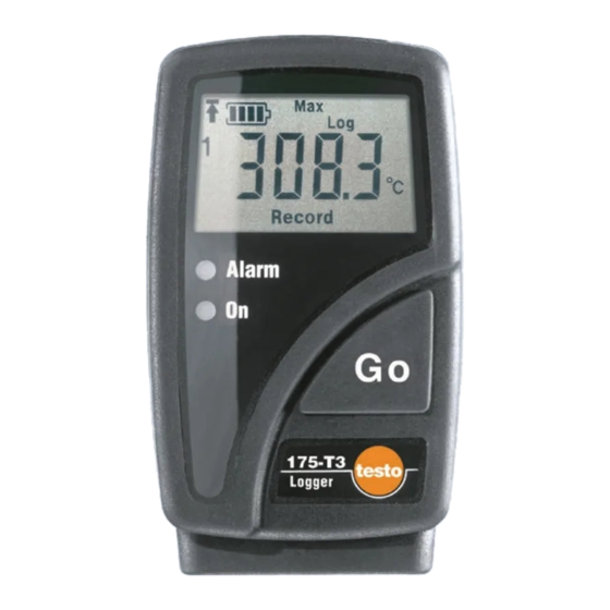
New programming: Switched on Protocol n n ame testo175-{Type}_{Serial number} * testo 175-T3: T/C -Type “K” programmed testo 175-S1: “0 to 10V” programmed testo 175-S2: “0 to 10V” programmed The data logger with the above factory defaults can be used immediately. -
Page 9
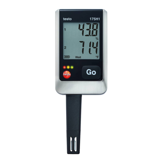
175-S1 testo 175-H1 loggers do not have a display. The following units are shown in the 175 — S S 2 data logger display: testo 175-T1 testo 175-T2 testo 175-T3 testo 175-H2 mV, %, °F, °C and mA. and testo 175-S2… -
Page 10
4 4 . . D D i i s s p p l l a a y y a a n n d d c c o o n n t t r r o o l l e e l l e e m m e e n n t t s s 4.2 L L ED f f unctions The LED functions can be switched on/off via software. testo ComSoft In a a ll m m odes: Alarm led (red LED) The Alarm led flashes three times every 15 seconds if the remaining battery capacity is less than10% (even if Alarm led is deactivated). -
Page 11: Contents
The readings from Start ( All readings ) or From time mark can be read out on the fast printer or the software. testo 575 testo ComSoft The readings from Start ( All readings ) can be read out on the data collector.
-
Page 12: Display
1 Push the data logger into the wall holder. 2 Push the interface onto the wall holder. 3 Secure the unit by connecting the wall holder and the interface using the screw supplied. Testo-Direct info@Testo-Direct.com 1.888.475.5235 www. .com…
-
Page 13
ComSoft connections are printed on the housing! testo 175-S1/S2 The testo 175-S1/S2 data logger is designed for use in electric circuits in measurement technology, automatic control, information technology in process, laboratory and technical systems (0 to 20mA current loop; 0-1V, 0-10V voltage sockets). -
Page 14
7.1 I I nstalling s s oftware In order to program your data logger in accordance with your individual needs, you will need a PC on which the testo ComSoft software is installed. You will find instructions on the installation and operation of the software in the instruction manual. -
Page 15
7.3 S S etting u u p t t he c c onnection 1 Start software. testo ComSoft testo C C omsoft 4 4 : 2 Select IStart > New device . — The New device setup wizard opens. testo C C omsoft 3 3 : 2 Select Instrument >… -
Page 16
PC when the connection is opened. Carry out the following to transmit the readings: Click twice on the title of the protocol (See testo ComSoft software instruction manual). Use o o ne c c onnection f f or s s everal d d ata l l oggers You can connect different data loggers once a connection has been set up. -
Page 17: Programming
Read out any data from the data logger which may exist before programming (See software instruction manual). testo ComSoft Select Start (Comsoft 4) or Instrument (Comsoft 3) > Device control . This function is only activated if the name of the connection is highlighted.
-
Page 18
You can read information from the protocol currently stored in the data logger in the Protocol window. You can choose to display All values and Since time mark . This window is an information window. Programming is not possible. Testo-Direct info@Testo-Direct.com 1.888.475.5235 www. .com… -
Page 19
You cannot change the unit in this window, but in the Settings , window. The lower alarm limit for the channels is entered here. The upper alarm limit for the channels is entered here. Name: Enter a name for the channel here. Testo-Direct info@Testo-Direct.com 1.888.475.5235 www. .com… -
Page 20
Status information on mode and battery capacity are always shown. Enable limit signal output From ComSoft Version 3.4 on, the external alarm signal output testo 581 can be activated if connected to a data logger. Testo-Direct info@Testo-Direct.com 1.888.475.5235 www. -
Page 21
It is only possible to select Date/Time if Date/Time is also selected as Start criterion . If you choose No. of logs an additional field will appear in which the number of measurements required can be entered. Testo-Direct info@Testo-Direct.com 1.888.475.5235 www. -
Page 22
Once the measurement protocol has been opened in the testo software, you can send it by e-mail via testo-Logo > ComSoft Senden (Comsoft 4) or File > Send … by emai . (Comsoft 3). The entered email address and the log are automatically saved in your e-mail. -
Page 23
7.6 C C losing t t he c c onnection 1 Click on the connection you wish to close with your right mouse button in the Data window. 2 Select Close . — The connection to the data logger is closed. Testo-Direct info@Testo-Direct.com 1.888.475.5235 www. .com… -
Page 24
ComSoft 3 Professional (0554.0830) like , but with the following additional features: testo ComSoft 4 Basic — Programming and reading out other Testo instruments such , etc. testo 400 testo 650 — Display and printout as number box, histogram, form, analog… -
Page 25: Changing The Battery
6 Connect the new battery to the data logger`s plug-in connection and place in battery compartment. Only original Testo spare batteries should be used (see 12. A A ccessories/Spare p p arts, P. 34 for Part nos). 7 Remove the jumper from the plug connector.
-
Page 26
1 1 0 0 . . E E r r r r o o r r m m e e s s s s a a g g e e s s If problems occur which are not described here, please contact Testo or your local distributor. For contact data, see back of this document or web page www.testo.com/service-contact… -
Page 27
Battery l l ife …………Typical: 2½ years* ..(Measuring rate: 15 Min., Operating temperature: -10 to +50°C, ……….Display: On, Status led (green LED): Off) * See Chapter 11.7 B B attery l l ife, P. 33 Testo-Direct info@Testo-Direct.com 1.888.475.5235 www. .com… -
Page 28
Battery l l ife …………Typical: 2½ years* ..(Measuring rate: 15 min., Operating temperature: -10 to +50°C, ……….Display: On, Status led (green LED): Off) * See Chapter 11.7 B B attery l l ife, P. 33 Testo-Direct info@Testo-Direct.com 1.888.475.5235 www. .com… -
Page 29
Battery l l ife …………Typical: 2½ years* ..(Measuring rate: 15 Min., Operating temperature: 0 to +50°C, ……….Display: On, Status led (green LED): Off) * See Chapter 11.7 B B attery l l ife, P. 33 Testo-Direct info@Testo-Direct.com 1.888.475.5235 www. .com… -
Page 30
Battery l l ife …………Typical: 2½ years* ..(Measuring rate: 15 min., Operating temperature: -10 to +50°C, ……….Display: On, Status led (green LED): Off) * See Chapter 11.7 B B attery l l ife, P. 33 Testo-Direct info@Testo-Direct.com 1.888.475.5235 www. .com… -
Page 31
Battery …………..Lithium (1/2 AA) Battery l l ifetime…………Typical: 2½ years* ..(Measuring rate: 15 min., Operating temperature: -10 to +50°C, ……….Display: On, Status led (green LED): Off) * See Chapter 11.7 B B attery l l ife, P. 33 Testo-Direct info@Testo-Direct.com 1.888.475.5235 www. .com… -
Page 32
Battery l l ife …………Typical: 2½ years* ..(Measuring rate: 15 min., Operating temperature: -10 to +50°C, ……….Display: On, Status led (green LED): Off) * See Chapter 11.7 B B attery l l ife, P. 33 Testo-Direct info@Testo-Direct.com 1.888.475.5235 www. .com… -
Page 33: Battery Life
Saved readings are not lost if the battery is spent or changed. Requirement: The battery is changed by following the directions in the Instruction manual. Testo-Direct info@Testo-Direct.com 1.888.475.5235 www. .com…
-
Page 34
(1 channel current/voltage, built-in screwed contact socket, 0563 1759 testo 175-S1 wall holder, calibration protocol) testo 175-S2 (1 channel current/voltage, display, built-in screwed contact socket, 0563 1761 wall holder, calibration protocol testo 580 data collector incl. desk-top holder for testo 175/177 data loggers 0554 1778… -
Page 35
Accurate NTC probes for data loggers testo 175-T2 D D e e s s c c r r i i p p t t i i o o n n I I l l l l u u s s t t r r a a t t i i o o n n M M e e a a s s . -
Page 36
Accurate thermocouple probes for data loggers: testo 175-T3 D D e e s s c c r r i i p p t t i i o o n n I I l l l l u u s s t t r r a a t t i i o o n n M M e e a a s s . -
Page 37
N N o o t t e e s s Testo-Direct info@Testo-Direct.com 1.888.475.5235 www. .com… -
Page 38
N N o o t t e e s s Testo-Direct info@Testo-Direct.com 1.888.475.5235 www. .com… -
Page 39
N N o o t t e e s s Testo-Direct info@Testo-Direct.com 1.888.475.5235 www. .com… -
Page 40
Testo-Direct info@Testo-Direct.com 1.888.475.5235 www. .com 0970 1752 en 06 V04.0-0 en-GB…
- Manuals
- Brands
- TESTO Manuals
- Data Loggers
- 175
- Instruction manual
-
Contents
-
Table of Contents
-
Bookmarks
Quick Links
testo 175 · Data loggers
Instruction manual
DataLoggerStore
1.888.
www.
.com
for Data Logging products online at:
Related Manuals for TESTO 175
Summary of Contents for TESTO 175
-
Page 1
175 · Data loggers Instruction manual DataLoggerStore 1.888. www. .com for Data Logging products online at:… -
Page 2
DataLoggerStore 1.888. www. .com for Data Logging products online at:… -
Page 3: Table Of Contents
1 Contents Contents Contents Safety and the environment 2.1. About this document 2.2. Ensure safety 2.3. Protecting the environment Specifications 3.1. 3.2. Technical data First steps 4.1. Unlock the data logger 4.2. Inserting batteries 4.3. Connecting the data logger to PC Display and control elements 5.1.
-
Page 4: Safety And The Environment
2 Safety and the environment Safety and the environment 2.1. About this document > Please read this documentation through carefully and familiarize yourself with the product before putting it to use. Pay particular attention to the safety instructions and warning advice in order to prevent injuries and damage to the products.
-
Page 5: Ensure Safety
The protection class in the technical data specified for the corresponding instrument may otherwise not be reached. > testo 175 T3 : The maximum permissible difference in potential between the sensor inputs is 50 V. Take this into account when using surface sensors with non- isolated thermocouple.
-
Page 6: Specifications
3 Specifications Specifications 3.1. Data loggers testo 175 are used to store and to read out individual readings and measurement series. With testo 175 measurement values are measured, saved and transmitted to the PC via USB cable or SD card, where they can be read out and analysed with the software testo Comfort Software.
-
Page 7
Mini-USB, SD card slot Memory capacity 1 million readings Warranty 24 months, warranty conditions: see website www.testo.com/warranty EC Directive 2004/108/EC, complies with the EN standard12830 testo 175 T2 (0572 1752) Feature Values Measurement Temperature (°C/°F) parameter Sensor type NTC temperature sensor internal and… -
Page 8
Interface Mini-USB, SD card slot Memory capacity 1 million readings Warranty 24 moths, warranty conditions: see website www.testo.com/warranty EC Directive 2004/108/EC, complies with the EN standard12830 Please note that, according to EN 12830, this instrument must be regularly checked and calibrated as specified in EN 13486 (recommendation: every year) Contact us for more information. -
Page 9
3 Specifications testo 175 T3 (0572 1753) Feature Values Measurement Temperature (°C/°F) parameter Sensor type 2 thermocouples (type K or T) external Measurement -50 to +400 °C (type T) range -50 to +1000 °C (type K) Instrument ±0.5 °C (-50 to +70 °C) ± 1 digit accuracy ±… -
Page 10
3 Specifications testo 175 H1 (0572 1754) Feature Values Measurement Temperature (°C/°F), moisture (%rF parameter /%RH/ °Ctd/ g/m Sensor type NTC temperature sensor, capacitive humidity sensor Number of 2x internal (stubs) measuring channels Measuring -20 to +55 °C ranges -40 to +50 °Ctd… -
Page 11
Interface Mini-USB, SD card slot Memory capacity 1 million readings Warranty 24 months, warranty conditions: see website www.testo.com/warranty EC Directive 2004/108/EC Battery life The programming windows of the software provide you with typical guide values for the expected lifetime of the battery. -
Page 12: First Steps
4 First steps data logger is switched off when a critical voltage level has been reached. It may therefore happen that: • readings are still recorded, even though the battery capacity reading says «empty». • the measurement program is stopped, even though the battery capacity reading just before indicated a still remaining battery capacity.
-
Page 13: Inserting Batteries
The software is available in the Internet as a free download requiring registration: www.testo.com/download-center. The instructions for the installation and operation of the software can be found in the testo Comfort Software Basic 5 instruction manual, which can be downloaded together with the software.
-
Page 14: Display And Control Elements
5 Display and control elements 4. Open the cover. 5. Plug the USB cable into the Mini USB port (1). 6. Configure the data logger, see separate operating instructions testo Comfort Software. Display and control elements 5.1. Display The display function can be switched on/off via the software testo Comfort Software.
-
Page 15
5 Display and control elements testo 175 T1 1 Highest saved reading 2 Lowest saved reading 3 Reading 4 Units 5 Measurement program over 6 Measurement program running 7 Wait for start of measurement program 8 Start criterion Date/ Time programmed… -
Page 16
11 Upper alarm value • Flashes: programmed alarm value is shown • Lights: programmed alarm values were exceeded testo 175 T2, testo 175 T3, testo 175 H1 1 Reading channel 1 2 Units channel 1 3 Reading channel 2 4 Units channel 2… -
Page 17: Led
5 Display and control elements Icon Capacity <30 days > Read out data and change battery (see Reading out measurement data page 24). 10 Lower limit value channel 2: • Flashes: programmed alarm value is shown • Lights: programmed alarm values were fallen short 11 Upper limit value channel 2: •…
-
Page 18: Key Functions
5 Display and control elements Representation Explanation Yellow LED Instrument changes from Wait-mode to flashes three Rec-mode. times Yellow LED Instrument is in Rec-mode flashes three times when pressing the button Green and Instrument is in End-mode yellow LED flash three times when pressing the button.
-
Page 19: Using The Product
> Ensure correct positioning of the sensor to avoid disturbing influences affecting the measurement. > testo 175 T3: Always make sure that you connect the sensor configured (via the software testo Comfort Software) to the individual sockets. The numbers of the connections are printed on the housing.
-
Page 20: Menu Overview
6 Using the product 6.3. Menu overview The menu overview shows exemplary display representations of the data logger testo 175-T2. The display must be switched on to be able to show the corresponding indications. This is accomplished with the software testo Comfort Software.
-
Page 21
6 Using the product Wait mode: Start criterion is programmed, but not yet fulfilled. ① Last ② Upper alarm value reading Start criterion Start criterion key start / PC Date/Time start ③ Lower alarm value ④ Battery capacity in days (see Fig. -
Page 22
6 Using the product Rec mode: Start criterion was fulfilled, data logger saves readings ① Last reading ② Highest reading ③ Lowest reading ④ Upper alarm value ⑤ Lower alarm value ⑥ Battery capacity in days Last reading (see Fig. ① Rec mode) DataLoggerStore 1.888. -
Page 23: Mounting The Wall Bracket
6 Using the product End mode: Measurement program finished (stop criterion reached – memory full or number of readings) depending on programming ① Last reading ② Highest reading ③ Lowest reading ④ Upper alarm value ⑤ Lower alarm value ⑥ Battery capacity in days Last reading (see Fig.
-
Page 24: Securing The Data Logger
6 Using the product 4. Fasten the wall bracket with suitable screws. 6.5. Securing the data logger ✓ The wall bracket has been mounted. 1. Slide the data logger into the wall bracket (1). 2. Push the locking pin (2) through the holes in the wall bracket.
-
Page 25: Maintaining The Product
3. Push the SD card into the SD card slot (2). The display shows (testo 175 T1) or Sd CArd (testo 175 T2, testo 175 T3, testo 175 H1). 4. Hold [Go] depressed for longer than 2 seconds. The display shows…
-
Page 26
9. Connect the data logger to the PC with a USB cable. 10. Start the software testo Comfort Software and set up a connection to the data logger. 11. Reconfigure the data logger or load the old, saved configuration, see separate operating instructions testo Comfort Software. -
Page 27: Cleaning The Instrument
> Reprogram the data logger via the software. — — — — Sensor of data logger defective. appears in the display. > Contact your dealer or the Testo Customer Service. DataLoggerStore 1.888. www. .com for Data Logging products online at:…
-
Page 28: Accessories And Spare Parts
8 Tips and assistance If you have any questions please contact your local dealer or the Testo Customer Service. You find contact data on the back of this document or in the Internet under www.testo.com/service-contact. 8.2. Accessories and spare parts Description Article no.
-
Page 29
DataLoggerStore 1.888. www. .com for Data Logging products online at:… -
Page 30
0970 1759 en 04 DataLoggerStore 1.888. www. .com for Data Logging products online at:…
-
Page 1
175 · Datenlogger Bedienungsanleitung testo 175 · Data loggers Instruction manual testo 175 · Enregistreur de données Mode d’emploi testo 175 · Data logger Manual de instrucciones testo 175 · Data logger Istruzioni per l’uso testo 175 · Datalogger… -
Page 2
Deutsch …………….3 English …………….31 Français …………….57 Español …………….83 Italiano …………….111 Nederlands…………..137 Pos: 1 /TD/— Seitenwechsel — @ 0mod_1173774430601_0.doc @ 281 @… -
Page 3: Table Of Contents
1 Inhalt Pos: 2 /TD/Überschriften/1. Inhalt @ 0mod_1177587817070_6.doc @ 1241 @ 1 Inhalt Inhalt Sicherheit und Umwelt 2.1. Zu diesem Dokument 2.2. Sicherheit gewährleisten 2.3. Umwelt schützen Leistungsbeschreibung 3.1. Verwendung Technische Daten Erste Schritte 5.1. Datenlogger entsichern 5.2. Batterien einlegen 5.3.
-
Page 4: Sicherheit Und Umwelt
2 Sicherheit und Umwelt Pos: 3 /TD/Überschriften/2. Sicherheit und Umwelt @ 0mod_1173774719351_6.doc @ 290 @ 1 Sicherheit und Umwelt Pos: 4 /TD/Überschriften/2.1 Zu diesem Dokument @ 0mod_1173775252351_6.doc @ 344 @ 2 2.1. Zu diesem Dokument Pos: 5 /TD/Sicherheit und Umwelt/Zu diesem Dokument/Verwendung/Verwendung (Standard) @ 0mod_1173775068554_6.doc @ 335 @ 5 Verwendung >…
-
Page 5: Sicherheit Gewährleisten
Daten vorgegebenen Parameter. Wenden Sie keine Gewalt an. Pos: 9 /TD/Sicherheit und Umwelt/Sicherheit gewährleisten/testo 174-175/spannungsführende Teile 175-176 @ 7mod_1282811328700_6.doc @ 71292 @ > Messen Sie mit dem Gerät niemals an oder in der Nähe von spannungsführenden Teilen! Pos: 10 /TD/Sicherheit und Umwelt/Sicherheit gewährleisten/testo 174-175/Blindstopfen @ 6mod_1274956302912_6.doc @ 61914 @…
-
Page 6: Umwelt Schützen
Über die Software können die Datenlogger auch individuell programmiert werden. Anwendungsbeispiele testo 175 T1 und testo 175 T2 sind optimal geeignet für die Temperaturmessung in Kühlschränken, Gefrierschränken, Kühlräumen und Kühlregalen. testo 175 T3 zeichnet zwei Temperaturen gleichzeitig auf und eignet sich damit z.
-
Page 7: Technische Daten
4 Technische Daten Technische Daten Pos: 20 /TD/Leistungsbeschreibung/Technische Daten/testo 175 T1 @ 6mod_1274950278224_6.doc @ 61786 @ 5 testo 175 T1 (0572 1751) Eigenschaft Werte Messgröße Temperatur (°C/°F) Fühlertyp NTC-Temperatursensor intern Messbereich -35 bis +55 °C Genauigkeit System ±0,5 °C (-35 bis +55 °C) ± 1 Digit Auflösung…
-
Page 8
4 Technische Daten Pos: 21 /TD/Leistungsbeschreibung/Technische Daten/testo 175 T2 @ 6mod_1274950304801_6.doc @ 61818 @ 5 testo 175 T2 (0572 1752) Eigenschaft Werte Messgröße Temperatur (°C/°F) Fühlertyp NTC-Temperatursensor intern und extern Messbereich -35 bis +55 °C intern -40 bis +120 °C extern Genauigkeit System ±0,5 °C (-35 bis +55 °C) ±… -
Page 9
4 Technische Daten Pos: 22 /TD/Leistungsbeschreibung/Technische Daten/testo 175 T3 @ 6mod_1274950324191_6.doc @ 61850 @ 5 testo 175 T3 (0572 1753) Eigenschaft Werte Messgröße Temperatur (°C/°F) Fühlertyp 2 Thermoelemente (Typ K oder T) extern Messbereich -40 bis +400 °C (Typ T) -50 bis +1000 °C (Typ K) -
Page 10
4 Technische Daten testo 175 H1 (0572 1754) Eigenschaft Werte Messgröße Temperatur (°C/°F), Feuchte (%rF / %RH/ °Ctd/ g/m Fühlertyp NTC-Temperatursensor, kapazitiver Feuchtesensor Anzahl der 2x intern (Stummel) Messkanäle Messbereiche -20 bis +55 °C -40 bis +50 °Ctd 0 bis 100 %rF (nicht betauende Atmosphäre) -
Page 11
4 Technische Daten Pos: 24 /TD/Leistungsbeschreibung/Technische Daten/Hinweis Batteriestandzeit @ 6mod_1274958762415_6.doc @ 62010 @ 5 Batteriestandzeit In den Programmierfenstern der Software erhalten Sie typische Richtwerte zur voraussichtlichen Lebensdauer der Batterie. Diese wird auf Basis folgender Faktoren errechnet: • Messtakt • Anzahl angeschlossener Fühler Da die Batteriestandzeit noch von vielen weiteren Faktoren abhängig ist, sind die berechneten Daten nur Richtwerte. -
Page 12: Erste Schritte
5 Erste Schritte Pos: 25 /TD/Überschriften/5. Erste Schritte @ 0mod_1173774895039_6.doc @ 317 @ 1 Erste Schritte Pos: 26 /TD/Erste Schritte/testo 175/Datenlogger entsichern @ 7mod_1288082730183_6.doc @ 72502 @ 5.1. Datenlogger entsichern 1. Schloss mit Schlüssel (1) öffnen. 2. Schloss (2) aus Sicherungsstift entfernen.
-
Page 13: Datenlogger An Pc Anschließen
5. Batteriefachabdeckung auf das Batteriefach legen. 6. Schrauben anziehen. Auf dem Display erscheint rST. Pos: 28 /TD/Erste Schritte/testo 175/Datenlogger an PC anschließen Hardware @ 6mod_1275476329286_6.doc @ 62372 @ 5.3. Datenlogger an PC anschließen Für testo ComSoft 5 Basic: Die Software ist als kostenloser registrierungspflichtiger Download im Internet erhältlich:…
-
Page 14: Anzeige- Und Bedienelemente
6 Anzeige- und Bedienelemente Pos: 29 /TD/Produktbeschreibung/Übersicht/testo 175/Anzeige- und Bedienelemente, Display @ 6mod_1274956795162_6.doc @ 61947 @ Anzeige- und Bedienelemente 6.1. Display Die Display-Funktion kann über die Software testo ComSoft ein-/ausgeschaltet werden. Je nach Betriebszustand können im Display unter- schiedliche Informationen angezeigt werden. Eine detaillierte Darstellung der abrufbaren Infor- mationen finden Sie unter Menüübersicht, Seite…
-
Page 15
Alarmwert wurde unterschritten 11 oberer Alarmwert • blinkt: programmierter Alarmwert wird angezeigt • leuchtet: programmierter Alarmwert wurde überschritten testo 175 T2, testo 175 T3, testo 175 H1 1 Messwert Kanal 1 2 Einheiten Kanal 1 3 Messwert Kanal 2… -
Page 16
6 Anzeige- und Bedienelemente 4 Einheiten Kanal 2 5 Messprogramm beendet 6 Messprogramm läuft 7 Warten auf Start des Messprogramms 8 Startkriterium Datum/ Uhrzeit programmiert 9 Batteriekapazität Symbol Kapazität >151 Tage <150 Tage <90 Tage <60 Tage <30 Tage > Daten auslesen und Batterie wechseln (siehe Messdaten auslesen, Seite 24). -
Page 17: Led
Gerät befindet sich im bei Tastendruck Wait-Modus. Grüne LED blinkt fünfmal Durch langes Gedrückthalten bei langem Tastendruck der GO-Taste wurde eine Zeitmarke gesetzt. Grüne, gelbe und rote Batterie wurde gewechselt. LED blinken nacheinander Pos: 30 /TD/Produktbeschreibung/Übersicht/testo 175/Tastenfunktionen @ 6mod_1275477413448_6.doc @ 62404 @…
-
Page 18: Tastenfunktionen
6 Anzeige- und Bedienelemente 6.3. Tastenfunktionen Eine detaillierte Darstellung der Displayanzeigen finden Sie im unter Menüübersicht, Seite 20. ✓ Gerät befindet sich im Betriebszustand Wait Startkriterium Tastenstart ist programmiert. > [GO] ca. 3 Sekunden lang drücken, um das Mess- programm zu starten. Das Messprogramm startet und im Display erscheint Rec.
-
Page 19: Produkt Verwenden
7 Produkt verwenden Pos: 31 /TD/Überschriften/6. Produkt verwenden @ 0mod_1173774928554_6.doc @ 326 @ 1 Produkt verwenden Pos: 32 /TD/Erste Schritte/testo 175/Fühler anschließen @ 6mod_1274957942556_6.doc @ 61979 @ 7.1. Fühler anschließen Beachten Sie beim Anschluss von Fühlern an den Datenlogger und an die Messstellen die folgenden Punkte: >…
-
Page 20: Menüübersicht
Displayansichten des Datenloggers testo 175-T2 dargestellt. Das Display muss eingeschaltet sein, damit die entsprechenden Anzeigen im Display dargestellt werden. Dies erfolgt über die Software testo ComSoft. Die Anzeige im Display wird entsprechend der programmierten Messrate aktualisiert. Es werden nur Messwerte von aktiven Kanälen angezeigt.
-
Page 21
7 Produkt verwenden Wait-Modus: Startkriterium ist programmiert, aber noch nicht erfüllt ① Letzter ② Oberer Alarmwert Messwert Startkriterium Startkriterium Tastenstart / PC- Datum/Uhrzeit Start ③ Unterer Alarmwert ④ Batteriekapazität in Tagen (siehe Abbildung ① Wait-Modus) Letzter Messwert Messwert wird nicht gespeichert… -
Page 22
– bis Speicher voll oder Anzahl Werte) je nach Programmierung ① Letzter Messwert ② Höchster Messwert ③ Niedrigster Messwert ④ Oberer Alarmwert ⑤ Unterer Alarmwert ⑥ Batteriekapazität in Tagen Letzter Messwert (siehe Abbildung ①) Pos: 35 /TD/Produkt verwenden/testo 175/Wandhalterung montieren @ 6mod_1276691151158_6.doc @ 62633 @… -
Page 23: Wandhalterung Montieren
Befestigung vorbereiten (z. B. Loch bohren, Dübel setzen). 4. Wandhalterung mit Hilfe passender Schrauben befestigen. Pos: 36 /TD/Erste Schritte/testo 175/Datenlogger sichern @ 6mod_1275475596653_6.doc @ 62340 @ 7.5. Datenlogger sichern ✓ Wandhalterung ist montiert. 1. Datenlogger in die Wandhalterung schieben (1).
-
Page 24: Messdaten Auslesen
Verwenden Sie dazu am besten ein Münzstück. 3. Deckel öffnen. 4. USB-Kabel in den Mini-USB-Anschluss (1) schieben. 5. Datenlogger auslesen und ausgelesene Daten weiter- bearbeiten, siehe separate Bedienungsanleitung testo ComSoft. Über SD-Karte 1. Schraube an der rechten Seite des Datenloggers lösen.
-
Page 25
7 Produkt verwenden (testo 175 T1) bzw. Sd CArd (testo 175 T2, testo 175 T3, testo 175 H1) wird im Display angezeigt. [Go] länger als 2 Sekunden gedrückt halten. (testo 175 T1) bzw. COPY (testo 175 T2, testo 175 T3, testo 175 H1) wird im Display angezeigt. -
Page 26: Produkt Instand Halten
8 Produkt instand halten Produkt instand halten Pos: 39 /TD/Produkt instand halten/testo 175/Batterien wechseln @ 6mod_1275474943888_6.doc @ 62276 @ 8.1. Batterien wechseln Durch den Batteriewechsel wird das laufende Messprogramm gestoppt. Die gespeicherten Messdaten bleiben aber erhalten. 1. Gespeicherte Messdaten auslesen, siehe Messdaten auslesen, Seite 24.
-
Page 27: Gerät Reinigen
11. Datenlogger neu konfigurieren bzw. die alte gespeicherte Konfiguration aufspielen, siehe separate Bedienungsanleitung testo ComSoft. Der Datenlogger ist wieder einsatzbereit. Pos: 40 /TD/Produkt instand halten/testo 174-neu/Gerät reinigen @ 5mod_1267614722447_6.doc @ 59662 @ 8.2. Gerät reinigen ACHTUNG Beschädigung des Sensors! > Achten Sie darauf, dass bei der Reinigung keine Flüssigkeit in das Innere des Gehäuses gelangt.
-
Page 28: Tipps Und Hilfe
9 Tipps und Hilfe Tipps und Hilfe Pos: 42 /TD/Überschriften/8.1 Fragen und Antworten @ 0mod_1177402017078_6.doc @ 1091 @ 9.1. Fragen und Antworten Pos: 43 /TD/Tipps und Hilfe/Fragen und Antworten/testo 175 @ 6mod_1275471058687_6.doc @ 62115 @ Frage Mögliche Ursachen / Lösung FULL erscheint auf SD-Karte hat nicht genügend…
-
Page 29: Zubehör Und Ersatzteile
9 Tipps und Hilfe Pos: 44 /TD/Überschriften/8.2 Zubehör und Ersatzteile @ 0mod_1177402058734_6.doc @ 1100 @ 2 9.2. Zubehör und Ersatzteile Pos: 45 /TD/Tipps und Hilfe/Zubehör und Ersatzteile/testo 175 @ 6mod_1275471350081_6.doc @ 62147 @ Beschreibung Artikel-Nr. Wandhalterung (schwarz) mit Schloss 0554 1702…
-
Page 30
9 Tipps und Hilfe… -
Page 31: Contents
1 Contents Contents Contents Safety and the environment 2.1. About this document 2.2. Ensure safety 2.3. Protecting the environment Specifications 3.1. Technical data First steps 5.1. Unlock the data logger 5.2. Inserting batteries 5.3. Connecting the data logger to PC Display and control elements 6.1.
-
Page 32: Safety And The Environment
2 Safety and the environment Pos: 3 /TD/Überschriften/2. Sicherheit und Umwelt @ 0mod_1173774719351_79.doc @ 292 @ 1 Safety and the environment Pos: 4 /TD/Überschriften/2.1 Zu diesem Dokument @ 0mod_1173775252351_79.doc @ 346 @ 2 2.1. About this document Pos: 5 /TD/Sicherheit und Umwelt/Zu diesem Dokument/Verwendung/Verwendung (Standard) @ 0mod_1173775068554_79.doc @ 337 @ 5 >…
-
Page 33: Ensure Safety
Do not use any force. Pos: 9 /TD/Sicherheit und Umwelt/Sicherheit gewährleisten/testo 174-175/spannungsführende Teile 175-176 @ 7mod_1282811328700_79.doc @ 71293 @ > Never use the instrument to measure on or near live parts.
-
Page 34: Specifications
Pos: 17 /TD/Überschriften/3.1 Verwendung @ 0mod_1176211016437_79.doc @ 695 @ 2 3.1. Use Pos: 18 /TD/Leistungsbeschreibung/Verwendung/testo 175 @ 6mod_1274950423499_79.doc @ 61883 @ 5 Data loggers testo 175 are used to store and to read out individual readings and measurement series. With testo 175 measurement values are measured, saved…
-
Page 35: Technical Data
4 Technical data Technical data Pos: 20 /TD/Leistungsbeschreibung/Technische Daten/testo 175 T1 @ 6mod_1274950278224_79.doc @ 61787 @ 5 testo 175 T1 (0572 1751) Feature Values Measurement Temperature (°C/°F) parameter Sensor type NTC temperature sensor internal Measurement range -35 to +55 °C System accuracy ±0.5 °C (-35 to +55 °C) ±…
-
Page 36
4 Technical data Pos: 21 /TD/Leistungsbeschreibung/Technische Daten/testo 175 T2 @ 6mod_1274950304801_79.doc @ 61819 @ 5 testo 175 T2 (0572 1752) Feature Values Measurement Temperature (°C/°F) parameter Sensor type NTC temperature sensor internal and external Measurement range -35 to +55 °C internal -40 to +120 °C external… -
Page 37
4 Technical data Pos: 22 /TD/Leistungsbeschreibung/Technische Daten/testo 175 T3 @ 6mod_1274950324191_79.doc @ 61851 @ 5 testo 175 T3 (0572 1753) Feature Values Measurement Temperature (°C/°F) parameter Sensor type 2 thermocouples (type K or T) external Measurement -40 to +400 °C (type T) range -50 to +1000 °C (type K) -
Page 38
4 Technical data testo 175 H1 (0572 1754) Feature Values Measurement Temperature (°C/°F), moisture parameter (%rF /%RH/ °Ctd/ g/m Sensor type NTC temperature sensor, capacitive humidity sensor Number of measuring 2x internal (stubs) channels Measuring ranges -20 to +55 °C -40 to +50 °Ctd… -
Page 39
4 Technical data Pos: 24 /TD/Leistungsbeschreibung/Technische Daten/Hinweis Batteriestandzeit @ 6mod_1274958762415_79.doc @ 62012 @ 5 Battery life The programming windows of the software provide you with typical guide values for the expected lifetime of the battery. This lifetime is calculated on the basis of the following factors: •… -
Page 40: First Steps
5 First steps Pos: 25 /TD/Überschriften/5. Erste Schritte @ 0mod_1173774895039_79.doc @ 319 @ 1 First steps Pos: 26 /TD/Erste Schritte/testo 175/Datenlogger entsichern @ 7mod_1288082730183_79.doc @ 72503 @ 5.1. Unlock the data logger 1. Open the lock with the key (1).
-
Page 41: Connecting The Data Logger To Pc
6. Tighten the screws. The display shows rST. Pos: 28 /TD/Erste Schritte/testo 175/Datenlogger an PC anschließen Hardware @ 6mod_1275476329286_79.doc @ 62373 @ 5.3. Connecting the data logger to PC For testo ComSoft 5 Basic: The software is available in the Internet as a free download requiring registration: www.testo.com/download-center.
-
Page 42: Display And Control Elements
6 Display and control elements Pos: 29 /TD/Produktbeschreibung/Übersicht/testo 175/Anzeige- und Bedienelemente, Display @ 6mod_1274956795162_79.doc @ 61948 @ Display and control elements 6.1. Display The display function can be switched on/off via the software testo ComSoft. Depending on the operating status, various information may be shown in the display.
-
Page 43
11 Upper alarm value • Flashes: programmed alarm value is shown • Lights: programmed alarm values were exceeded testo 175 T2, testo 175 T3, testo 175 H1 1 Reading channel 1 2 Units channel 1 3 Reading channel 2 4 Units channel 2… -
Page 44
6 Display and control elements 5 Measurement program over 6 Measurement program running 7 Wait for start of measurement program 8 Start criterion Date/ Time programmed 9 Battery capacity Icon Capacity >151 days <150 days <90 days <60 days <30 days >… -
Page 45: Led
Green LED flashes five Long pressing of the GO button times when pressing the has set a time mark. button Green, yellow and red The battery has been changed. LED flash in succession Pos: 30 /TD/Produktbeschreibung/Übersicht/testo 175/Tastenfunktionen @ 6mod_1275477413448_79.doc @ 62405 @…
-
Page 46: Key Functions
6 Display and control elements 6.3. Key functions A detailed representation of the display readings can be found under Menu overview, page 48. ✓ Instrument in operating status Wait and start criterion Button start programmed. > Press [GO] for approx. 3 seconds to start the measurement program.
-
Page 47: Using The Product
7 Using the product Pos: 31 /TD/Überschriften/6. Produkt verwenden @ 0mod_1173774928554_79.doc @ 328 @ 1 Using the product Pos: 32 /TD/Erste Schritte/testo 175/Fühler anschließen @ 6mod_1274957942556_79.doc @ 61981 @ 7.1. Connecting a sensor Observe the following points when connecting sensors to data logger and measuring points.
-
Page 48: Menu Overview
7 Using the product 7.3. Menu overview The menu overview shows exemplary display representations of the data logger testo 175-T2. The display must be switched on to be able to show the corresponding indications. This is accomplished with the software testo ComSoft.
-
Page 49
7 Using the product Wait mode: Start criterion is programmed, but not yet fulfilled. ① Last ② Upper alarm value reading Start criterion key Start criterion start / PC start Date/Time ③ Lower alarm value ④ Battery capacity in days (see Fig. -
Page 50
① Last reading ② Highest reading ③ Lowest reading ④ Upper alarm value ⑤ Lower alarm value ⑥ Battery capacity in days Last reading (see Fig. ①) Pos: 35 /TD/Produkt verwenden/testo 175/Wandhalterung montieren @ 6mod_1276691151158_79.doc @ 62634 @… -
Page 51: Mounting The Wall Bracket
3. Prepare the fastening location in accordance with the fastening material (e.g. drill hole, insert wall plugs). 4. Fasten the wall bracket with suitable screws. Pos: 36 /TD/Erste Schritte/testo 175/Datenlogger sichern @ 6mod_1275475596653_79.doc @ 62341 @ 7.5. Securing the data logger ✓ The wall bracket has been mounted.
-
Page 52: Reading Out Measurement Data
1. Loosen the screw on the right side of the data logger. Use a coin for this purpose. 2. Open the cover. 3. Push the SD card into the SD card slot (2). The display shows (testo 175 T1) or Sd CArd (testo 175 T2, testo 175 T3, testo 175 H1).
-
Page 53: Maintaining The Product
ComSoft. Pos: 38 /TD/Überschriften/7. Produkt instand halten @ 0mod_1173789831362_79.doc @ 397 @ 1 Maintaining the product Pos: 39 /TD/Produkt instand halten/testo 175/Batterien wechseln @ 6mod_1275474943888_79.doc @ 62277 @ 8.1. Changing batteries The battery change stops the currently running measurement program.
-
Page 54: Cleaning The Instrument
11. Reconfigure the data logger or load the old, saved configuration, see separate operating instructions testo ComSoft. The data logger is once again ready for use. Pos: 40 /TD/Produkt instand halten/testo 174-neu/Gerät reinigen @ 5mod_1267614722447_79.doc @ 59663 @ 8.2. Cleaning the instrument CAUTION Damage to the sensor! >…
-
Page 55: Tips And Assistance
9 Tips and assistance Tips and assistance Pos: 42 /TD/Überschriften/8.1 Fragen und Antworten @ 0mod_1177402017078_79.doc @ 1093 @ 9.1. Questions and answers Pos: 43 /TD/Tipps und Hilfe/Fragen und Antworten/testo 175 @ 6mod_1275471058687_79.doc @ 62116 @ Question Possible causes / solution FULL…
-
Page 56: Accessories And Spare Parts
9 Tips and assistance 9.2. Accessories and spare parts Pos: 45 /TD/Tipps und Hilfe/Zubehör und Ersatzteile/testo 175 @ 6mod_1275471350081_79.doc @ 62148 @ Description Article no. Wall bracket (black) with lock 0554 1702 Mini USB cable to connect the data 0449 0047…
-
Page 57: Sommaire
1 Sommaire Sommaire Sommaire Sécurité et environnement 2.1. Concernant ce document 2.2. Assurer la sécurité 2.3. Protéger l’environnement Description 3.1. Utilisation Caractéristiques techniques Prise en main 5.1. Déverrouiller l’enregistreur de données 5.2. Mise en place des piles 5.3. Raccorder l’enregistreur de données au PC 67 Affichage et éléments de commande 6.1.
-
Page 58: Sécurité Et Environnement
2 Sécurité et environnement Sécurité et environnement Pos: 4 /TD/Überschriften/2.1 Zu diesem Dokument @ 0mod_1173775252351_201.doc @ 347 @ 2 2.1. Concernant ce document Pos: 5 /TD/Sicherheit und Umwelt/Zu diesem Dokument/Verwendung/Verwendung (Standard) @ 0mod_1173775068554_201.doc @ 338 @ 5 Utilisation > Veuillez, attentivement, prendre connaissance de cette documentation et familiarisez-vous avec le produit avant de l’utiliser.
-
Page 59: Assurer La Sécurité
Ne faites pas usage de la force. Pos: 9 /TD/Sicherheit und Umwelt/Sicherheit gewährleisten/testo 174-175/spannungsführende Teile 175-176 @ 7mod_1282811328700_201.doc @ 71294 @ > Ne jamais mesurer avec cet appareil sur ou à proximité de pièces sous tension ! Pos: 10 /TD/Sicherheit und Umwelt/Sicherheit gewährleisten/testo 174-175/Blindstopfen @ 6mod_1274956302912_201.doc @ 61916 @…
-
Page 60: Protéger L’environnement
Pos: 17 /TD/Überschriften/3.1 Verwendung @ 0mod_1176211016437_201.doc @ 696 @ 2 3.1. Utilisation Pos: 18 /TD/Leistungsbeschreibung/Verwendung/testo 175 @ 6mod_1274950423499_201.doc @ 61884 @ 5 Les enregistreurs de données testo 175 sont utilisés pour mémoriser et extraire les différentes valeurs et séries de mesure.
-
Page 61: Caractéristiques Techniques
4 Caractéristiques techniques Caractéristiques techniques Pos: 20 /TD/Leistungsbeschreibung/Technische Daten/testo 175 T1 @ 6mod_1274950278224_201.doc @ 61788 @ 5 testo 175 T1 (0572 1751) Propriété Valeurs Grandeur Température (°C / °F) Type de capteur Capteur de température NTC interne Plage de mesure -35 à…
-
Page 62
4 Caractéristiques techniques Pos: 21 /TD/Leistungsbeschreibung/Technische Daten/testo 175 T2 @ 6mod_1274950304801_201.doc @ 61820 @ 5 testo 175 T2 (0572 1752) Propriété Valeurs Grandeur Température (°C / °F) Capteur de température NTC Type de capteur interne et externe Plage de mesure -35 à… -
Page 63
4 Caractéristiques techniques Pos: 22 /TD/Leistungsbeschreibung/Technische Daten/testo 175 T3 @ 6mod_1274950324191_201.doc @ 61852 @ 5 testo 175 T3 (0572 1753) Propriété Valeurs Grandeur Température (°C / °F) Type de capteur 2 thermocouples (type K ou T) externes Plage de mesure -40 à… -
Page 64
4 Caractéristiques techniques testo 175 H1 (0572 1754) Propriété Valeurs Grandeur Température (°C/°F), Humidité (%rF /%RH/ °Ctd/ g/m Type de capteur Capteur de température NTC, capteur d’humidité capacitif Nombre de canaux de 2x interne (dans la mesure prolongation) Plages de mesure -20 à… -
Page 65
4 Caractéristiques techniques Pos: 24 /TD/Leistungsbeschreibung/Technische Daten/Hinweis Batteriestandzeit @ 6mod_1274958762415_201.doc @ 62013 @ 5 Durée de vie des piles Dans les fenêtres de programmation du logiciel, vous recevez des valeurs indicatives typiques concernant la longévité prévisible des piles. Elle est calculée sur la base des facteurs suivants : •… -
Page 66: Prise En Main
5 Prise en main Pos: 25 /TD/Überschriften/5. Erste Schritte @ 0mod_1173774895039_201.doc @ 320 @ 1 Prise en main Pos: 26 /TD/Erste Schritte/testo 175/Datenlogger entsichern @ 7mod_1288082730183_201.doc @ 72504 @ 5.1. Déverrouiller l’enregistreur de données 1. Ouvrir le cadenas avec la clé (1).
-
Page 67: Raccorder L’enregistreur De Données Au Pc
5. Poser le couvercle du compartiment à piles. 6. Serrer les vis. s’affiche à l’écran. Pos: 28 /TD/Erste Schritte/testo 175/Datenlogger an PC anschließen Hardware @ 6mod_1275476329286_201.doc @ 62374 @ 5.3. Raccorder l’enregistreur de données au PC Pour testo ComSoft 5 Basic: Le logiciel est disponible gratuitement avec enregistrement par téléchargement sur l’internet :…
-
Page 68: Affichage Et Éléments De Commande
6 Affichage et éléments de commande Pos: 29 /TD/Produktbeschreibung/Übersicht/testo 175/Anzeige- und Bedienelemente, Display @ 6mod_1274956795162_201.doc @ 61949 @ Affichage et éléments de commande 6.1. Ecran La fonction écran peut être alumée/éteinte avec le logiciel testo ComSoft. Les informations affichées à l’écran dépendent de l’état de fonctionnement.
-
Page 69
11 Seuil d’alarme supérieur • clignote : le seuil d’alarme programmé s’affiche • allumé : seuil d’alarme programmé a été dépassé testo 175 T2, testo 175 T3, testo 175 H1 1 Valeur canal 1 2 Unités canal 1 3 Valeur canal 2… -
Page 70
6 Affichage et éléments de commande 4 Unités canal 2 5 Programme de mesure terminé 6 Programme de mesure en cours 7 Attendre le démarrage du programme de mesure 8 Critère de départ date/heure programmé 9 Capacité de la pile Symbole Capacité… -
Page 71: Del
En appuyant longtemps sur la fois à la pression longue touche GO, un repère temporel de la touche a été placé. DEL verte, jaune, rouge Changement de la pile. clignotent les unes après les autres Pos: 30 /TD/Produktbeschreibung/Übersicht/testo 175/Tastenfunktionen @ 6mod_1275477413448_201.doc @ 62406 @…
-
Page 72: Fonctions Des Touches
6 Affichage et éléments de commande 6.3. Fonctions des touches Une représentation détaillée des affichages figure dans Vue d’ensemble du menu, page 74. ✓ L’appareil se trouve dans l’état de fonctionnement Wait et le critère de départ Démarrage par touche est programmé.
-
Page 73: Utilisation Du Produit
> Veillez à la bonne position du capteur afin d’éviter les perturbations sur les mesures. > testo 175 T3: Veillez à raccorder à la douille le capteur configuré (à travers le logiciel testo ComSoft). Les numéros des raccords sont imprimés sur le boitier.
-
Page 74: Vue D’ensemble Du Menu
7 Utilisation du produit 7.3. Vue d’ensemble du menu Dans la vue d’ensemble du menu, les affichages à l’écran de l’enregistreur de donnés testo 175-T2 sont représentées à titre d’exemple. L’écran doit être allumé afin que les différents affichages puissent apparaitre à l’écran. Cela se fait à…
-
Page 75
7 Utilisation du produit Mode Wait : Le critère de départ est programmé mais pas encore satisfait ① dernière ② seuil d’alarme supérieur valeur Critère de départ Critère de départ Démarrage par date/heure touche / Démarrage par ③ seuil d’alarme inférieur ④… -
Page 76
① dernière valeur ② valeur maximale ③ valeur minimale ④ seuil d’alarme supérieur ⑤ seuil d’alarme inférieur ⑥ capacité des piles en jours Dernière valeur (voir figure ①) Pos: 35 /TD/Produkt verwenden/testo 175/Wandhalterung montieren @ 6mod_1276691151158_201.doc @ 62635 @… -
Page 77: Montage Du Support Mural
3. Préparer le point de fixation en fonction du matériel utilisé. 4. Fixer le support mural à l’aide des vis adéquates. Pos: 36 /TD/Erste Schritte/testo 175/Datenlogger sichern @ 6mod_1275475596653_201.doc @ 62342 @ 7.5. Sécuriser l’enregistreur de données ✓ Le support mural est monté.
-
Page 78: Lecture Des Données De Mesure
Utilisez au mieux une pièce de monnaie. 2. Ouvrir le couvercle 3. Insérer la carte SD dans la fente pour carte (2). (testo 175 T1) ou Sd CArd (testo 175 T2, testo 175 T3, testo 175 H1) s’affiche à l’écran.
-
Page 79: Entretien Du Produit
ComSoft. Pos: 38 /TD/Überschriften/7. Produkt instand halten @ 0mod_1173789831362_201.doc @ 398 @ 1 Entretien du produit Pos: 39 /TD/Produkt instand halten/testo 175/Batterien wechseln @ 6mod_1275474943888_201.doc @ 62278 @ 8.1. Remplacement des piles Le programme de mesure en cours s’arrête quand vous changez les piles.
-
Page 80: Nettoyer L’appareil
11. Configurer l’enregistreur de données ou copier l’ancienne configuration mémorisée, voir mode d’emploi spécifique testo ComSoft. L’enregistreur de données est prêt à l’emploi. Pos: 40 /TD/Produkt instand halten/testo 174-neu/Gerät reinigen @ 5mod_1267614722447_201.doc @ 59664 @ 8.2. Nettoyer l’appareil ATTENTION Endommagement du capteur ! >…
-
Page 81: Conseils Et Dépannage
Pos: 41 /TD/Überschriften/8. Tipps und Hilfe @ 0mod_1173789887985_201.doc @ 407 @ 1 Conseils et dépannage Pos: 42 /TD/Überschriften/8.1 Fragen und Antworten @ 0mod_1177402017078_201.doc @ 1094 @ 9.1. Questions et réponses Pos: 43 /TD/Tipps und Hilfe/Fragen und Antworten/testo 175 @ 6mod_1275471058687_201.doc @ 62117 @ Question Causes possibles / Solution FULL s’affiche à…
-
Page 82: Accessoires Et Pièces De Rechange
9 Conseils et dépannage Pos: 44 /TD/Überschriften/8.2 Zubehör und Ersatzteile @ 0mod_1177402058734_201.doc @ 1103 @ 2 9.2. Accessoires et pièces de rechange Pos: 45 /TD/Tipps und Hilfe/Zubehör und Ersatzteile/testo 175 @ 6mod_1275471350081_201.doc @ 62149 @ Description N° article Support mural (noir) avec cadenas 0554 1702 Câble mini USB pour connecter…
-
Page 83
1 Índice Índice Índice Seguridad y eliminación 2.1. Indicaciones sobre este manual 2.2. Garantizar la seguridad 2.3. Protección del medio ambiente Especificaciones 3.1. Datos técnicos Primeros pasos 5.1. Apertura del candado y desmontaje del registrador de datos 5.2. Colocación de las pilas 5.3. -
Page 84
2 Seguridad y eliminación Seguridad y eliminación Pos: 4 /TD/Überschriften/2.1 Zu diesem Dokument @ 0mod_1173775252351_206.doc @ 348 @ 2 2.1. Indicaciones sobre este manual Pos: 5 /TD/Sicherheit und Umwelt/Zu diesem Dokument/Verwendung/Verwendung (Standard) @ 0mod_1173775068554_206.doc @ 339 @ 5 > Lea atentamente este manual y familiarícese con el manejo del producto antes de utilizarlo. -
Page 85
No fuerce el instrumento. Pos: 9 /TD/Sicherheit und Umwelt/Sicherheit gewährleisten/testo 174-175/spannungsführende Teile 175-176 @ 7mod_1282811328700_206.doc @ 71295 @ > ¡Nunca realice mediciones con el equipo en o cerca de piezas bajo tensión! Pos: 10 /TD/Sicherheit und Umwelt/Sicherheit gewährleisten/testo 174-175/Blindstopfen @ 6mod_1274956302912_206.doc @ 61917 @… -
Page 86
Ejemplos de aplicación testo 175 T1 y testo 175 T2 son ideales para medir la temperatura en frigoríficos, congeladores, cámaras frigoríficas y vitrinas refrigeradoras. testo 175 T3 registra dos temperaturas al mismo tiempo y con ello es adecuado por ej. -
Page 87
4 Datos técnicos Pos: 19 /TD/Überschriften/3.2 Technische Daten @ 0mod_1176211088437_206.doc @ 706 @ Datos técnicos Pos: 20 /TD/Leistungsbeschreibung/Technische Daten/testo 175 T1 @ 6mod_1274950278224_206.doc @ 61789 @ 5 testo 175 T1 (0572 1751) Características Valores Parámetro de medición Temperatura (°C/°F) Tipo de sensor… -
Page 88
4 Datos técnicos Pos: 21 /TD/Leistungsbeschreibung/Technische Daten/testo 175 T2 @ 6mod_1274950304801_206.doc @ 61821 @ 5 testo 175 T2 (0572 1752) Características Valores Parámetro de Temperatura (°C/°F) medición Tipo de sensor Sensor de temperatura NTC interno y externo Rango de medida -35 a +55 °C interno… -
Page 89
2004/108/CE, cumple las directivas impuestas por la norma EN 12830 Pos: 22 /TD/Leistungsbeschreibung/Technische Daten/testo 175 T3 @ 6mod_1274950324191_206.doc @ 61853 @ 5 Tenga en cuenta que en este equipo, conforme a EN 12830, se debe llevar a cabo una comprobación y calibración periódicas según EN 13486 (recomendación: una vez al año). -
Page 90
Mini-USB, ranura para tarjeta SD Capacidad de 1 millón de valores medidos almacenamiento Garantía 24 meses, condiciones de garantía: Consulte la página de internet www.testo.com/warranty Directiva CE 2004/108/CE Pos: 23 /TD/Leistungsbeschreibung/Technische Daten/testo 175 H1 @ 6mod_1274950247522_206.doc @ 61757 @ 5… -
Page 91
4 Datos técnicos testo 175 H1 (0572 1754) Características Valores Parámetro de medición Temperatura (°C/°F), Humedad (%HR /%RH/ °Ctd/ g/m Tipo de sensor Sensor de temperatura NTC, sensor de humedad capacitivo Número de canales de 2x internos (chicote) medición Rangos de medición -20 a +55 °C… -
Page 92
Características Valores Garantía 24 meses, condiciones de garantía: Consulte la página de internet www.testo.com/warranty Directiva CE 2004/108/CE Pos: 24 /TD/Leistungsbeschreibung/Technische Daten/Hinweis Batteriestandzeit @ 6mod_1274958762415_206.doc @ 62014 @ 5 Duración de la pila En la ventana de programación del software se obtienen valores indicativos típicos de la duración prevista para la… -
Page 93
5 Primeros pasos Pos: 25 /TD/Überschriften/5. Erste Schritte @ 0mod_1173774895039_206.doc @ 321 @ 1 Primeros pasos Pos: 26 /TD/Erste Schritte/testo 175/Datenlogger entsichern @ 7mod_1288082730183_206.doc @ 72505 @ 5.1. Apertura del candado y desmontaje del registrador de datos 1. Abrir el candado con la llave (1). -
Page 94
6. Apretar los tornillos. Aparece en el visualizador. Pos: 28 /TD/Erste Schritte/testo 175/Datenlogger an PC anschließen Hardware @ 6mod_1275476329286_206.doc @ 62375 @ 5.3. Conexión del registrador de datos al PC Para testo ComSoft 5 Basic: El software está disponible en Internet como descarga gratuita con obligación de registro:… -
Page 95
6 Elementos de visualización y control Pos: 29 /TD/Produktbeschreibung/Übersicht/testo 175/Anzeige- und Bedienelemente, Display @ 6mod_1274956795162_206.doc @ 61950 @ Elementos de visualización y control 6.1. Visualizador La función del visualizador puede activarse/ desactivarse a través del software testo ComSoft. Dependiendo de las condiciones de funcionamiento, el visualizador puede mostrar diferentes tipos de información. -
Page 96
11 Valor de alarma superior • parpadea: se muestra el valor de alarma programado • iluminado: se ha sobrepasado el valor de alarma programado testo 175 T2, testo 175 T3, testo 175 H1… -
Page 97
6 Elementos de visualización y control 1 Valor medido canal 1 2 Unidades canal 1 3 Valor medido canal 2 4 Unidades canal 2 5 Programa de medición finalizado 6 Programa de medición en ejecución 7 Esperando el inicio del programa de medición 8 Criterio de inicio: fecha/hora programada 9 Carga de la pila Símbolo… -
Page 98
GO por un tiempo tecla por un tiempo prolongado se estableció prolongado una marca temporal. Los LED verde, amarillo y La pila ha sido cambiada. rojo parpadean uno tras otro Pos: 30 /TD/Produktbeschreibung/Übersicht/testo 175/Tastenfunktionen @ 6mod_1275477413448_206.doc @ 62407 @… -
Page 99
6 Elementos de visualización y control 6.3. Funciones de las teclas Encontrará una descripción detallada de las indicaciones del visualizador en Resumen de menús, página 101. ✓ Equipo en estado de funcionamiento Wait y criterio de inicio “Inicio por tecla“ programado. >… -
Page 100
Pos: 31 /TD/Überschriften/6. Produkt verwenden @ 0mod_1173774928554_206.doc @ 330 @ 1 Utilización del producto Pos: 32 /TD/Erste Schritte/testo 175/Fühler anschließen @ 6mod_1274957942556_206.doc @ 61983 @ 7.1. Conexión del sensor Para la conexión de sensores al registrador de datos y al punto de medición tenga en cuenta los siguientes puntos:… -
Page 101
175-T2. El visualizador deberá estar activado, a fin de que se representen las indicaciones correspondientes. Esto se lleva a cabo a través del software testo ComSoft. La indicación del visualizador se actualiza de acuerdo al intervalo de medición programado. Sólo se visualizan los valores medidos de los canales activos. -
Page 102
7 Utilización del producto Modo Wait: El criterio de inicio ha sido programado, pero aún no fue cumplido ① Última ② Valor de alarma lectura superior Criterio de inicio Criterio de inicio Inicio por tecla / Fecha/Hora Inicio por PC ③… -
Page 103
② Lectura máxima ③ Lectura mínima ④ Valor de alarma superior ⑤ Valor de alarma inferior ⑥ Carga de la pila en días Última lectura (véase la ilustración ①) Pos: 35 /TD/Produkt verwenden/testo 175/Wandhalterung montieren @ 6mod_1276691151158_206.doc @ 62636 @… -
Page 104
3. Preparar el lugar de sujeción en función del material de sujeción (p. ej. taladrar un orificio, introducir un taco). 4. Fijar el soporte de pared con los tornillos adecuados. Pos: 36 /TD/Erste Schritte/testo 175/Datenlogger sichern @ 6mod_1275475596653_206.doc @ 62343 @ 7.5. Montaje bajo llave del registrador de datos ✓… -
Page 105
4. Insertar el cable USB en el conector Mini-USB (1). 5. Lleve a cabo la lectura del registrador de datos y el procesamiento posterior de los datos leídos, véase el manual de instrucciones testo ComSoft que se entrega por separado. A través de tarjeta SD 1. -
Page 106
Pos: 38 /TD/Überschriften/7. Produkt instand halten @ 0mod_1173789831362_206.doc @ 399 @ 1 Mantenimiento del producto Pos: 39 /TD/Produkt instand halten/testo 175/Batterien wechseln @ 6mod_1275474943888_206.doc @ 62279 @ 8.1. Cambio de pilas Al cambiar las pilas se detiene la ejecución del programa de medición. -
Page 107
11. Volver a configurar el registrador de datos o volver a cargar la última configuración memorizada, véase el manual de instrucciones testo ComSoft que se entrega por separado. El registrador de datos está de nuevo listo para usar. Pos: 40 /TD/Produkt instand halten/testo 174-neu/Gerät reinigen @ 5mod_1267614722447_206.doc @ 59665 @… -
Page 108
8 Mantenimiento del producto 8.2. Limpiar el instrumento ATENCIÓN Posibilidad de daño en el sensor. > Preste atención a que no entre ningún líquido en el interior de la caja durante la limpieza. > En caso de suciedad, limpie la caja del instrumento con un paño húmedo. -
Page 109
9 Consejos y ayuda Consejos y ayuda Pos: 42 /TD/Überschriften/8.1 Fragen und Antworten @ 0mod_1177402017078_206.doc @ 1095 @ 9.1. Mensajes de error Pos: 43 /TD/Tipps und Hilfe/Fragen und Antworten/testo 175 @ 6mod_1275471058687_206.doc @ 62118 @ Problema Posibles causas / solución Aparece… -
Page 110
9 Consejos y ayuda Pos: 44 /TD/Überschriften/8.2 Zubehör und Ersatzteile @ 0mod_1177402058734_206.doc @ 1104 @ 2 9.2. Accesorios y repuestos Pos: 45 /TD/Tipps und Hilfe/Zubehör und Ersatzteile/testo 175 @ 6mod_1275471350081_206.doc @ 62150 @ Descripción N° de artículo Soporte de pared (negro) con candado 0554 1702 Cable Mini USB para la conexión del… -
Page 111
1 Indice Indice Indice Sicurezza e ambiente 2.1. In questo manuale 2.2. Controllo della sicurezza 2.3. Proteggere l’ambiente Descrizione delle prestazioni 3.1. Utilizzo Dati tecnici Prima di utilizzare lo strumento 5.1. Sbloccaggio del data logger 5.2. Inserimento delle batterie 5.3. Collegamento del data logger al PC Elementi di visualizzazione e di comando 6.1. -
Page 112
2 Sicurezza e ambiente Pos: 3 /TD/Überschriften/2. Sicherheit und Umwelt @ 0mod_1173774719351_211.doc @ 295 @ 1 Sicurezza e ambiente Pos: 4 /TD/Überschriften/2.1 Zu diesem Dokument @ 0mod_1173775252351_211.doc @ 349 @ 2 2.1. In questo manuale Pos: 5 /TD/Sicherheit und Umwelt/Zu diesem Dokument/Verwendung/Verwendung (Standard) @ 0mod_1173775068554_211.doc @ 340 @ 5 Utilizzo >… -
Page 113
Non esercitare forza sul prodotto. Pos: 9 /TD/Sicherheit und Umwelt/Sicherheit gewährleisten/testo 174-175/spannungsführende Teile 175-176 @ 7mod_1282811328700_211.doc @ 71296 @ > Non utilizzare lo strumento per effettuare misurazioni su o nelle vicinanze di componenti sotto tensione! Pos: 10 /TD/Sicherheit und Umwelt/Sicherheit gewährleisten/testo 174-175/Blindstopfen @ 6mod_1274956302912_211.doc @ 61918 @… -
Page 114
ComSoft. Con il software è possibile anche programmare individualmente i data logger. Esempi d’impiego testo 175 T1 e testo 175 T2 sono ideali per misurare la temperatura in frigoriferi, congelatori, celle frigorifere e banchi frigo. testo 175 T3, che registra due temperature contemporaneamente, è… -
Page 115
4 Dati tecnici Dati tecnici Pos: 20 /TD/Leistungsbeschreibung/Technische Daten/testo 175 T1 @ 6mod_1274950278224_211.doc @ 61790 @ 5 testo 175 T1 (0572 1751) Descrizione Valori Parametro Temperatura (°C/°F) Sensore Sensore di temperatura NTC interno Fascia di misura Da -35 a +55°C Precisione del sistema ±0,5°C (da -35 a +55°C) ±… -
Page 116
4 Dati tecnici Pos: 21 /TD/Leistungsbeschreibung/Technische Daten/testo 175 T2 @ 6mod_1274950304801_211.doc @ 61822 @ 5 testo 175 T2 (0572 1752) Descrizione Valori Parametro Temperatura (°C/°F) Sensore Sensore di temperatura NTC interno ed esterno Fascia di misura Da -35 a +55°C interno Da -35 a +120°C esterno… -
Page 117
4 Dati tecnici Pos: 22 /TD/Leistungsbeschreibung/Technische Daten/testo 175 T3 @ 6mod_1274950324191_211.doc @ 61854 @ 5 testo 175 T3 (0572 1753) Descrizione Valori Parametro Temperatura (°C/°F) Sensore 2 termocoppie (tipo K o T) esterne Campo di misura Da -40 a +400°C (tipo T) Da -50 a +1000°C (tipo K) -
Page 118
4 Dati tecnici testo 175 H1 (0572 1754) Descrizione Valori Parametro Temperatura (°C/°F), umidità (%rF /%RH/ °Ctd/ g/m Sensore Sensore di temperatura NTC, sensore di umidità capacitivo Numero dei canali di 2 interni (estremità) misura Fasce di misura Da -20 a +55°C Da -40 a +50°Ctd… -
Page 119
4 Dati tecnici Pos: 24 /TD/Leistungsbeschreibung/Technische Daten/Hinweis Batteriestandzeit @ 6mod_1274958762415_211.doc @ 62015 @ 5 Durata della batteria Nella finestra di programmazione del software vengono visualizzati i tipici valori indicativi sulla prevista autonomia della batteria. L’autonomia viene calcolata sulla base dei seguenti fattori: •… -
Page 120
Pos: 25 /TD/Überschriften/5. Erste Schritte @ 0mod_1173774895039_211.doc @ 322 @ 1 Prima di utilizzare lo strumento Pos: 26 /TD/Erste Schritte/testo 175/Datenlogger entsichern @ 7mod_1288082730183_211.doc @ 72506 @ 5.1. Sbloccaggio del data logger 1. Aprire la serratura con la chiave (1). -
Page 121
5. Chiudere il vano batterie con il coperchio. 6. Avvitare la vite. Sul display viene visualizzata la scritta rST. Pos: 28 /TD/Erste Schritte/testo 175/Datenlogger an PC anschließen Hardware @ 6mod_1275476329286_211.doc @ 62376 @ 5.3. Collegamento del data logger al Per testo ComSoft 5 Basic: Il software può… -
Page 122
6 Elementi di visualizzazione e di comando Pos: 29 /TD/Produktbeschreibung/Übersicht/testo 175/Anzeige- und Bedienelemente, Display @ 6mod_1274956795162_211.doc @ 61951 @ Elementi di visualizzazione e di comando 6.1. Display La funzione Display può essere attivata/disattivata attraverso il software testo ComSoft. A seconda della modalità impostata, sul display possono essere visualizzate diverse informazioni. -
Page 123
11 Soglia superiore di allarme • lampeggia: la soglia di allarme programmata viene visualizzata • illuminata: la soglia superiore di allarme programmata è stata superata testo 175 T2, testo 175 T3, testo 175 H1 1 Valore canale 1 2 Unità di misura canale 1… -
Page 124
6 Elementi di visualizzazione e di comando 3 Valore canale 2 4 Unità di misura canale 2 5 Programma di misura terminato 6 Programma di misura in corso 7 In attesa dell’avvio del programma di misura 8 Criteri di avvio Data/Ora programmati 9 Autonomia della batteria Simbolo Autonomia… -
Page 125
Premendo a lungo il tasto GO, cinque volte quando è stata impostata una viene premuto a lungo il marcatura oraria. tasto I LED verde, giallo e La batteria è stata sostituita. rosso lampeggiano uno dopo l’altro Pos: 30 /TD/Produktbeschreibung/Übersicht/testo 175/Tastenfunktionen @ 6mod_1275477413448_211.doc @ 62408 @… -
Page 126
6 Elementi di visualizzazione e di comando 6.3. Funzioni dei tasti Una rappresentazione dettagliata dei messaggi visualizzati sul display è riportata nelle Panoramica dei menu, pagina 128. ✓ Lo strumento si trova in modalità Wait e il criterio «avvio con tasto» è stato programmato. >… -
Page 127
Pos: 31 /TD/Überschriften/6. Produkt verwenden @ 0mod_1173774928554_211.doc @ 331 @ 1 Utilizzare il prodotto Pos: 32 /TD/Erste Schritte/testo 175/Fühler anschließen @ 6mod_1274957942556_211.doc @ 61984 @ 7.1. Collegamento dei sensori Durante il collegamento dei sensori al data logger e ai punti di misura, osservare quanto segue: >… -
Page 128
7 Utilizzare il prodotto 7.3. Panoramica dei menu Nella panoramica vengono visualizzati, a titolo esemplificativo, i menu del data logger testo 175- Affinché i valori possano essere visualizzati sul display, quest’ultimo deve essere acceso. Questa operazione avviene attraverso il software testo ComSoft. -
Page 129
7 Utilizzare il prodotto Modalità Wait: Il criterio di avvio è stato programmato, ma non è ancora stato soddisfatto ① Ultimo ② Soglia superiore di valore allarme rilevato Criteri Avvio con Criterio di avvio tasto/Avvio con Data/Ora ③ Soglia inferiore di allarme ④ Autonomia della batteria in giorni (vedere figura ①… -
Page 130
② Valore massimo memorizzato ③ Valore minimo ④ Soglia superiore di memorizzato allarme ⑤ Soglia inferiore di allarme ⑥ Autonomia della batteria in giorni Ultimo valore rilevato (vedere figura ①) Pos: 35 /TD/Produkt verwenden/testo 175/Wandhalterung montieren @ 6mod_1276691151158_211.doc @ 62637 @… -
Page 131
(p.es. praticare i fori, fissare i tasselli). 4. Fissare il supporto alla parete utilizzando viti idonee. Pos: 36 /TD/Erste Schritte/testo 175/Datenlogger sichern @ 6mod_1275475596653_211.doc @ 62344 @ 7.5. Chiusura a chiave del data logger ✓ Il supporto da parete è montato. -
Page 132
3. Inserire la scheda SD nel lettore di schede SD del data logger (2). Sul display vengono visualizzate le scritte (testo 175 T1) oppure Sd CArd (testo 175 T2, testo 175 T3, testo 175 H1). 4. Mantenere premuto il tasto [Go] per più di 2 secondi. -
Page 133
ComSoft. Pos: 38 /TD/Überschriften/7. Produkt instand halten @ 0mod_1173789831362_211.doc @ 400 @ 1 Manutenzione del prodotto Pos: 39 /TD/Produkt instand halten/testo 175/Batterien wechseln @ 6mod_1275474943888_211.doc @ 62280 @ 8.1. Sostituzione delle batterie Se vengono sostituite le batterie, il programma di misurazione in corso viene arrestato. -
Page 134
ComSoft. Il data logger è nuovamente pronto per funzionare. Pos: 40 /TD/Produkt instand halten/testo 174-neu/Gerät reinigen @ 5mod_1267614722447_211.doc @ 59666 @ 8.2. Pulizia dello strumento ATTENZIONE Danneggiamento del sensore! >… -
Page 135
Consigli e risoluzione dei problemi Pos: 42 /TD/Überschriften/8.1 Fragen und Antworten @ 0mod_1177402017078_211.doc @ 1096 @ 9.1. Domande e risposte Pos: 43 /TD/Tipps und Hilfe/Fragen und Antworten/testo 175 @ 6mod_1275471058687_211.doc @ 62119 @ Domanda Possibili cause/Soluzione Sul display compare la… -
Page 136
9 Consigli e risoluzione dei problemi 9.2. Accessori e pezzi di ricambio Pos: 45 /TD/Tipps und Hilfe/Zubehör und Ersatzteile/testo 175 @ 6mod_1275471350081_211.doc @ 62151 @ Descrizione N° art. Supporto da parete (nero) con serratura 0554 1702 Cavo Mini-USB per collegare il data… -
Page 137
1 Inhoud Inhoud Inhoud Veiligheid en milieu 2.1. Bij dit document 2.2. Veiligheid garanderen 2.3. Milieu beschermen Functionele beschrijving 3.1. Toepassing Technische gegevens Eerste stappen 5.1. Gegevenslogschrijver demonteren 5.2. Batterijen erin leggen 5.3. Gegevenslogschrijver aansluiten aan PC 147 Indicatie- en bedieningselementen 6.1. -
Page 138
2 Veiligheid en milieu Pos: 3 /TD/Überschriften/2. Sicherheit und Umwelt @ 0mod_1173774719351_221.doc @ 297 @ 1 Veiligheid en milieu Pos: 4 /TD/Überschriften/2.1 Zu diesem Dokument @ 0mod_1173775252351_221.doc @ 351 @ 2 2.1. Bij dit document Pos: 5 /TD/Sicherheit und Umwelt/Zu diesem Dokument/Verwendung/Verwendung (Standard) @ 0mod_1173775068554_221.doc @ 342 @ 5 Toepassing >… -
Page 139
Behandel het product altijd voorzichtig. Pos: 9 /TD/Sicherheit und Umwelt/Sicherheit gewährleisten/testo 174-175/spannungsführende Teile 175-176 @ 7mod_1282811328700_221.doc @ 71298 @ > Meet met het apparaat nooit aan of in de buurt van spanninggeleidende delen! Pos: 10 /TD/Sicherheit und Umwelt/Sicherheit gewährleisten/testo 174-175/Blindstopfen @ 6mod_1274956302912_221.doc @ 61920 @… -
Page 140
Via de software kunnen de gegevenslogschrijvers ook individueel geprogrammeerd worden. Toepassingsvoorbeelden testo 175 T1 en testo 175 T2 zijn optimaal geschikt voor de temperatuurmeting in koelkasten, diepvrieskasten, koelruimtes en koelrekken. testo 175 T3 registreert twee temperaturen tegelijkertijd en is zodoende geschikt voor bijv. -
Page 141
4 Technische gegevens Technische gegevens Pos: 20 /TD/Leistungsbeschreibung/Technische Daten/testo 175 T1 @ 6mod_1274950278224_221.doc @ 61792 @ 5 testo 175 T1 (0572 1751) Eigenschap Waarden Grootheid Temperatuur (°C/°F) Sensortype NTC-temperatuursensor intern Meetbereik -35 tot +55 °C Nauwkeurigheid ±0,5 °C (-35 tot +55 °C) ± 1 digit… -
Page 142
4 Technische gegevens Pos: 21 /TD/Leistungsbeschreibung/Technische Daten/testo 175 T2 @ 6mod_1274950304801_221.doc @ 61824 @ 5 testo 175 T2 (0572 1752) Eigenschap Waarden Grootheid Temperatuur (°C/°F) Sensortype NTC-temperatuursensor intern en extern Meetbereik -35 tot +55 °C intern -40 tot +120 °C extern Nauwkeurigheid ±0,5 °C (-35 tot +55 °C) ±… -
Page 143
4 Technische gegevens Pos: 22 /TD/Leistungsbeschreibung/Technische Daten/testo 175 T3 @ 6mod_1274950324191_221.doc @ 61856 @ 5 testo 175 T3 (0572 1753) Eigenschap Waarden Grootheid Temperatuur (°C/°F) Sensortype 2 thermo-elementen (type K of T) extern Meetbereik -40 tot +400 °C (type T) -50 tot +1000 °C (type K) -
Page 144
4 Technische gegevens Pos: 23 /TD/Leistungsbeschreibung/Technische Daten/testo 175 H1 @ 6mod_1274950247522_221.doc @ 61760 @ 5 testo 175 H1 (0572 1754) Eigenschap Waarden Grootheid Temperatuur (°C/°F), vochtigheid (%RV /%RH/ °Ctd/ g/m Sensortype NTC-temperatuursensor, capacitieve vochtsensor Aantal meetkanalen 2x intern (stomp) Meetbereiken -20 tot +55 °C… -
Page 145
4 Technische gegevens Pos: 24 /TD/Leistungsbeschreibung/Technische Daten/Hinweis Batteriestandzeit @ 6mod_1274958762415_221.doc @ 62017 @ 5 Levensduur batterijen In de programmeervensters van de software krijgt u typische richtwaarden over de vermoedelijke levensduur van de batterij. Deze wordt berekend op basis van de volgende factoren: •… -
Page 146
5 Eerste stappen Pos: 25 /TD/Überschriften/5. Erste Schritte @ 0mod_1173774895039_221.doc @ 324 @ 1 Eerste stappen Pos: 26 /TD/Erste Schritte/testo 175/Datenlogger entsichern @ 7mod_1288082730183_221.doc @ 72508 @ 5.1. Gegevenslogschrijver demonteren 1. Slot met sleutel (1) openen. 2. Slot (2) verwijderen uit de borgpen. -
Page 147
5. Afdekking van het batterijvak op het batterijvak leggen. 6. Schroeven aandraaien. Op het display verschijnt rST. Pos: 28 /TD/Erste Schritte/testo 175/Datenlogger an PC anschließen Hardware @ 6mod_1275476329286_221.doc @ 62378 @ 5.3. Gegevenslogschrijver aansluiten aan PC Voor testo ComSoft 5 Basic:… -
Page 148
6 Indicatie- en bedieningselementen Pos: 29 /TD/Produktbeschreibung/Übersicht/testo 175/Anzeige- und Bedienelemente, Display @ 6mod_1274956795162_221.doc @ 61953 @ Indicatie- en bedieningselementen 6.1. Display De display-functie kan via de software testo ComSoft in-/uitgeschakeld worden. Al naargelang de operationele status kan in het display verschillende informatie worden getoond. -
Page 149
6 Indicatie- en bedieningselementen 8 Startcriterium datum/tijd geprogrammeerd 9 Batterijcapaciteit Symbool Capaciteit >151 dagen <150 dagen <90 dagen <60 dagen <30 dagen > Gegevens uitlezen en batterij vervangen (zie Meetgegevens uitlezen, pagina 159). 10 Onderste alarmwaarde: • knippert: geprogrammeerde alarmwaarde wordt getoond •… -
Page 150
6 Indicatie- en bedieningselementen testo 175 T2, testo 175 T3, testo 175 H1 1 Meetwaarde kanaal 1 2 Eenheden kanaal 1 3 Meetwaarde kanaal 2 4 Eenheden kanaal 2 5 Meetprogramma beëindigd 6 Meetprogramma loopt 7 Wachten op start van het meetprogramma… -
Page 151
6 Indicatie- en bedieningselementen 10 Onderste alarmwaarde kanaal 2: • knippert: geprogrammeerde alarmwaarde wordt getoond • brandt: geprogrammeerde alarmwaarde werd onderschreden 11 Bovenste alarmwaarde kanaal 2: • knippert: geprogrammeerde alarmwaarde wordt getoond • brandt: geprogrammeerde alarmwaarde werd overschreden 12 Laagste opgeslagen meetwaarde 13 Hoogste opgeslagen meetwaarde 14 Onderste alarmwaarde kanaal 1: •… -
Page 152
Groene LED knippert Door de GO-toets lang vijfmaal bij lange druk op ingedrukt te houden werd een de toets tijdstempel gezet. Groene, gele en rode Batterij werd vervangen. LED knipperen na elkaar Pos: 30 /TD/Produktbeschreibung/Übersicht/testo 175/Tastenfunktionen @ 6mod_1275477413448_221.doc @ 62410 @… -
Page 153
6 Indicatie- en bedieningselementen 6.3. Toetsfuncties Een gedetailleerde voorstelling van de display-indicaties vindt u onder Menu-overzicht, pagina 155. ✓ Apparaat bevindt zich in de operationele status Wait en startcriterium toetsstart is geprogrammeerd. > [GO] ca. 3 seconden lang indrukken om het meetprogramma te starten. -
Page 154
Pos: 31 /TD/Überschriften/6. Produkt verwenden @ 0mod_1173774928554_221.doc @ 333 @ 1 Product gebruiken Pos: 32 /TD/Erste Schritte/testo 175/Fühler anschließen @ 6mod_1274957942556_221.doc @ 61986 @ 7.1. Sensor aansluiten Neem bij de aansluiting van sensors aan de gegevenslogschrijver en aan de meetpunten de volgende punten in acht: >… -
Page 155
7 Product gebruiken 7.3. Menu-overzicht In het menu-overzicht zijn bijvoorbeeld de display- indicaties van de gegevenslogschrijver testo 175-T2 voorgesteld. Het display moet ingeschakeld zijn, opdat de betreffende indicaties in het display worden voorgesteld. Dit gebeurt via de software testo ComSoft. -
Page 156
7 Product gebruiken Wait-modus: Startcriterium is geprogrammeerd, maar nog niet vervuld ① Laatste ② Bovenste alarmwaarde meetwaarde Startcriterium Startcriterium toetsstart / PC- datum/tijd start ③ Onderste alarmwaarde ④ Batterijcapaciteit in dagen (zie afbeelding ① Wait-modus) Laatste meetwaarde Meetwaarde wordt niet opgeslagen… -
Page 157
– tot geheugen vol of aantal waarden) al naargelang programmering ① Laatste meetwaarde ② Hoogste meetwaarde ③ Laagste meetwaarde ④ Bovenste alarmwaarde ⑤ Onderste alarmwaarde ⑥ Batterijcapaciteit in dagen Laatste meetwaarde (zie afbeelding ①) Pos: 35 /TD/Produkt verwenden/testo 175/Wandhalterung montieren @ 6mod_1276691151158_221.doc @ 62639 @… -
Page 158
3. Bevestigingsplaats afhankelijk van het materiaal voor de bevestiging voorbereiden (bijv. gat boren, pluggen inbrengen). 4. Wandhouder met passende schroeven bevestigen. Pos: 36 /TD/Erste Schritte/testo 175/Datenlogger sichern @ 6mod_1275475596653_221.doc @ 62346 @ 7.5. Gegevenslogschrijver borgen ✓ Wandhouder is gemonteerd. 1. Gegevenslogschrijver in de wandhouder schuiven (1). -
Page 159
3. Deksel openen. 4. USB-kabel in de mini-USB-aansluiting (1) schuiven. 5. Gegevenslogschrijver uitlezen en uitgelezen gegevens verder bewerken, zie aparte bedieningshandleiding testo ComSoft. Via SD-kaart 1. Schroef aan de rechterkant van de gegevenslogschrijver losdraaien. Daarvoor gebruikt u het best een muntstuk. -
Page 160
ComSoft. Pos: 38 /TD/Überschriften/7. Produkt instand halten @ 0mod_1173789831362_221.doc @ 402 @ 1 Product onderhouden Pos: 39 /TD/Produkt instand halten/testo 175/Batterien wechseln @ 6mod_1275474943888_221.doc @ 62282 @ 8.1. Batterijen vervangen Door de batterijvervanging wordt het lopende meetprogramma gestopt. De opgeslagen meetgegevens blijven echter behouden. -
Page 161
11. Gegevenslogschrijver opnieuw configureren resp. de oude opgeslagen configuratie installeren, zie aparte bedieningshandleiding testo ComSoft. De gegevenslogschrijver is weer operationeel. Pos: 40 /TD/Produkt instand halten/testo 174-neu/Gerät reinigen @ 5mod_1267614722447_221.doc @ 59668 @ 8.2. Apparaat reinigen: LET OP De sensor kan beschadigd raken! >… -
Page 162
9 Tips en hulp Tips en hulp Pos: 42 /TD/Überschriften/8.1 Fragen und Antworten @ 0mod_1177402017078_221.doc @ 1098 @ 9.1. Vragen en antwoorden Pos: 43 /TD/Tipps und Hilfe/Fragen und Antworten/testo 175 @ 6mod_1275471058687_221.doc @ 62121 @ Vraag Mogelijke oorzaken / oplossing… -
Page 163
9 Tips en hulp Pos: 44 /TD/Überschriften/8.2 Zubehör und Ersatzteile @ 0mod_1177402058734_221.doc @ 1107 @ 2 9.2. Accessoires en vervangende onderdelen Pos: 45 /TD/Tipps und Hilfe/Zubehör und Ersatzteile/testo 175 @ 6mod_1275471350081_221.doc @ 62153 @ Beschrijving Artikel-nr. Wandhouder (zwart) met slot… -
Page 164
0970 1759 de en fr es it nl 01…
-
Bookmarks
Quick Links
testo 175
Instruction manual
en
Testo-Direct
info@Testo-Direct.com
1.888.475.5235
www.
.com
Related Manuals for TESTO 175-T1
Summary of Contents for TESTO 175-T1
-
Page 1
175 Instruction manual Testo-Direct info@Testo-Direct.com 1.888.475.5235 www. .com… -
Page 2
Testo AG. We reserve the right to modify the technical data contained in the descriptions, data and graphics in this documentation. -
Page 3
Introduction Dear Customer Thank you for purchasing a Testo product. We hope you will enjoy the benefits of this product for a long time to come and that it will help you with your work. Please take the time to read the instruction manual carefully and make sure you become familiar with how the instrument operates before using it. -
Page 4
7.2 Connecting data logger to PC ……..14 7.3 Setting up connection ……….15 7.4 Opening the connection ……….16 7.5 Programming the data logger ……..17 7.6 Closing the connection ……….23 8. Reading out data ……….24 9. Changing the battery ……..25 10. Error messages……….26 Testo-Direct info@Testo-Direct.com 1.888.475.5235 www. .com… -
Page 5
C C o o n n t t e e n n t t s s 11.Technical data ……….27 11.1 testo 175-T1 …………..27 11.2 testo 175-T2 …………..28 11.3 testo 175-T3 …………..29 11.4 testo 175-S1, testo 175-S2 ……..30 11.5 testo 175-H1 …………..31 11.6 testo 175-H2 …………..32 11.7 Battery life …………..33 12. Accessories / Spare parts……..34 Testo-Direct info@Testo-Direct.com… -
Page 6
Force should never be applied! Only for testo 175-T3 The probe sockets in testo 175-T3 are not isolated from one another. Please take note of this when using surface probes with a non-insulate thermocouple. Disposal: Please dispose of spent batteries responsibly. -
Page 7
EN 13486 (recommendation: once a year) is carried out on this instrument. Please contact us for more detailed information. Only for testo 175 — T1 and testo 175 — T2 The following components of the product are designed for continuous contact with… -
Page 8
New programming: Switched on Protocol n n ame testo175-{Type}_{Serial number} * testo 175-T3: T/C -Type “K” programmed testo 175-S1: “0 to 10V” programmed testo 175-S2: “0 to 10V” programmed The data logger with the above factory defaults can be used immediately. -
Page 9
175-S1 testo 175-H1 loggers do not have a display. The following units are shown in the 175 — S S 2 data logger display: testo 175-T1 testo 175-T2 testo 175-T3 testo 175-H2 mV, %, °F, °C and mA. and testo 175-S2… -
Page 10
4 4 . . D D i i s s p p l l a a y y a a n n d d c c o o n n t t r r o o l l e e l l e e m m e e n n t t s s 4.2 L L ED f f unctions The LED functions can be switched on/off via software. testo ComSoft In a a ll m m odes: Alarm led (red LED) The Alarm led flashes three times every 15 seconds if the remaining battery capacity is less than10% (even if Alarm led is deactivated). -
Page 11: Contents
The readings from Start ( All readings ) or From time mark can be read out on the fast printer or the software. testo 575 testo ComSoft The readings from Start ( All readings ) can be read out on the data collector.
-
Page 12: Display
1 Push the data logger into the wall holder. 2 Push the interface onto the wall holder. 3 Secure the unit by connecting the wall holder and the interface using the screw supplied. Testo-Direct info@Testo-Direct.com 1.888.475.5235 www. .com…
-
Page 13
ComSoft connections are printed on the housing! testo 175-S1/S2 The testo 175-S1/S2 data logger is designed for use in electric circuits in measurement technology, automatic control, information technology in process, laboratory and technical systems (0 to 20mA current loop; 0-1V, 0-10V voltage sockets). -
Page 14
7.1 I I nstalling s s oftware In order to program your data logger in accordance with your individual needs, you will need a PC on which the testo ComSoft software is installed. You will find instructions on the installation and operation of the software in the instruction manual. -
Page 15
7.3 S S etting u u p t t he c c onnection 1 Start software. testo ComSoft testo C C omsoft 4 4 : 2 Select IStart > New device . — The New device setup wizard opens. testo C C omsoft 3 3 : 2 Select Instrument >… -
Page 16
PC when the connection is opened. Carry out the following to transmit the readings: Click twice on the title of the protocol (See testo ComSoft software instruction manual). Use o o ne c c onnection f f or s s everal d d ata l l oggers You can connect different data loggers once a connection has been set up. -
Page 17: Programming
Read out any data from the data logger which may exist before programming (See software instruction manual). testo ComSoft Select Start (Comsoft 4) or Instrument (Comsoft 3) > Device control . This function is only activated if the name of the connection is highlighted.
-
Page 18
You can read information from the protocol currently stored in the data logger in the Protocol window. You can choose to display All values and Since time mark . This window is an information window. Programming is not possible. Testo-Direct info@Testo-Direct.com 1.888.475.5235 www. .com… -
Page 19
You cannot change the unit in this window, but in the Settings , window. The lower alarm limit for the channels is entered here. The upper alarm limit for the channels is entered here. Name: Enter a name for the channel here. Testo-Direct info@Testo-Direct.com 1.888.475.5235 www. .com… -
Page 20
Status information on mode and battery capacity are always shown. Enable limit signal output From ComSoft Version 3.4 on, the external alarm signal output testo 581 can be activated if connected to a data logger. Testo-Direct info@Testo-Direct.com 1.888.475.5235 www. -
Page 21
It is only possible to select Date/Time if Date/Time is also selected as Start criterion . If you choose No. of logs an additional field will appear in which the number of measurements required can be entered. Testo-Direct info@Testo-Direct.com 1.888.475.5235 www. -
Page 22
Once the measurement protocol has been opened in the testo software, you can send it by e-mail via testo-Logo > ComSoft Senden (Comsoft 4) or File > Send … by emai . (Comsoft 3). The entered email address and the log are automatically saved in your e-mail. -
Page 23
7.6 C C losing t t he c c onnection 1 Click on the connection you wish to close with your right mouse button in the Data window. 2 Select Close . — The connection to the data logger is closed. Testo-Direct info@Testo-Direct.com 1.888.475.5235 www. .com… -
Page 24
ComSoft 3 Professional (0554.0830) like , but with the following additional features: testo ComSoft 4 Basic — Programming and reading out other Testo instruments such , etc. testo 400 testo 650 — Display and printout as number box, histogram, form, analog… -
Page 25: Changing The Battery
6 Connect the new battery to the data logger`s plug-in connection and place in battery compartment. Only original Testo spare batteries should be used (see 12. A A ccessories/Spare p p arts, P. 34 for Part nos). 7 Remove the jumper from the plug connector.
-
Page 26
1 1 0 0 . . E E r r r r o o r r m m e e s s s s a a g g e e s s If problems occur which are not described here, please contact Testo or your local distributor. For contact data, see back of this document or web page www.testo.com/service-contact… -
Page 27
Battery l l ife …………Typical: 2½ years* ..(Measuring rate: 15 Min., Operating temperature: -10 to +50°C, ……….Display: On, Status led (green LED): Off) * See Chapter 11.7 B B attery l l ife, P. 33 Testo-Direct info@Testo-Direct.com 1.888.475.5235 www. .com… -
Page 28
Battery l l ife …………Typical: 2½ years* ..(Measuring rate: 15 min., Operating temperature: -10 to +50°C, ……….Display: On, Status led (green LED): Off) * See Chapter 11.7 B B attery l l ife, P. 33 Testo-Direct info@Testo-Direct.com 1.888.475.5235 www. .com… -
Page 29
Battery l l ife …………Typical: 2½ years* ..(Measuring rate: 15 Min., Operating temperature: 0 to +50°C, ……….Display: On, Status led (green LED): Off) * See Chapter 11.7 B B attery l l ife, P. 33 Testo-Direct info@Testo-Direct.com 1.888.475.5235 www. .com… -
Page 30
Battery l l ife …………Typical: 2½ years* ..(Measuring rate: 15 min., Operating temperature: -10 to +50°C, ……….Display: On, Status led (green LED): Off) * See Chapter 11.7 B B attery l l ife, P. 33 Testo-Direct info@Testo-Direct.com 1.888.475.5235 www. .com… -
Page 31
Battery …………..Lithium (1/2 AA) Battery l l ifetime…………Typical: 2½ years* ..(Measuring rate: 15 min., Operating temperature: -10 to +50°C, ……….Display: On, Status led (green LED): Off) * See Chapter 11.7 B B attery l l ife, P. 33 Testo-Direct info@Testo-Direct.com 1.888.475.5235 www. .com… -
Page 32
Battery l l ife …………Typical: 2½ years* ..(Measuring rate: 15 min., Operating temperature: -10 to +50°C, ……….Display: On, Status led (green LED): Off) * See Chapter 11.7 B B attery l l ife, P. 33 Testo-Direct info@Testo-Direct.com 1.888.475.5235 www. .com… -
Page 33: Battery Life
Saved readings are not lost if the battery is spent or changed. Requirement: The battery is changed by following the directions in the Instruction manual. Testo-Direct info@Testo-Direct.com 1.888.475.5235 www. .com…
-
Page 34
(1 channel current/voltage, built-in screwed contact socket, 0563 1759 testo 175-S1 wall holder, calibration protocol) testo 175-S2 (1 channel current/voltage, display, built-in screwed contact socket, 0563 1761 wall holder, calibration protocol testo 580 data collector incl. desk-top holder for testo 175/177 data loggers 0554 1778… -
Page 35
Accurate NTC probes for data loggers testo 175-T2 D D e e s s c c r r i i p p t t i i o o n n I I l l l l u u s s t t r r a a t t i i o o n n M M e e a a s s . -
Page 36
Accurate thermocouple probes for data loggers: testo 175-T3 D D e e s s c c r r i i p p t t i i o o n n I I l l l l u u s s t t r r a a t t i i o o n n M M e e a a s s . -
Page 37
N N o o t t e e s s Testo-Direct info@Testo-Direct.com 1.888.475.5235 www. .com… -
Page 38
N N o o t t e e s s Testo-Direct info@Testo-Direct.com 1.888.475.5235 www. .com… -
Page 39
N N o o t t e e s s Testo-Direct info@Testo-Direct.com 1.888.475.5235 www. .com… -
Page 40
Testo-Direct info@Testo-Direct.com 1.888.475.5235 www. .com 0970 1752 en 06 V04.0-0 en-GB…