

Перевести эту страницу
|
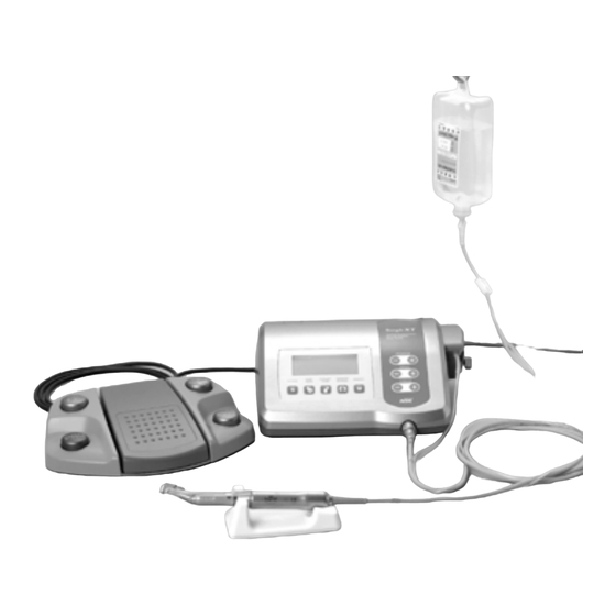
Микроэлектромотор Surgic XT от бренда «NSK» |
||||||
|
||||||
|
||||||
|
||||||
|
||||||
|
||||||
|
||||||
|
||||||
|
||||||
|
||||||
|
||||||
|
||||||
|
||||||
|


|
|
| Статистика Форума | |||
| Последние обновления тем: | Новые файлы хранилища: | Новые участники: | Top10 участников: |
An electronic circuit breaker automatically functions to protect the motor and the Control Unit if the motor is ever
overloaded. Power supply to the motor will automatically be terminated an Error code will be displayed on the Control
Unit.
When torque exceeds the set figures, «SAFE» will appear on the LCD, and the device will stop.
*Resetting the Protection Circuit
To reset the Protection Circuit, release and then depress the Speed Control Pedal.
8. Error Code & Troubleshooting
If an operational problem occurs the display will show an Error Code allowing immediate problem diagnosis.
When an error occurs, there will be a beep and an Error Code will appear on the LCD. The Error Code will blink until
the error is alleviated. The USB REC LCD will go on for about 10 seconds.
Error code
Error Mode
E0
System Error.
Excessive Current
E1
Detected.
Excessive Voltage
E2
Detected.
E3
Motor Sensor Error.
Control Unit Interior
E4
Over-heating Error.
E5
Breaking Error.
Motor Rotation
E6
Failure Error.
Cause of Error
Memory failure.
((Surgic Pro + ))
— Erroneous memory. (Not
USB)
— USB flash drive other
than the type stipulated
(mouse, printer, etc,) is
connected.
Extended use under heavy load.
Short circuit in the motor.
Motor cord failure.
Motor sensor failure (Hall IC).
Motor Cord failure.
Ingress of water into a Motor.
Overheating by extended use under
heavy load.
Operation of the Control Unit under
an extremely high temperature.
Abnormal voltage generated in the
start / stop switch circuit.
Failure in the start / stop switches
circuit.
Handpiece attachment failure.
Motor failure.
16
Remedy
Request repair.
Electrical contact may be insufficient.
Securely re-connect the Motor Cord.
When an error cannot be eliminated, request
repair.
Request repair.
Make sure to put a Protection Plug when
Thermo-disinfecting it.
Allow it to cool down before use.
Since heat is sufficiently radiated, periphery of
the main Control Unit should be
well-ventilated wherever possible. When an
error cannot be eliminated, request repair.
When rotation and stop are repeated in
short frequencies, a circuit may be activated
which limits acceleration at start. Wait a few
seconds and then use.
When an error cannot be eliminated, request
repair.
The chuck may be opened, or may not be
sufficiently closed. Securely close the chuck.
When an error cannot be eliminated, request
repair.
-
Contents
-
Table of Contents
-
Bookmarks
Quick Links
SURGERY SYSTEM
OPERATION MANUAL
0 1 9 7
OM-E0262E
Related Manuals for NSK Surgic XT
Summary of Contents for NSK Surgic XT
-
Page 1
SURGERY SYSTEM OPERATION MANUAL 0 1 9 7 OM-E0262E… -
Page 2: Table Of Contents
• Degree of protection against ingress of water as detailed in the current edition of IEC 529 : • Surgic XT is intended for use in dental, oral surgical, and surgical procedures. Do not use – Foot Control : IPX8 (Protected against the effects of continuous immersion in water) in operating rooms due to potential flammable gas mixtures present in such environment.
-
Page 3: Package Contents
Package contents Control Unit with an Irrigation Pump Irrigation Pump Program key Speed key Torque key Fuse Holder Micromotor Cord Jack Main Power Switch AC Electrical Cord Connection Jack Coolant Flow key Memory key Coolant Solution Hanger Post Gear Ratio key Foot Control Cord Jack Forward/Reverse key System key…
-
Page 4: Foot Control
Foot control S LCD display on the unit console Program Number Gear Ratio Foot Control Forward/Reverse cord and plug Speed/Torque Coolant solution flow Speed/Torque button volume button Coolant flow level Speed/Torque Bar Graph PRG (Program) button Forward/Reverse a Coolant Flow button Displays the selected coolant solution flow volume level.
-
Page 5: Installation
5-4 Installing the Irrigation Tube Installation Mount the irrigation tube in the irrigation pump, with the irrigation tube needle toward backside of the unit. Position the stoppers of the tube in the guide Position Tube Guide securely. (Fig.6) Position CAUTION lrrigation Tube Needle End Make sure that the tube is securely set on…
-
Page 6: Operation
5-6 Insertion of the irrigation tube Operation a Place the coolant solution bottle on the hanger post Bottle Cap 6-1 Programming the micromotor operation and insert the irrigation tube needle into the bottle cap. (Fig.11) lrrigation The control unit can memorize 10 sets of programs. Each program includes the following Tube Needle functions which will be automatically performed when the appropriate program number is selected.
-
Page 7: Care And Maintenance
To reverse direction of the micromotor (and bur) simply step on the foot control Forward / gears, and so on. The Surgic XT unit incorporates an automatic function to recognize the level Reverse button. A warning beep can be heard when the rotational direction is in reverse mode.
-
Page 8: Sterilization
7-3 Replacement of the fuse Sterilization Fuse box If the control unit does not function, check the fuses. To access the fuse box simply squeeze the fuse box The following items are autoclavable. lock located on the side of the control unit (Fig.18). If •…
-
Page 9: Optional Accessories
C202-750 Tube Clamp Supplied as standard accessory items. Y900-083 Tube Holder Supplied as standard accessory items. Z017-100 Spray lubricant Supplied as standard accessory items. NSK Surgical Handpieces Bur Speed Part No. Model No. Description Min. Max. C293 SGM-I Mini latch head –…
Перевести эту страницу
|
Микроэлектромотор Surgic XT от бренда «NSK» |
||||||
|
||||||
|
||||||
|
||||||
|
||||||
|
||||||
|
||||||
|
||||||
|
||||||
|
||||||
|
||||||
|
||||||
|
||||||
|
|
|
| Статистика Форума | |||
| Последние обновления тем: | Новые файлы хранилища: | Новые участники: | Top10 участников: |
An electronic circuit breaker automatically functions to protect the motor and the Control Unit if the motor is ever
overloaded. Power supply to the motor will automatically be terminated an Error code will be displayed on the Control
Unit.
When torque exceeds the set figures, «SAFE» will appear on the LCD, and the device will stop.
*Resetting the Protection Circuit
To reset the Protection Circuit, release and then depress the Speed Control Pedal.
8. Error Code & Troubleshooting
If an operational problem occurs the display will show an Error Code allowing immediate problem diagnosis.
When an error occurs, there will be a beep and an Error Code will appear on the LCD. The Error Code will blink until
the error is alleviated. The USB REC LCD will go on for about 10 seconds.
Error code
Error Mode
E0
System Error.
Excessive Current
E1
Detected.
Excessive Voltage
E2
Detected.
E3
Motor Sensor Error.
Control Unit Interior
E4
Over-heating Error.
E5
Breaking Error.
Motor Rotation
E6
Failure Error.
Cause of Error
Memory failure.
((Surgic Pro + ))
— Erroneous memory. (Not
USB)
— USB flash drive other
than the type stipulated
(mouse, printer, etc,) is
connected.
Extended use under heavy load.
Short circuit in the motor.
Motor cord failure.
Motor sensor failure (Hall IC).
Motor Cord failure.
Ingress of water into a Motor.
Overheating by extended use under
heavy load.
Operation of the Control Unit under
an extremely high temperature.
Abnormal voltage generated in the
start / stop switch circuit.
Failure in the start / stop switches
circuit.
Handpiece attachment failure.
Motor failure.
16
Remedy
Request repair.
Electrical contact may be insufficient.
Securely re-connect the Motor Cord.
When an error cannot be eliminated, request
repair.
Request repair.
Make sure to put a Protection Plug when
Thermo-disinfecting it.
Allow it to cool down before use.
Since heat is sufficiently radiated, periphery of
the main Control Unit should be
well-ventilated wherever possible. When an
error cannot be eliminated, request repair.
When rotation and stop are repeated in
short frequencies, a circuit may be activated
which limits acceleration at start. Wait a few
seconds and then use.
When an error cannot be eliminated, request
repair.
The chuck may be opened, or may not be
sufficiently closed. Securely close the chuck.
When an error cannot be eliminated, request
repair.
-
Contents
-
Table of Contents
-
Bookmarks
Quick Links
SURGERY SYSTEM
OPERATION MANUAL
0 1 9 7
OM-E0262E
Related Manuals for NSK Surgic XT
Summary of Contents for NSK Surgic XT
-
Page 1
SURGERY SYSTEM OPERATION MANUAL 0 1 9 7 OM-E0262E… -
Page 2: Table Of Contents
• Degree of protection against ingress of water as detailed in the current edition of IEC 529 : • Surgic XT is intended for use in dental, oral surgical, and surgical procedures. Do not use – Foot Control : IPX8 (Protected against the effects of continuous immersion in water) in operating rooms due to potential flammable gas mixtures present in such environment.
-
Page 3: Package Contents
Package contents Control Unit with an Irrigation Pump Irrigation Pump Program key Speed key Torque key Fuse Holder Micromotor Cord Jack Main Power Switch AC Electrical Cord Connection Jack Coolant Flow key Memory key Coolant Solution Hanger Post Gear Ratio key Foot Control Cord Jack Forward/Reverse key System key…
-
Page 4: Foot Control
Foot control S LCD display on the unit console Program Number Gear Ratio Foot Control Forward/Reverse cord and plug Speed/Torque Coolant solution flow Speed/Torque button volume button Coolant flow level Speed/Torque Bar Graph PRG (Program) button Forward/Reverse a Coolant Flow button Displays the selected coolant solution flow volume level.
-
Page 5: Installation
5-4 Installing the Irrigation Tube Installation Mount the irrigation tube in the irrigation pump, with the irrigation tube needle toward backside of the unit. Position the stoppers of the tube in the guide Position Tube Guide securely. (Fig.6) Position CAUTION lrrigation Tube Needle End Make sure that the tube is securely set on…
-
Page 6: Operation
5-6 Insertion of the irrigation tube Operation a Place the coolant solution bottle on the hanger post Bottle Cap 6-1 Programming the micromotor operation and insert the irrigation tube needle into the bottle cap. (Fig.11) lrrigation The control unit can memorize 10 sets of programs. Each program includes the following Tube Needle functions which will be automatically performed when the appropriate program number is selected.
-
Page 7: Care And Maintenance
To reverse direction of the micromotor (and bur) simply step on the foot control Forward / gears, and so on. The Surgic XT unit incorporates an automatic function to recognize the level Reverse button. A warning beep can be heard when the rotational direction is in reverse mode.
-
Page 8: Sterilization
7-3 Replacement of the fuse Sterilization Fuse box If the control unit does not function, check the fuses. To access the fuse box simply squeeze the fuse box The following items are autoclavable. lock located on the side of the control unit (Fig.18). If •…
-
Page 9: Optional Accessories
C202-750 Tube Clamp Supplied as standard accessory items. Y900-083 Tube Holder Supplied as standard accessory items. Z017-100 Spray lubricant Supplied as standard accessory items. NSK Surgical Handpieces Bur Speed Part No. Model No. Description Min. Max. C293 SGM-I Mini latch head –…