
-
Page 1
Service Manual Controller SIGMA CONTROL 2 BLOWER ≥ 2.5.3 No.: 901700 10 E Manufacturer: KAESER KOMPRESSOREN SE 96410 Coburg • PO Box 2143 • GERMANY • Tel. +49-(0)9561-6400 • Fax +49-(0)9561-640130 www.kaeser.com… -
Page 2
/KKW/SSC 2.11 en IBA-SIGMA CONTROL BLOWER /KKW/SSC 2.11 20200824 081558… -
Page 3: Table Of Contents
Contents SIGMA CONTROL 2 Quick installation guide Operating elements ………………….Display elements ………………….Main menu – Overview ………………… Functions – Overview ………………….. Regarding this document Using this document ………………….Copyright …………………….. 2.2.1 Software ………………….Certification ……………………Updating the operating manual ………………
-
Page 4
Pressure control ………………..8.6.5 External speed definition ………………8.6.6 Control with external variable …………….8.6.7 SFC acceleration time ………………Setting the machine for master control operation …………Service Manual Controller SIGMA CONTROL 2 BLOWER ≥ 2.5.3 No.: 901700 10 E… -
Page 5
Spares, Operating Materials, Service 12.1 Note the nameplate ………………….170 12.2 KAESER AIR SERVICE ………………..170 12.3 Displaying the version number, machine model, material number and serial number ..170 Service Manual Controller No.: 901700 10 E SIGMA CONTROL 2 BLOWER ≥ 2.5.3… -
Page 6
13.2 Packing ……………………..13.3 Storage ……………………..173 13.4 Transporting ……………………173 13.5 Battery removal and disposal ………………. 173 13.5.1 Battery disposal in accordance with local environmental regulations….173 Service Manual Controller SIGMA CONTROL 2 BLOWER ≥ 2.5.3 No.: 901700 10 E… -
Page 7
Backup menu ……………………..Fig. 29 Data recording menu ……………………Fig. 30 Fig. 31 Direct connection of two SIGMA CONTROL 2 …………….116 Fig. 32 Operating mode …………………….. 133 Fig. 33 Switching the compressed air station on and off ……………. 134 Fig. -
Page 8
List of Illustrations Service Manual Controller SIGMA CONTROL 2 BLOWER ≥ 2.5.3 No.: 901700 10 E… -
Page 9
Assignment of the Modbus TCP interface ……………… Tab. 25 Recommended conductors — Modbus TCP interface …………..Tab. 26 Technical specifications — SIGMA CONTROL 2 communication module ……..Tab. 27 Assignment of the SIGMA CONTROL 2 interface …………..Tab. 28 Technical Specifications — SIGMA CONTROL 2 interface ………… -
Page 10
Fault displays in the Communication – Com-Module menu…………166 Tab. 107 Com-Module communication error warning message …………..167 Tab. 108 Fault displays in the Communication – Com-Module menu…………167 Service Manual Controller viii SIGMA CONTROL 2 BLOWER ≥ 2.5.3 No.: 901700 10 E… -
Page 11: Sigma Control 2 Quick Installation Guide
SIGMA CONTROL 2 Quick installation guide Operating elements 1 SIGMA CONTROL 2 Quick installation guide Operating elements Fig. 1 Operating elements Item Designation Function «Up» Scrolls up the menu options. Increases a parameter value. «Left» Jumps to the left. Moves the cursor position to the left.
-
Page 12: Display Elements
SIGMA CONTROL 2 Quick installation guide Display elements Display elements Fig. 2 Display elements Item Designation Function Display illuminates green when the machine switched on. Display Graphic display with 8 lines and 30 characters per line. Time control Continuous green light when the machine is controlled by the timer.
-
Page 13: Functions — Overview
SIGMA CONTROL 2 Quick installation guide Functions – Overview Menu No. Menu name Function Performance data Displays measured data of the machine and its components (e.g., motors) Operating data Displays operating hours of the machine and its components Maintenance Displays maintenance data of the machine and its components…
-
Page 14: Tab. 4 Functions — Overview
SIGMA CONTROL 2 Quick installation guide Functions – Overview Function Menu Steps Chapter Activating the – Activate the «Remote» key – Press «Remote» key 8.2.13 «remote control» <Operating data – Operating hours – Motor / Block> Displaying oper‐ ating data Changing the op‐…
-
Page 15: Regarding This Document Using This Document
The licenses can be also found under these addresses: http://www.gnu.org/licenses http://code.google.com/p/curve25519-donna/ Within three years from receipt of SIGMA CONTROL 2, you may obtain the complete source code of the copyright-protected software packages by sending a corresponding order to the following ad‐ dress:…
-
Page 16: Certification
(for example: when connecting to computers or peripheral equipment use shielded cables on‐ ly). Updating the operating manual Go to our website http://www.kaeser.com/sc2manual to find the latest version of the operating manual. ➤ Download the desired operating manual from our server and forward it to your operators.
-
Page 17: Potential Damage Warnings
Potential effects when ignoring the warning are indicated here. ➤ The protective measures against the damages are shown here. ➤ Carefully read and fully comply with warnings against damages. Service Manual Controller No.: 901700 10 E SIGMA CONTROL 2 BLOWER ≥ 2.5.3…
-
Page 18: Other Alert Notes And Their Symbols
➤ … as is a solution. This symbol identifies important information or measures regarding the protection of the envi‐ ronment. Further information Further subjects are introduced here. Service Manual Controller SIGMA CONTROL 2 BLOWER ≥ 2.5.3 No.: 901700 10 E…
-
Page 19: Technical Specifications 3.1 Controller Sigma Control 2
255 x 128 Width [mm] Height [mm] Maximum number of lines/characters 8/30 Colours Black/white with grey scale Lighting LED backlit px ≙ pixel Tab. 9 Display data Service Manual Controller No.: 901700 10 E SIGMA CONTROL 2 BLOWER ≥ 2.5.3…
-
Page 20: Fig. 3 Mcs Interfaces
The positions of the interfaces X1–X6 are marked on the rear of the controller. Tab. 10 MCS interfaces Identification with RFID Equipment Card Characteristic Value Hardware on the SIGMA CONTROL 2 controller RFID reader Hardware (external) RFID Equipment Card Recognition distance [m] Max. 0.05 Frequency [MHz] 13.56…
-
Page 21: Input/Output Module
Power is provided by the power supply unit within the machine. Characteristic Value Rated voltage (stabilised) [V DC] Current consump‐ tion SIGMA CONTROL 2 with IOM 1 [A] IOM ≙ Input/Output module Tab. 13 Power supply specifications 3.1.2.2 Maximum cable lengths…
-
Page 22: Sensors
Value Sensing resistance (to DIN IEC 751) PT100 Connection Two-core Tab. 18 Resistance thermometer Communication modules SIGMA CONTROL 2 supports the following communication modules: ■ PROFIBUS (Option C41) ■ Modbus (Option C42) ■ DeviceNet (Option C43) ■ Modbus TCP (Option C44) ■…
-
Page 23: Profibus Module
Value Controller SIGMA CONTROL 2 SIGMA AIR MANAGER 4.0 SIGMA CONTROL 2 or ASCII, RS485 or RS232, galvanically isolated Baud rate Adjustable, possible baud rates: [bps] 1200 / 2400 / 4800 / 9600 / 19200 / 38400 / 57600 / 76800 / 115200…
-
Page 24: Modbus Tcp Module
7_9696_PA. Bold elements: Factory setting Tab. 21 Technical Specifications — SIGMA CONTROL 2 interface Assignment of the SIGMA CONTROL 2 interface The Modbus interface is galvanically isolated and features RS485 and RS2232 signals. To use the RS232 interface, connect Pin 2 with Pin 3.
-
Page 25: Devicenet Module
Baud rate [kbps] Automatic recognition, possible baud rates: 125–500 Input data [byte] Output data [byte] 128 Data content «Technical description SIGMA CONTROL 2 process image», document number 7_7601xPA. Tab. 26 Technical specifications — SIGMA CONTROL 2 communication module Service Manual Controller No.: 901700 10 E…
-
Page 26: Profinet Module
Feature Value Controller SIGMA CONTROL 2 SIGMA AIR MANAGER 4.0 SIGMA CONTROL 2 device (Slave) with RT classification, conformity class B, topology detection (LLDP), network management (SNMP), redundancy, MRP protocol Connection 2x RJ45 ports (Cat5e), 2-port switch, potential isolation Baud…
-
Page 27: Ethernet/Ip-Module
Housing Cable shield — High-impedance (1 MOhm/47 nF) connection with func‐ tional earthing (FE) * Position of pins 1 through 8, see chapter 9 Tab. 29 Assignment of the SIGMA CONTROL 2 interface Recommended conduit Feature Value Conductor PROFINET conductor, CAT5 shielded, CU, for example: 7.7629.0 Plug Bus plug RJ45, IP20, for example: 7.7628.0 or 7.7628.1…
-
Page 28: Tab. 32 Configuration Of The Ethernet/Ip-Interface
Conductor Network conductor, CAT5 shielded, CU, for example: 7.7629.0 Plug Bus plug RJ45, IP20, for example: 7.7628.1 Maximum cable length [m] Tab. 33 EtherNet/IP-Interface — Cabling recommendation Service Manual Controller SIGMA CONTROL 2 BLOWER ≥ 2.5.3 No.: 901700 10 E…
-
Page 29: Safety And Responsibility Basic Instructions
The safety regulations of the machine in which SIGMA CONTROL 2 is installed apply. Specified use SIGMA CONTROL 2 is solely intended for the control of machines in which SIGMA CONTROL 2 is factory-installed. Any other use is considered incorrect. The manufacturer is not liable for any dam‐…
-
Page 30: Design And Function
All other sections apply to both machine types. The controller SIGMA CONTROL 2 controls, regulates, monitors, and protects the machine. All parameters needed to operate KAESER blowers can be set and displayed using the controller. Various user-dependent password mechanisms protect the parameters. Components SIGMA CONTROL 2 has the following components: ■…
-
Page 31: Fig. 4 System Structure
SIGMA CONTROL 2. The protective function allows: ■ Automatic machine shutdown on alarms that may lead to damage to the machine, e.g. overcur‐ rent, overpressure, overtemperature. Service Manual Controller No.: 901700 10 E SIGMA CONTROL 2 BLOWER ≥ 2.5.3…
-
Page 32: Operating Panel
«Information» Displays the event memory. «Acknowledgement» Confirms/acknowledges alarms and warning messages. If permissible: Resets the fault counter (RESET). not for SXC Tab. 34 Operating elements Service Manual Controller SIGMA CONTROL 2 BLOWER ≥ 2.5.3 No.: 901700 10 E…
-
Page 33: Display Elements
RFID is the abbreviation for “Radio Frequency Identification” and makes possible to identify per‐ sons and objects. Placing a suitable transponder in front of the RFID reader of the controller will automatically acti‐ vate the communication between transponder and SIGMA CONTROL 2. Service Manual Controller No.: 901700 10 E…
-
Page 34: Display
Press «Enter» or one of the arrow keys to open the main menu. Here, you can set the language to be used for the display of texts or open the various submenus. Service Manual Controller SIGMA CONTROL 2 BLOWER ≥ 2.5.3 No.: 901700 10 E…
-
Page 35: Operating Mode
The following parameters with their current values are displayed in line 8: ■ The hours during which the machine was activated ■ Remaining desiccant service life of the machine until the next maintenance. Service Manual Controller No.: 901700 10 E SIGMA CONTROL 2 BLOWER ≥ 2.5.3…
-
Page 36: Main Menu
The «Enter» key affects only the active line. In some lines, you can change more than one parameter. In this case, you must first select the specific parameter with the «Left» or «Right» keys. Service Manual Controller SIGMA CONTROL 2 BLOWER ≥ 2.5.3 No.: 901700 10 E…
-
Page 37: Activating Keys With Check Boxes
5.4.4 Activating keys with check boxes Certain keys of the SIGMA CONTROL 2 are locked by default. Activate the corresponding check boxes in the active line of the display to unlock these keys. First, press «Enter» to switch into setting mode. The check box will flash.
-
Page 38: Kaeser Connect
If you lose both RFID Equipment Cards, you can register a new RFID Equipment Card only after having entered the user name and the password. A new RFID Equipment Card may be registered by the KAESER Service subject to a fee, if the user name and the password are lost. KAESER CONNECT Using an Internet-capable device with web browser, you can open a visualisation of the controller.
-
Page 39: Menu Overview
■ Date display format ■ Time display format Backup Saving data via KAESER CONNECT from SIGMA CONTROL 2 to a PC not for SXC Tab. 39 KAESER CONNECT functions Further information For opening KAESER CONNECT, login and other procedures, please see chapter 8.3.
-
Page 40: Menu Structure
Statistics ■ DI/DO display ■ Current operating mode Status menu, please see ta‐ For details of the ble 41. Power switching with frequency converter (OFC/SFC) Screw blower Service Manual Controller SIGMA CONTROL 2 BLOWER ≥ 2.5.3 No.: 901700 10 E…
-
Page 41
Filter transmission venting Electrical equipment Annual maintenance due on Configuration menu, please 5 Configuration For details of the see table 42. Power switching with frequency converter (OFC/SFC) Screw blower Service Manual Controller No.: 901700 10 E SIGMA CONTROL 2 BLOWER ≥ 2.5.3… -
Page 42
Block ■ Sound enclosure cooling ■ AFxM-valve ■ Aftercooler Components menu, please For details of the see table 45. Power switching with frequency converter (OFC/SFC) Screw blower Service Manual Controller SIGMA CONTROL 2 BLOWER ≥ 2.5.3 No.: 901700 10 E… -
Page 43: Tab. 40 Menu Structure Of Main Menu
Motor starts total since/Reset Motor starts /h Motor starts /d 1.3 DI/DO display 1st I/O module DI/DO display only visible in the event of parametrisation error Service Manual Controller No.: 901700 10 E SIGMA CONTROL 2 BLOWER ≥ 2.5.3…
-
Page 44: Tab. 41 Status Menu
Date/Time Time zone ■ Time server ─ active: ─ IP address Date format Time format Pressure unit Temperature unit Display illumination Power switching with frequency converter (OFC/SFC) Service Manual Controller SIGMA CONTROL 2 BLOWER ≥ 2.5.3 No.: 901700 10 E…
-
Page 45
Load control Load on/Load off Load on/Load off ─ xA/xB Clock xA/xB RC dt maintenance hours Ramp up time Ramp down time: Power switching with frequency converter (OFC/SFC) Service Manual Controller No.: 901700 10 E SIGMA CONTROL 2 BLOWER ≥ 2.5.3… -
Page 46: Tab. 42 Configuration Menu
External message 2 ─ External message 3 ■ Switch ─ ─ ─ ─ ─ ─ ─ block speed Power switching with frequency converter (OFC/SFC) Configuration menu Tab. 42 Service Manual Controller SIGMA CONTROL 2 BLOWER ≥ 2.5.3 No.: 901700 10 E…
-
Page 47: Tab. 43 Communication Menu
The following KAESER communications mod‐ ules may be used: ■ PROFIBUS ■ Modbus ■ Modbus TCP ■ DeviceNet ■ PROFINET ■ EtherNet/IP Communication menu Tab. 43 Service Manual Controller No.: 901700 10 E SIGMA CONTROL 2 BLOWER ≥ 2.5.3…
-
Page 48: Tab. 44 Connections Menu
─ SAM 4.0 active: Send/Receive Send ─ IP address ─ Port ─ Communication error Start td Timeout Load signal Restart Timeout Cycle time Connections menu Tab. 44 Service Manual Controller SIGMA CONTROL 2 BLOWER ≥ 2.5.3 No.: 901700 10 E…
-
Page 49
Motor temperature ─ Collection ─ ■ Greasing system ─ ─ ─ Interval ─ Target/Actual ─ Alarm ─ td/Actual Motor type Power switching with frequency converter (OFC/SFC) Screw blower Service Manual Controller No.: 901700 10 E SIGMA CONTROL 2 BLOWER ≥ 2.5.3… -
Page 50
─ ─ ─ ─ n_ref, p ■ Speed monitoring ■ Vibration monitoring ─ VSE Status ─ ─ ↑ V1 Power switching with frequency converter (OFC/SFC) Screw blower Service Manual Controller SIGMA CONTROL 2 BLOWER ≥ 2.5.3 No.: 901700 10 E… -
Page 51: Control Modes
Screw blower Components menu Tab. 45 Control modes The behaviour of machines with SIGMA CONTROL 2 is determined by three software control modes interacting with each other. 5.8.1 Ready control mode The ready control mode specifies whether individual machines or machines under master control can be activated.
-
Page 52: Operating Control
Tab. 46 SIGMA CONTROL 2 ready states When the operating voltage is applied to the SIGMA CONTROL 2 controller, the operating control is in OFF mode. If all faults are inactive, pressing «ON» produces the ON ready mode. If remote control is active, the remote load demand and remote idle demand signals are evaluated.
-
Page 53
IDLE The air generated by the compressor is vented into the atmosphere. The drive motor runs unloaded and consumes very little power. IDLE LED lights green. ■ Service Manual Controller No.: 901700 10 E SIGMA CONTROL 2 BLOWER ≥ 2.5.3… -
Page 54
5.8.2.1 Operating control without load/idle valve When the operating voltage is applied to SIGMA CONTROL 2, the operation control is in STOP operating mode and then switches to READY mode. Triggered by the Load run command, the drive motor starts via the MOTOR START operating mode and switches to LOAD operating mode. -
Page 55
The Stop command or the end of the shut-down switches the control to the STOP state. Service Manual Controller No.: 901700 10 E SIGMA CONTROL 2 BLOWER ≥ 2.5.3… -
Page 56: Installation And Operating Conditions
Direct sunlight (UV radiation) can destroy the display screen. ➤ Do not allow the display screen to be subjected to direct sunlight. ➤ See the machine’s operating manual for required conditions. Service Manual Controller SIGMA CONTROL 2 BLOWER ≥ 2.5.3 No.: 901700 10 E…
-
Page 57: Installation
Time control: Risk of injury caused by unexpected starting! ➤ Make sure the power supply disconnecting device is switched off before commencing any work on the machine. Tab. 49 Machine identification Service Manual Controller No.: 901700 10 E SIGMA CONTROL 2 BLOWER ≥ 2.5.3…
-
Page 58: Initial Start-Up Outline
8 Initial Start-up Outline SIGMA CONTROL 2 was designed and developed for a number of applications. The settings that can be made are correspondingly varied. It is possible that only a few of these settings are needed for the initial start-up. This depends on the application.
-
Page 59: Selecting Menu Options
All menu options can be selected with the «Down», «Up» and «Enter» keys. Example: Select the < Configuration – General > menu option 1. Switch on the machine and wait for SIGMA CONTROL 2 to start. The operating mode is displayed.
-
Page 60: Setting The Language
Main menu Active line with current set language —————-English GB—————- Sub-menu ▶1 Status Sub-menu ▶2 Performance data Sub-menu ▶3 Operating data Sub-menu ▶4 Maintenance Sub-menu ▶5 Configuration Service Manual Controller SIGMA CONTROL 2 BLOWER ≥ 2.5.3 No.: 901700 10 E…
-
Page 61: Noting The User Name
8.2.4 User log-on with RFID Equipment Card The RFID Equipment Card enables you to easily and quickly log on at SIGMA CONTROL 2. It au‐ thorises you to access advanced functions of the controller. Advanced access rights allow you to: ■…
-
Page 62: Generating A Password
In the event that your RFID Equipment Card is damaged or lost, you must manually log on to SIGMA CONTROL 2. A password is also required to use KAESER CONNECT to log on at SIGMA CONTROL 2 (see chapter 8.3).
-
Page 63: Manual User Log-On
2. Use «Up» or «Down» to select the 3. Press «Enter». The setting mode is active. A column with alphanumeric characters is displayed. The selected character flashes. Service Manual Controller No.: 901700 10 E SIGMA CONTROL 2 BLOWER ≥ 2.5.3…
-
Page 64: Create The Master Rfid Equipment Card
11. Use «Up» or «Down» to select the 12. Press «Enter». Current access level 2 is displayed. Result You are now logged on to SIGMA CONTROL 2 with access level 2, having manually input your user name and the password. 8.2.7 Create the master RFID Equipment Card If you are running several KAESER machines with the SIGMA CONTROL 2 control it may make sense to create a master RFID Equipment Card with which you can log onto all machines.
-
Page 65: Checking/Setting Time And Date
See chapter 8.2.16. <Configuration – General> menu. 1. Open the 5.1 Date/Time line. 2. Use «Up» or «Down» to select the Service Manual Controller No.: 901700 10 E SIGMA CONTROL 2 BLOWER ≥ 2.5.3…
-
Page 66
4. Press «Enter». 00.00.00 flashes. The display for days 5. Use «Up» or «Down» to set the day. 6. Press the «Right» arrow. 00.00.00 flashes. The display for months Service Manual Controller SIGMA CONTROL 2 BLOWER ≥ 2.5.3 No.: 901700 10 E… -
Page 67: Set The Time Zone
11. Press «Escape» repeatedly to leave this menu. 8.2.9 Set the time zone Set the time zone for the SIGMA CONTROL 2 to ensure the timely automatic conversion from win‐ ter time (standard time) to daylight savings time, for example. Precondition Access level 2 is activated.
-
Page 68: Tab. 52 Possible Settings For The Time Format
8 0 ° C Menu 5.1 General Europe/London ······························ ▶2 Time server ······························ Date format MM/DD/YY time format Time format hh:mm:ssAM/PM 3. Press «Enter». hh:mm:ssAM/PM indication flashes. Service Manual Controller SIGMA CONTROL 2 BLOWER ≥ 2.5.3 No.: 901700 10 E…
-
Page 69: Tab. 53 Possible Settings For The Pressure Unit
The setting is applied. 6. Press «Escape» repeatedly to leave this menu. Setting the temperature display units Set the temperature unit for display: Format Example °C 46°C 319K Service Manual Controller No.: 901700 10 E SIGMA CONTROL 2 BLOWER ≥ 2.5.3…
-
Page 70: Setting The Display Illumination
Display illumination Precondition Access level 2 is activated. <Configuration – General> menu. 1. Open the 5.1 2. Use «Up» or «Down» to select the Display illumination line. Service Manual Controller SIGMA CONTROL 2 BLOWER ≥ 2.5.3 No.: 901700 10 E…
-
Page 71: Setting The Contrast And The Brightness
Contrast and brightness are set. 8.2.13 Activating the remote control The «remote control» key on the operating panel of the SIGMA CONTROL 2 can be activated or deactivated. Various menus offer check boxes for this setting. Precondition Access level 2 is activated.
-
Page 72: Ip Configuration
8.2.14 IP configuration For the SIGMA CONTROL 2 to be connected to the network, you must set the IP configuration (for KAESER CONNECT for example). If you use SIGMA CONTROL 2 as the master control of two machines, you set other network IP configuration menu (see chapter 8.7.4).
-
Page 73: Tab. 56 Network Parameters
Example address DNS Server 1 008.008.008.008 Example address DNS Server 2 008.008.004.004 Active line Restart network ☐ 12. Press «Enter». The check box Restart network will flash. Service Manual Controller No.: 901700 10 E SIGMA CONTROL 2 BLOWER ≥ 2.5.3…
-
Page 74: Setting The E-Mail Function
The network is restarted. The set network parameters are active. 8.2.15 Setting the e-mail function SIGMA CONTROL 2 is able to send messages via e-mail. For this purpose, a network connection with an SMTP server is required. Setting e-mail parameters Precondition Access level 2 is activated.
-
Page 75
Setting the controller 6. Set the e-mail parameters as described above: If SIGMA CONTROL 2 is connected via SIGMA NETWORK to SAM 4.0 and emails are to be SMTP forwarded via SAM 4.0, then enter the IP address of interface X6 of SAM 4.0 in the server: field. -
Page 76: Setting The Time Server
8.2.16 Setting the time server If SIGMA CONTROL 2 is connected to the network, you can set the access to an SNTP server available in the Internet or a local Intranet. SIGMA CONTROL 2 then automatically imports the date and time settings and ensures continuous synchronisation of the internal clock with the exter‐…
-
Page 77: Kaeser Connect Benefits
Settings ■ Backup ■ Data recording Thus, KAESER CONNECT provides an excellent option for an easy and quick check of the econo‐ my and energy efficiency of your machines. Service Manual Controller No.: 901700 10 E SIGMA CONTROL 2 BLOWER ≥ 2.5.3…
-
Page 78: Open Kaeser Connect
The user name (see chapter 8.2.3) and password (see chapter 8.2.5) are known. The controller’s IP address is known, see chapters 8.2.14 and 8.7.4. 1. Use an Ethernet cable to connect SIGMA CONTROL 2 to the Internet-capable device or net‐ work.
-
Page 79: System Status Menu
7. Click to set the selected language Result KAESER CONNECT is displayed in the set language. 8.3.2 System status menu Precondition KAESER CONNECT for SIGMA CONTROL 2 is displayed. Service Manual Controller No.: 901700 10 E SIGMA CONTROL 2 BLOWER ≥ 2.5.3…
-
Page 80: Fig. 19 System Status Menu
Initial Start-up KAESER CONNECT benefits System status menu Fig. 19 System status menu element. 1. Click the System status menu is displayed Fig. 20 Main menu Service Manual Controller SIGMA CONTROL 2 BLOWER ≥ 2.5.3 No.: 901700 10 E…
-
Page 81: Graphs Menu
Initial Start-up KAESER CONNECT benefits 2. Click in the SIGMA CONTROL 2 display. The Main menu is displayed. 3. Click the numbered lines. The system displays the corresponding sub-menus. 4. Press ESC repeatedly to leave this menu. 8.3.3 Graphs menu…
-
Page 82: Fig. 22 Control Keys
An SD card with sufficient free memory is inserted in the X5 SD card slot The SD card was inserted for the entire operating time of the machine. The SIGMA CONTROL 2 data recorder function is activated. Start: . 1. Enter the date and time for the start time in the required time period in End: .
-
Page 83: Messages Menu
■ Blower messages ■ System messages ■ Diagnostic messages Precondition KAESER CONNECT for SIGMA CONTROL 2 is displayed. Messages (illustration similar) Fig. 23 Messages menu element. 1. Click the Messages menu is displayed 2. Click the required message type. 3. Check messages.
-
Page 84: User Management Menu
User name: 6 to 16 characters, the second character must not be a number ■ Password: 6 to 16 characters Precondition The generated password is available. KAESER CONNECT for SIGMA CONTROL 2 is displayed. Service Manual Controller SIGMA CONTROL 2 BLOWER ≥ 2.5.3 No.: 901700 10 E…
-
Page 85: Fig. 25 User Management Menu
Log on for write access: window User name: field. 3. Enter your user name in the Password: field. 4. Enter your password in the 5. Click OK. User management menu is displayed Service Manual Controller No.: 901700 10 E SIGMA CONTROL 2 BLOWER ≥ 2.5.3…
-
Page 86: Fig. 27 User Management Menu
1. Click the required user account in the list. Password: field. 2. Enter a new password in the Repeat password: field. 3. Re-enter the same new password in the 4. Click Update user. Service Manual Controller SIGMA CONTROL 2 BLOWER ≥ 2.5.3 No.: 901700 10 E…
-
Page 87: Settings Menu
Initial Start-up KAESER CONNECT benefits Result The password for the existing user account is changed. 8.3.7 Settings menu These settings are only required for access to KAESER CONNECT via web browser. The following settings are possible. ■ Units ■ Date format ■…
-
Page 88: Save Data Menu
Initial Start-up KAESER CONNECT benefits 8.3.8 Save data menu Backup menu allows you to download data from SIGMA CONTROL 2 to the Internet-capable device. The following backup types are available: ■ Backup all ■ Log files ■ Settings ■ User information Precondition KAESER CONNECT for SIGMA CONTROL 2 is displayed.
-
Page 89: Kaeser Connect Exit
The downloaded data can be sent to KAESER SERVICE for evaluation and service support. 8.3.10 KAESER CONNECT exit In order to close KAESER CONNECTfor SIGMA CONTROL 2, click Logout in the header. ➤ Click Logout. Result The system displays a message confirming the successful logout.
-
Page 90: Displaying And Setting The Blower Properties
The installation elevation can be set within certain limits: Precondition Access level 2 is activated. 1. Open the 5.2 <Configuration – Blower properties> menu. Altitude line. 2. Use «Up» or «Down» to select the Service Manual Controller SIGMA CONTROL 2 BLOWER ≥ 2.5.3 No.: 901700 10 E…
-
Page 91: Machine Start And Machine Stop
Automatic start/stop in timer mode Overview Time control ■ Select menu ■ Set clock program ■ Activating time control 8.5.1.1 Select the Time control menu Precondition Access level 2 is activated. Service Manual Controller No.: 901700 10 E SIGMA CONTROL 2 BLOWER ≥ 2.5.3…
-
Page 92: Tab. 61 User-Defined Clock Programme Machine On/Off
All current switching points are reset Reset ☐ ······························ Active line n.a. 00:00AM n.a. 00:00AM n.a. 00:00AM User-defined clock program No.: Time Function Tab. 61 User-defined clock programme machine ON/OFF Service Manual Controller SIGMA CONTROL 2 BLOWER ≥ 2.5.3 No.: 901700 10 E…
-
Page 93: Tab. 62 Example Of A Machine On/Off Clock Program
3. Press «Enter». n.a. indication flashes. 4. Use «Up» or «Down» to set the weekdays. 5. Press the «Enter» key. The setting is applied. 6. Press the «Right» key. Service Manual Controller No.: 901700 10 E SIGMA CONTROL 2 BLOWER ≥ 2.5.3…
-
Page 94
☐ ······························ Switching point 01: Mon-Fri 06:30AM Switching point 02 Mon-Fri 12:00PM Switching point 03 Mon-Fri 01:00PM 3. Press the «Up» key. The check box is activated. Service Manual Controller SIGMA CONTROL 2 BLOWER ≥ 2.5.3 No.: 901700 10 E… -
Page 95: Automatic Start/Stop With Timer
Precondition The «Time control» key is activated; see chapter 8.5.1.3. ➤ Press the «Time control» key on the SIGMA CONTROL 2 operating panel to activate the time control. Time control LED on the operating panel of the SIGMA CONTROL 2 signalises with green Result continuous light that the machine is operated with activated time control.
-
Page 96: Automatic Restart» Function
The first machine may start immediately and does not require a delay time. Machine number Start time [sec] Delay time [sec] –– –– Service Manual Controller SIGMA CONTROL 2 BLOWER ≥ 2.5.3 No.: 901700 10 E…
-
Page 97: Tab. 63 Delay Time For Automatic Restart
5. Press the «Enter» key. The setting is applied. Result You have adjusted the delay tome for the restart after a power supply failure from 1 s to 10 s. Service Manual Controller No.: 901700 10 E SIGMA CONTROL 2 BLOWER ≥ 2.5.3…
-
Page 98: Controlling Machine From A Remote Location
Activating the remote control On LED lights green. ■ Press the «ON »key. The Two methods are available to start the machine remotely from a control centre: Service Manual Controller SIGMA CONTROL 2 BLOWER ≥ 2.5.3 No.: 901700 10 E…
-
Page 99
The setting is applied. 7. Press the «Right» key. 8. Press «Enter». The check box assigned to the input flashes. 9. Press the «Up» key. The check box is activated. Service Manual Controller No.: 901700 10 E SIGMA CONTROL 2 BLOWER ≥ 2.5.3… -
Page 100
The setting is applied. 7. Press the «Right» key. 8. Press «Enter». The check box assigned to the input flashes. 9. Press the «Up» key. The check box is activated. Service Manual Controller SIGMA CONTROL 2 BLOWER ≥ 2.5.3 No.: 901700 10 E… -
Page 101: Operating Modes In Frequency-Controlled Machines
8.5.4.3 Activating the remote control ➤ Activate remote control see chapter 8.2.13. Result SIGMA CONTROL 2 remote control is activated. Operating modes in frequency-controlled machines Operating You can set various operating modes in frequency-controlled machines. Use the 5.4 modes menu for specifying the settings. The selection options for the operating modes depend on Current signal the configuration of the AII1.02 current signal.
-
Page 102: Current Signal Aii1.02
Precondition Access level 2 is activated. The operating mode is displayed. Fixed speed or Pressure control mode is set in the 5.4 <Configuration – Operating modes> menu. Service Manual Controller SIGMA CONTROL 2 BLOWER ≥ 2.5.3 No.: 901700 10 E…
-
Page 103: Setting The Operating Mode
The setting mode is active. The currently set language flashes. 4. Use «Up» or «Down» to set the required operating mode. 5. Press «Enter». The setting is applied. Service Manual Controller No.: 901700 10 E SIGMA CONTROL 2 BLOWER ≥ 2.5.3…
-
Page 104: Constant Speed
4. Press «Enter». The setting is applied. ▶1Fixed speed line. 5. Use «Up» or «Down» to select the 6. Press «Enter». Fixed speed menu is displayed. The 5.4.1 Service Manual Controller SIGMA CONTROL 2 BLOWER ≥ 2.5.3 No.: 901700 10 E…
-
Page 105: Pressure Control
Access level 2 is activated. <Configuration – Operating modes – Pressure control> menu. 1. Open the 5.4.2 2. Use «Up» or «Down» to select the Source actual pressure line. Service Manual Controller No.: 901700 10 E SIGMA CONTROL 2 BLOWER ≥ 2.5.3…
-
Page 106
Local set pressure 1.0bar 1.0rpm / mbar 1.00rpm / (mbar *s) Set pressure rise time Local set pressure . 4. Use «Up» or «Down» to set the value for Service Manual Controller SIGMA CONTROL 2 BLOWER ≥ 2.5.3 No.: 901700 10 E… -
Page 107
PI controller and is performed empirically. Precondition Access level 2 is activated. Starting value KP: 0.1 rpm / mbar Starting value KI: 0.01 rpm / (mbar *s) Service Manual Controller No.: 901700 10 E SIGMA CONTROL 2 BLOWER ≥ 2.5.3… -
Page 108: External Speed Definition
Current signal AII1.02 menu to set the scaling of the 4–20 mA signal. The galvanic Use the 5.5.1 decoupling of the signal is performed via a buffer amplifier installed in the control cabinet. Service Manual Controller SIGMA CONTROL 2 BLOWER ≥ 2.5.3 No.: 901700 10 E…
-
Page 109: Control With External Variable
Load off . Both target value pairs are used depending on the set operating mode. off , the following operating modes are available: In addition to ■ xA (permanently) ■ xB (permanently) Service Manual Controller No.: 901700 10 E SIGMA CONTROL 2 BLOWER ≥ 2.5.3…
-
Page 110
▶3 External values control —————————— Ramp up time External values control operating mode. 3. Use «Up» or «Down» to set the 4. Press «Enter». The setting is applied. Service Manual Controller SIGMA CONTROL 2 BLOWER ≥ 2.5.3 No.: 901700 10 E… -
Page 111
10rpm/s/% Set value Actual value Set value ramp-up time Pressure control for the set‐ 2. Set the control parameters for the PI controller. See chapter 8.6.4 ting. Service Manual Controller No.: 901700 10 E SIGMA CONTROL 2 BLOWER ≥ 2.5.3… -
Page 112: Sfc Acceleration Time
Ramp up time is the time from minimum speed to reaching the machine-specific maximum speed. Ramp up time and Ramp down time: which can be set at SIGMA CONTROL 2 The values for are added to the similar parameters that have already been set in the FC.
-
Page 113: Sam 4.0 Mode
Timer control (lowest priority) 8.7.2 SAM 4.0 mode You must modify the settings in SIGMA CONTROL 2 for the operation via SIGMA NETWORK us‐ ing, for example, the KAESER SIGMA AIR MANAGER 4.0 (SAM 4.0). Precondition SIGMA CONTROL 2 is connected to SAM 4.0 via SIGMA NETWORK and ready for operation (see the SAM 4.0 operating manual in the chapter “Installation”)
-
Page 114
Setting the machine for master control operation Setting SAM 4.0 mode The IP address for SAM 4.0 has been set on SIGMA CONTROL 2 at the factory: 169.254.100.100 and must not be changed. The same applies to Port 2000. 1. Open the 8.1.2.2 <Communication –… -
Page 115
For the communication with SAM 4.0, the value of Start td must be set to 30 s. SIGMA CONTROL 2 can monitor the bus communication at user level. For this purpose, the bus master reads a value («toggle bit») that changes with every bus cycle and returns it without change. -
Page 116: Master Control Via Communication Module
In both cases, the communication module must be set for the actual application in the menu of SIGMA CONTROL 2. SIGMA CONTROL 2 supports the following KAESER communication modules: ■…
-
Page 117: Tab. 66 Setting The Starttd Parameter
Starttd parameter Tab. 66 Setting the SIGMA CONTROL 2 monitors the bus communication at log level (PROFIBUS). If there is a check Communication error , this monitoring in the Send mode can be switched off by deacti‐ box behind vating the check box.
-
Page 118: Tab. 67 Setting The Timeout Parameter
For this purpose, the bus master reads a value («toggle bit») that changes with every bus cycle and returns it without change. SIGMA CONTROL 2 returns a bus alarm if the Timeout ). Activate monitoring by setting a check bit does not change for a time longer than set ( mark ☑.
-
Page 119: Tab. 68 Setting The Starttd Parameter
For this purpose, the bus master reads a value («toggle bit») that changes with every bus cycle and returns it without change. SIGMA CONTROL 2 returns a bus alarm if the Timeout ). Activate the check box to enable monitor‐…
-
Page 120: Tab. 70 Setting The Starttd Parameter
For this purpose, the bus master reads a value («toggle bit») that changes with every bus cycle and returns it without change. SIGMA CONTROL 2 returns a bus alarm if the Timeout ). Activate the check box to enable monitor‐…
-
Page 121: Tab. 72 Setting The Starttd Parameter
For this purpose, the bus master reads a value («toggle bit») that changes with every bus cycle and returns it without change. SIGMA CONTROL 2 returns a bus alarm if the Timeout ). Activate the check box to enable monitor‐…
-
Page 122: Tab. 73 Setting The Timeout Parameter
Type line. and displays it in the 3. Select the data exchange direction: ► SIGMA CONTROL 2 ⇆ Bus master (SIGMA CONTROL 2 sends process data and receives Send/Receive or Master : Set Com module . control data): Send or ►…
-
Page 123: Tab. 74 Setting The Starttd Parameter
For this purpose, the bus master reads a value («toggle bit») that changes with every bus cycle and returns it without change. SIGMA CONTROL 2 returns a bus alarm if the Timeout ). Activate the check box to enable monitor‐…
-
Page 124: Tab. 76 Setting The Starttd Parameter
For this purpose, the bus master reads a value («toggle bit») that changes with every bus cycle and returns it without change. SIGMA CONTROL 2 returns a bus alarm if the Timeout ). Activate the check box to enable monitor‐…
-
Page 125: Master Control Of Two Machines In Master/Slave Operation
8.7.4 Master control of two machines in master/slave operation Two machines with SIGMA CONTROL 2 work as master/slave in the same air network. The mas‐ ter controls the machine with the controller configured as slave. For both machines to work in redundancy operation, the electrical connections and the set‐…
-
Page 126: Fig. 31 Direct Connection Of Two Sigma Control 2
24V range (blue wiring) of the ducts. 3. Attach the RJ45-plug to the cable end. 4. Plug the RJ45 plug into the Ethernet interface X1 of the SIGMA CONTROL 2 until it latches. For connecting the machines to a network (LAN) or switch: Connect the Ethernet cable for each machine to the LAN connection or switch.
-
Page 127
The controller of machine 1 is set as master. 8.7.4.3 Setting the machine 2 controller as slave Precondition The electrical connection is made. Access level 2 is activated. Service Manual Controller No.: 901700 10 E SIGMA CONTROL 2 BLOWER ≥ 2.5.3… -
Page 128
➤ Setting the load balancing (see chapter 8.7.4.5). Activating the remote control ➤ Activate remote control see chapter 8.2.13. Result The remote control is activated. The controller of machine 2 is set as slave. Service Manual Controller SIGMA CONTROL 2 BLOWER ≥ 2.5.3 No.: 901700 10 E… -
Page 129
Master state ready Slave state ready 4. Press the «Up» key. The check box is activated. 5. Press «Enter». The setting is applied. Result Load balancing is activated. Service Manual Controller No.: 901700 10 E SIGMA CONTROL 2 BLOWER ≥ 2.5.3… -
Page 130: Setting Input And Output Signals
······························ Controller on DOR1.03 ☐ ¦ Logic : ······························ 8.8.1.2 Assigning a message to an output 1. Select the required message with the «Up» or «Down» keys. Service Manual Controller SIGMA CONTROL 2 BLOWER ≥ 2.5.3 No.: 901700 10 E…
-
Page 131: Output Input Signals On The Display
If an input signal is classified as fault, the controller goes into the alarm state and shuts down the machine. Overview External messages menu for specifying the settings. Use the ■ Enter the message text ■ Assign and activate the input Service Manual Controller No.: 901700 10 E SIGMA CONTROL 2 BLOWER ≥ 2.5.3…
-
Page 132
5. Press the «Right» arrow. The cursor jumps to the next position of the message text. 6. Enter the remaining characters of the message text in the same manner. Service Manual Controller SIGMA CONTROL 2 BLOWER ≥ 2.5.3 No.: 901700 10 E… -
Page 133
«DOWN» key and counted upwards from 0 (zero) in 1 second increments with the «UP» key. td line. 1. Use «Up» or «Down» to select the Service Manual Controller No.: 901700 10 E SIGMA CONTROL 2 BLOWER ≥ 2.5.3… -
Page 134: Tab. 80 Logic Settings
For messages at 24 V, the logic is set with the + symbol. 8.8.2.6 Setting the message type 1. Select the message type line with the «Up» and «Down» keys. Service Manual Controller SIGMA CONTROL 2 BLOWER ≥ 2.5.3 No.: 901700 10 E…
-
Page 135
The output is assigned and activated. External message 1 and as output signal at the Result The signal at the DI digital input is available as selected DOR output. Service Manual Controller No.: 901700 10 E SIGMA CONTROL 2 BLOWER ≥ 2.5.3… -
Page 136: Switching And/Or Triggering Messages With Thresholds
Menu 5.10.3 Switch Active line ▶1 p1 ▶2 p2 ▶3 T1 ▶4 T2 ▶5 T3 ▶6 T_S 2. Use «Up» or «Down» to select the measured value. Service Manual Controller SIGMA CONTROL 2 BLOWER ≥ 2.5.3 No.: 901700 10 E…
-
Page 137
«DOWN» key and counted upwards from 0 (zero) in 1 second increments with the «UP» key. td line. 1. Use «Up» or «Down» to select the Service Manual Controller No.: 901700 10 E SIGMA CONTROL 2 BLOWER ≥ 2.5.3… -
Page 138
8. Press «Enter». The output is assigned and activated. ok is displayed. 8.8.3.4 Setting the message type 1. Select the message type line with the «Up» and «Down» keys. Service Manual Controller SIGMA CONTROL 2 BLOWER ≥ 2.5.3 No.: 901700 10 E… -
Page 139
SP + switching differential SD , the message and output are reset. The switching behaviour is inver‐ Logic parameter. ted by setting «-» of The settings for the other measured values are carried out in the same manner. Service Manual Controller No.: 901700 10 E SIGMA CONTROL 2 BLOWER ≥ 2.5.3… -
Page 140: Activating Remote Acknowledgement
DI has been selected. The input 4. Press «Enter». The display for the currently set input flashes. 5. Select the input DI1.05 with the «Up» or «Down» key. Service Manual Controller SIGMA CONTROL 2 BLOWER ≥ 2.5.3 No.: 901700 10 E…
-
Page 141: Error Behaviour
AII1.02 (with access level 2 dispay only) SAM 4.0 . In the following example, the behaviour in master control mode is set with Precondition Access level 2 is activated. Service Manual Controller No.: 901700 10 E SIGMA CONTROL 2 BLOWER ≥ 2.5.3…
-
Page 142: Commissioning The Machine
The actual working pressure, the time and the airend discharge temperature are displayed in the first line of the display. The operating mode is mapped as a pipe and instrument diagram on the display. Service Manual Controller SIGMA CONTROL 2 BLOWER ≥ 2.5.3 No.: 901700 10 E…
-
Page 143: Fig. 32 Operating Mode
Initial Start-up 8.11 Commissioning the machine Fig. 32 Operating mode 2. Continue the commissioning process as described in chapter «Commissioning» of the ma‐ chine’s operating manual. Service Manual Controller No.: 901700 10 E SIGMA CONTROL 2 BLOWER ≥ 2.5.3…
-
Page 144: Operation
The ambient conditions as described in Chapter «Installation and Operating Conditions» are met 1. Switch on the user’s power supply isolating device. 2. Switch on the machine and wait for SIGMA CONTROL 2 to start. voltage applied to controller LED lights green.
-
Page 145: Switching Off
Result The EMERGENCY STOP command device remains latched after actuation. The machine is secured against an automatic restart. Service Manual Controller No.: 901700 10 E SIGMA CONTROL 2 BLOWER ≥ 2.5.3…
-
Page 146: Acknowledging Alarm And Warning Messages
Warning LED (yellow) Alarm LED (red) «Acknowledge» key Fault message A fault message shuts the machine down automatically. Fault LED flashes. The red Precondition The fault has been rectified Service Manual Controller SIGMA CONTROL 2 BLOWER ≥ 2.5.3 No.: 901700 10 E…
-
Page 147: Displaying Messages
Selected submenu: ■ Blower messages ■ Diagnostic messages ■ System messages Segment: ■ Message number ■ Type of message ■ Message status ■ Message date ■ Message time Service Manual Controller No.: 901700 10 E SIGMA CONTROL 2 BLOWER ≥ 2.5.3…
-
Page 148: Status — Messages Menu
1.1 Messages active line ▶1 Current messages ▶2 Messages history ▶3 Address error —————————— Number of currently registered faults current Alarms Number of currently registered warnings Warnings Service Manual Controller SIGMA CONTROL 2 BLOWER ≥ 2.5.3 No.: 901700 10 E…
-
Page 149
Message text for message 0015 Bus alarm 0005 W c 04/16/20 08:15:37AM Message text for message 0005 T1 ↑ 3. Press «Escape» repeatedly to leave this menu. Service Manual Controller No.: 901700 10 E SIGMA CONTROL 2 BLOWER ≥ 2.5.3… -
Page 150: Displaying Analogue Data
─ Current ─ DC link voltage DC link voltage ─ Torque Displaying analogue data Precondition The operating mode is displayed. <Performance data> menu. 1. Open the 2 Service Manual Controller SIGMA CONTROL 2 BLOWER ≥ 2.5.3 No.: 901700 10 E…
-
Page 151: Displaying Operating Data
Motor : Running time of drive motor (adjustable) ─ Block : Running time of blower block (adjustable) ─ SIGMA CONTROL 2 : Controller running time ─ OFC/SFC : FC block drive: Running time of the frequency converter ─ Display the operating hours Precondition The operating mode is displayed.
-
Page 152
The setting is applied. 6. Press «Escape» repeatedly to leave this menu. 0 h . Result The operating hours for the new drive motor are set to Service Manual Controller SIGMA CONTROL 2 BLOWER ≥ 2.5.3 No.: 901700 10 E… -
Page 153: Setting The Maintenance Interval
10. Press «Escape» repeatedly to leave this menu. Communication modules 9.8.1 Displays at the PROFIBUS module The communication module features LEDs providing information about the module status. Service Manual Controller No.: 901700 10 E SIGMA CONTROL 2 BLOWER ≥ 2.5.3…
-
Page 154: Display At The Modbus Module
Sub-D port, 9 poles Colour State Meaning Common rail Module without voltage or no communication system Yellow illuminates continuously Module connected to bus, communication is running illuminates continuously Error Service Manual Controller SIGMA CONTROL 2 BLOWER ≥ 2.5.3 No.: 901700 10 E…
-
Page 155: Displays At The Modbus Tcp Module
Monitoring time exceeded (time-out) Module without voltage Green illuminates continuously Module in operation illuminates continuously Internal fault, module in «EXCEPTION» status flashes Fault in diagnostic object or IP address conflict Service Manual Controller No.: 901700 10 E SIGMA CONTROL 2 BLOWER ≥ 2.5.3…
-
Page 156: Display At The Devicenet Module
Self test Tab. 91 DeviceNet communications module – Interpretation of LEDs 9.8.5 Displays at the PROFINET module The communication module features LEDs providing information about the module status. Service Manual Controller SIGMA CONTROL 2 BLOWER ≥ 2.5.3 No.: 901700 10 E…
-
Page 157: Fig. 40 Profinet Communication Module — Leds And Interface
4:1 (on:off) Internal error No connection. Green illuminates continuously Connection established, no communication flashes Communication in operation Tab. 92 PROFINET communications module – Interpretation of LEDs Service Manual Controller No.: 901700 10 E SIGMA CONTROL 2 BLOWER ≥ 2.5.3…
-
Page 158: Displays At The Ethernet/Ip-Module
Communication running, 10 Mbit/s Tab. 93 EtherNet/IP communication module – Interpretation of LEDs Save data SIGMA CONTROL 2 settings can be backed up to an SD card. Service Manual Controller SIGMA CONTROL 2 BLOWER ≥ 2.5.3 No.: 901700 10 E…
-
Page 159
Precondition An SD card with compatible file system (FAT32) and minimum 50 MB free memory is plugged into the SD card slot X5 of SIGMA CONTROL 2 The write protection of the SD card has been deactivated. Access level 2 is activated. -
Page 160: Format Sd Card
Status recognised ······························ Active line Format SD card : ☑ 5. Press the «Enter» key. A security query is displayed. 6. Press «Enter». SD card being formatted. Service Manual Controller SIGMA CONTROL 2 BLOWER ≥ 2.5.3 No.: 901700 10 E…
-
Page 161: 10 Fault Recognition And Rectification
10.1 Basic instructions The following tables are intended to assist in locating faults. SIGMA CONTROL 2 will indicate three types of faults: ■ Fault on the machine: red LED flashes, the machine is shut down, see chapters 10.2 and 10.5.
-
Page 162
Check all feed lines, the inlet silencer and the blower block. Check ambient conditions. 0016 A Drive motor temperature is Check the ambient and operating condi‐ T_M ⇞ too high. tions. Service Manual Controller SIGMA CONTROL 2 BLOWER ≥ 2.5.3 No.: 901700 10 E… -
Page 163
Error FC ramp up 0031 A Frequency converter fault Call KAESER SERVICE. Motor: n min not reached 0032 A Frequency converter fault Call KAESER SERVICE. Heavy load monitoring triggered Service Manual Controller No.: 901700 10 E SIGMA CONTROL 2 BLOWER ≥ 2.5.3… -
Page 164
VSE ⇞ 0092 A Switch p1 0093 A Switch p2 0094 A Switch T1 0095 A Switch T2 0096 A Switch block speed 0097 A Switch T3 Service Manual Controller SIGMA CONTROL 2 BLOWER ≥ 2.5.3 No.: 901700 10 E… -
Page 165: Interpreting Warning Messages
LED flashes. ■ ■ The controller does not switch off the machine. Warning messages are identified with the letter W. The message numbers are not numbered consecutively. Service Manual Controller No.: 901700 10 E SIGMA CONTROL 2 BLOWER ≥ 2.5.3…
-
Page 166
0013 W Differential pressure too low. Check operating conditions. dp ↓ Check all feed lines, discharge lines, the inlet and the discharge silencers and the blower block. Service Manual Controller SIGMA CONTROL 2 BLOWER ≥ 2.5.3 No.: 901700 10 E… -
Page 167
STO channels must be tested. Switch off the FC. Test of cut-of paths required 0026W The test operation is active. Conclude the test operation. Machine test measurement of block speed active Service Manual Controller No.: 901700 10 E SIGMA CONTROL 2 BLOWER ≥ 2.5.3… -
Page 168
0096 W Switch block speed 0097 W Bus link via SIGMA NETWORK in‐ Check bus lines and plug. SAM 4.0 terrupted communication error 0098 W Switch T3 Service Manual Controller SIGMA CONTROL 2 BLOWER ≥ 2.5.3 No.: 901700 10 E… -
Page 169
⇞ sponding maintenance interval counters. 0300 W Fault while writing data to SD card. Call KAESER SERVICE. SD card write error Service Manual Controller No.: 901700 10 E SIGMA CONTROL 2 BLOWER ≥ 2.5.3… -
Page 170: Interpreting Operation Messages
Oil return started 0013 O Currently the oil level is low. Wait for oil return, this may remedy the low oil level Oil deficiency Please wait for oil return Service Manual Controller SIGMA CONTROL 2 BLOWER ≥ 2.5.3 No.: 901700 10 E…
-
Page 171: Tab. 96 Operational Messages
Service information Cycle-exact data recording active 1000 O You successfully registered 2 RFID Equipment Cards at the controller. 2 RFID Equipment Cards successfully registered Tab. 96 Operational messages Service Manual Controller No.: 901700 10 E SIGMA CONTROL 2 BLOWER ≥ 2.5.3…
-
Page 172: Interpreting Diagnostic Messages
Machine and SIGMA CONTROL 2 In the event of a fault in the bus communication, the red «Communication» and the yellow «Warn‐ ing» LEDs flash at the SIGMA CONTROL 2. The system displays the following warning message: Message Possible cause…
-
Page 173: Troubleshooting At The Modbus Module
10.7 Communication modules 1. For displays on the communication module, see chapter 9. Please contact KAESER Service if one or both of the LEDs are lit up or flash red. <Communication – Com-Module> menu. 2. Displays in the <Communication – Com-Module> menu, communication faults are displayed as text In the 8.2…
-
Page 174: Troubleshooting Modbus Tcp/Ethernet Ip-Module
Machine and SIGMA CONTROL 2 In the event of a fault in the bus communication, the red «Communication» and the yellow «Warn‐ ing» LEDs flash at the SIGMA CONTROL 2. The system displays the following warning message: Message Possible cause…
-
Page 175: Troubleshooting At The Devicenet Module
Machine and SIGMA CONTROL 2 In the event of a fault in the bus communication, the red «Communication» and the yellow «Warn‐ ing» LEDs flash at the SIGMA CONTROL 2. The system displays the following warning message: Message Possible cause…
-
Page 176: Tab. 105 Fault Indications At The Devicenet Communication Module
Incorrect slave address of Set the slave address at the the module. SIGMA CONTROL 2 as parametrised at the bus master. See chapter 8 for the set‐ ting. Internal software Defective module. Call KAESER SERVICE.
-
Page 177: Troubleshooting, Profinet Module
Machine and SIGMA CONTROL 2 In the event of a fault in the bus communication, the red «Communication» and the yellow «Warn‐ ing» LEDs flash at the SIGMA CONTROL 2. The system displays the following warning message: Message Possible cause…
-
Page 178
Tab. 108 Fault displays in the Communication – Com-Module menu. Result The bus communication is automatically continued as soon as the cause of the fault is remedied. Service Manual Controller SIGMA CONTROL 2 BLOWER ≥ 2.5.3 No.: 901700 10 E… -
Page 179: 11 Maintenance
Contact KAESER SERVICE. With a discharged battery, the date and time of the controller always restarts on the 1st of January 1970 at 01:00:00 in the time zone Europe/Berlin.
-
Page 180: 12 Spares, Operating Materials, Service
■ The security of genuine KAESER spares. ■ Increased legal certainty as all regulations are kept to. ➤ It make sense to sign a KAESER AIR SERVICE maintenance agreement. Your advantage: lower costs and higher compressed air availability. 12.3 Displaying the version number, machine model, material number and serial number 1.
-
Page 181
Spares, Operating Materials, Service 12.3 Displaying the version number, machine model, material number and serial number 3. Press «Enter». 5.1.1.1 SIGMA CONTROL 2 — MCS menu is displayed. Header 4 0 0 m b a r 0 8 : 1 5 A M 8 0 °… -
Page 182
3. Option K2/K9: Detach the user connecting lines and use compressed air (<2 bar) to blow out the cooling wa‐ ter system until liquid no longer escapes. Service Manual Controller SIGMA CONTROL 2 BLOWER ≥ 2.5.3 No.: 901700 10 E… -
Page 183
4. Use a suitable tool to remove the internally installed battery. 5. Battery disposal in accordance with environmental guidelines. 6. Hand the SIGMA CONTROL 2 over to an authorised disposal expert. Further information Refer to the machine’s Operating Manual for details regarding the battery’s environmentally sound disposal. -
Page 184: Fig. 42 Battery Labelling
You actively contribute to the protection of our environment when you bring used batteries to the appropriate recycling system. Further information Refer to the SIGMA CONTROL 2user manual for details regarding battery removal and replace‐ ment. Service Manual Controller SIGMA CONTROL 2 BLOWER ≥ 2.5.3 No.: 901700 10 E…
Tab. 95
10.4
160
10
Fault Recognition and Rectification
10.4
Message
Possible cause
0868 W
No continuity in line for ext. sensor
AII%d.0%d — open
at analogue input.
circuit
0869 W
Short circuit in line for ext. sensor at
AII%d.0%d — short-
analogue input.
circuit
0874 W
No continuity in line for ext. sensor
AII%d.0%d — open
at analogue input.
circuit
0875 W
Short circuit in line for ext. sensor at
AII%d.0%d — short-
analogue input.
circuit
0880 W
No continuity in line for ext. sensor
AII%d.0%d — open
at analogue input.
circuit
0881 W
Short circuit in line for ext. sensor at
AII%d.0%d — short-
analogue input.
circuit
1000 W
RFID reader fault
RFID error: switch
SIGMA CONTROL
power supply OFF →
ON!
Warning messages and remedies
Interpreting operation messages
The controller will automatically display operation messages, informing you about the current op‐
erational state of the machine.
Operational messages are identified with the letter O.
The message numbers are not numbered consecutively.
In this table, you will see «%d» for a variable value, e.g. a number, duration or I/O address.
Messages 0092-0096 are customer-specific.
1)
Complete possible causes and remedies for your defined message text (see chapter 8.8).
Message
0011 O
Waiting for cold start enabling
0012 O
Oil return started
0013 O
Oil deficiency
Please wait for oil return
Service Manual
Controller
SIGMA CONTROL 2 BLOWER ≥ 2.5.3
Remedy
Check cable runs and sensor con‐
nections.
Check cable runs and sensor con‐
nections.
Check cable runs and sensor con‐
nections.
Check cable runs and sensor con‐
nections.
Check cable runs and sensor con‐
nections.
Check cable runs and sensor con‐
nections.
Switch on the power supply and
subsequently off again.
Contact KAESER SERVICE if the
problem persists
Meaning
The optional heating has not yet heated the blower suffi‐
ciently
The solenoid valve for the gear ventilation has opened
Currently the oil level is low. Wait for oil return, this may
remedy the low oil level
No.: 901700 10 E
-
Page 1
Service Manual Controller SIGMA CONTROL 2 BLOWER ≥ 2.5.3 No.: 901700 10 E Manufacturer: KAESER KOMPRESSOREN SE 96410 Coburg • PO Box 2143 • GERMANY • Tel. +49-(0)9561-6400 • Fax +49-(0)9561-640130 www.kaeser.com… -
Page 2
/KKW/SSC 2.11 en IBA-SIGMA CONTROL BLOWER /KKW/SSC 2.11 20200824 081558… -
Page 3: Table Of Contents
Contents SIGMA CONTROL 2 Quick installation guide Operating elements ………………….Display elements ………………….Main menu – Overview ………………… Functions – Overview ………………….. Regarding this document Using this document ………………….Copyright …………………….. 2.2.1 Software ………………….Certification ……………………Updating the operating manual ………………
-
Page 4
Pressure control ………………..8.6.5 External speed definition ………………8.6.6 Control with external variable …………….8.6.7 SFC acceleration time ………………Setting the machine for master control operation …………Service Manual Controller SIGMA CONTROL 2 BLOWER ≥ 2.5.3 No.: 901700 10 E… -
Page 5
Spares, Operating Materials, Service 12.1 Note the nameplate ………………….170 12.2 KAESER AIR SERVICE ………………..170 12.3 Displaying the version number, machine model, material number and serial number ..170 Service Manual Controller No.: 901700 10 E SIGMA CONTROL 2 BLOWER ≥ 2.5.3… -
Page 6
13.2 Packing ……………………..13.3 Storage ……………………..173 13.4 Transporting ……………………173 13.5 Battery removal and disposal ………………. 173 13.5.1 Battery disposal in accordance with local environmental regulations….173 Service Manual Controller SIGMA CONTROL 2 BLOWER ≥ 2.5.3 No.: 901700 10 E… -
Page 7
Backup menu ……………………..Fig. 29 Data recording menu ……………………Fig. 30 Fig. 31 Direct connection of two SIGMA CONTROL 2 …………….116 Fig. 32 Operating mode …………………….. 133 Fig. 33 Switching the compressed air station on and off ……………. 134 Fig. -
Page 8
List of Illustrations Service Manual Controller SIGMA CONTROL 2 BLOWER ≥ 2.5.3 No.: 901700 10 E… -
Page 9
Assignment of the Modbus TCP interface ……………… Tab. 25 Recommended conductors — Modbus TCP interface …………..Tab. 26 Technical specifications — SIGMA CONTROL 2 communication module ……..Tab. 27 Assignment of the SIGMA CONTROL 2 interface …………..Tab. 28 Technical Specifications — SIGMA CONTROL 2 interface ………… -
Page 10
Fault displays in the Communication – Com-Module menu…………166 Tab. 107 Com-Module communication error warning message …………..167 Tab. 108 Fault displays in the Communication – Com-Module menu…………167 Service Manual Controller viii SIGMA CONTROL 2 BLOWER ≥ 2.5.3 No.: 901700 10 E… -
Page 11: Sigma Control 2 Quick Installation Guide
SIGMA CONTROL 2 Quick installation guide Operating elements 1 SIGMA CONTROL 2 Quick installation guide Operating elements Fig. 1 Operating elements Item Designation Function «Up» Scrolls up the menu options. Increases a parameter value. «Left» Jumps to the left. Moves the cursor position to the left.
-
Page 12: Display Elements
SIGMA CONTROL 2 Quick installation guide Display elements Display elements Fig. 2 Display elements Item Designation Function Display illuminates green when the machine switched on. Display Graphic display with 8 lines and 30 characters per line. Time control Continuous green light when the machine is controlled by the timer.
-
Page 13: Functions — Overview
SIGMA CONTROL 2 Quick installation guide Functions – Overview Menu No. Menu name Function Performance data Displays measured data of the machine and its components (e.g., motors) Operating data Displays operating hours of the machine and its components Maintenance Displays maintenance data of the machine and its components…
-
Page 14: Tab. 4 Functions — Overview
SIGMA CONTROL 2 Quick installation guide Functions – Overview Function Menu Steps Chapter Activating the – Activate the «Remote» key – Press «Remote» key 8.2.13 «remote control» <Operating data – Operating hours – Motor / Block> Displaying oper‐ ating data Changing the op‐…
-
Page 15: Regarding This Document Using This Document
The licenses can be also found under these addresses: http://www.gnu.org/licenses http://code.google.com/p/curve25519-donna/ Within three years from receipt of SIGMA CONTROL 2, you may obtain the complete source code of the copyright-protected software packages by sending a corresponding order to the following ad‐ dress:…
-
Page 16: Certification
(for example: when connecting to computers or peripheral equipment use shielded cables on‐ ly). Updating the operating manual Go to our website http://www.kaeser.com/sc2manual to find the latest version of the operating manual. ➤ Download the desired operating manual from our server and forward it to your operators.
-
Page 17: Potential Damage Warnings
Potential effects when ignoring the warning are indicated here. ➤ The protective measures against the damages are shown here. ➤ Carefully read and fully comply with warnings against damages. Service Manual Controller No.: 901700 10 E SIGMA CONTROL 2 BLOWER ≥ 2.5.3…
-
Page 18: Other Alert Notes And Their Symbols
➤ … as is a solution. This symbol identifies important information or measures regarding the protection of the envi‐ ronment. Further information Further subjects are introduced here. Service Manual Controller SIGMA CONTROL 2 BLOWER ≥ 2.5.3 No.: 901700 10 E…
-
Page 19: Technical Specifications 3.1 Controller Sigma Control 2
255 x 128 Width [mm] Height [mm] Maximum number of lines/characters 8/30 Colours Black/white with grey scale Lighting LED backlit px ≙ pixel Tab. 9 Display data Service Manual Controller No.: 901700 10 E SIGMA CONTROL 2 BLOWER ≥ 2.5.3…
-
Page 20: Fig. 3 Mcs Interfaces
The positions of the interfaces X1–X6 are marked on the rear of the controller. Tab. 10 MCS interfaces Identification with RFID Equipment Card Characteristic Value Hardware on the SIGMA CONTROL 2 controller RFID reader Hardware (external) RFID Equipment Card Recognition distance [m] Max. 0.05 Frequency [MHz] 13.56…
-
Page 21: Input/Output Module
Power is provided by the power supply unit within the machine. Characteristic Value Rated voltage (stabilised) [V DC] Current consump‐ tion SIGMA CONTROL 2 with IOM 1 [A] IOM ≙ Input/Output module Tab. 13 Power supply specifications 3.1.2.2 Maximum cable lengths…
-
Page 22: Sensors
Value Sensing resistance (to DIN IEC 751) PT100 Connection Two-core Tab. 18 Resistance thermometer Communication modules SIGMA CONTROL 2 supports the following communication modules: ■ PROFIBUS (Option C41) ■ Modbus (Option C42) ■ DeviceNet (Option C43) ■ Modbus TCP (Option C44) ■…
-
Page 23: Profibus Module
Value Controller SIGMA CONTROL 2 SIGMA AIR MANAGER 4.0 SIGMA CONTROL 2 or ASCII, RS485 or RS232, galvanically isolated Baud rate Adjustable, possible baud rates: [bps] 1200 / 2400 / 4800 / 9600 / 19200 / 38400 / 57600 / 76800 / 115200…
-
Page 24: Modbus Tcp Module
7_9696_PA. Bold elements: Factory setting Tab. 21 Technical Specifications — SIGMA CONTROL 2 interface Assignment of the SIGMA CONTROL 2 interface The Modbus interface is galvanically isolated and features RS485 and RS2232 signals. To use the RS232 interface, connect Pin 2 with Pin 3.
-
Page 25: Devicenet Module
Baud rate [kbps] Automatic recognition, possible baud rates: 125–500 Input data [byte] Output data [byte] 128 Data content «Technical description SIGMA CONTROL 2 process image», document number 7_7601xPA. Tab. 26 Technical specifications — SIGMA CONTROL 2 communication module Service Manual Controller No.: 901700 10 E…
-
Page 26: Profinet Module
Feature Value Controller SIGMA CONTROL 2 SIGMA AIR MANAGER 4.0 SIGMA CONTROL 2 device (Slave) with RT classification, conformity class B, topology detection (LLDP), network management (SNMP), redundancy, MRP protocol Connection 2x RJ45 ports (Cat5e), 2-port switch, potential isolation Baud…
-
Page 27: Ethernet/Ip-Module
Housing Cable shield — High-impedance (1 MOhm/47 nF) connection with func‐ tional earthing (FE) * Position of pins 1 through 8, see chapter 9 Tab. 29 Assignment of the SIGMA CONTROL 2 interface Recommended conduit Feature Value Conductor PROFINET conductor, CAT5 shielded, CU, for example: 7.7629.0 Plug Bus plug RJ45, IP20, for example: 7.7628.0 or 7.7628.1…
-
Page 28: Tab. 32 Configuration Of The Ethernet/Ip-Interface
Conductor Network conductor, CAT5 shielded, CU, for example: 7.7629.0 Plug Bus plug RJ45, IP20, for example: 7.7628.1 Maximum cable length [m] Tab. 33 EtherNet/IP-Interface — Cabling recommendation Service Manual Controller SIGMA CONTROL 2 BLOWER ≥ 2.5.3 No.: 901700 10 E…
-
Page 29: Safety And Responsibility Basic Instructions
The safety regulations of the machine in which SIGMA CONTROL 2 is installed apply. Specified use SIGMA CONTROL 2 is solely intended for the control of machines in which SIGMA CONTROL 2 is factory-installed. Any other use is considered incorrect. The manufacturer is not liable for any dam‐…
-
Page 30: Design And Function
All other sections apply to both machine types. The controller SIGMA CONTROL 2 controls, regulates, monitors, and protects the machine. All parameters needed to operate KAESER blowers can be set and displayed using the controller. Various user-dependent password mechanisms protect the parameters. Components SIGMA CONTROL 2 has the following components: ■…
-
Page 31: Fig. 4 System Structure
SIGMA CONTROL 2. The protective function allows: ■ Automatic machine shutdown on alarms that may lead to damage to the machine, e.g. overcur‐ rent, overpressure, overtemperature. Service Manual Controller No.: 901700 10 E SIGMA CONTROL 2 BLOWER ≥ 2.5.3…
-
Page 32: Operating Panel
«Information» Displays the event memory. «Acknowledgement» Confirms/acknowledges alarms and warning messages. If permissible: Resets the fault counter (RESET). not for SXC Tab. 34 Operating elements Service Manual Controller SIGMA CONTROL 2 BLOWER ≥ 2.5.3 No.: 901700 10 E…
-
Page 33: Display Elements
RFID is the abbreviation for “Radio Frequency Identification” and makes possible to identify per‐ sons and objects. Placing a suitable transponder in front of the RFID reader of the controller will automatically acti‐ vate the communication between transponder and SIGMA CONTROL 2. Service Manual Controller No.: 901700 10 E…
-
Page 34: Display
Press «Enter» or one of the arrow keys to open the main menu. Here, you can set the language to be used for the display of texts or open the various submenus. Service Manual Controller SIGMA CONTROL 2 BLOWER ≥ 2.5.3 No.: 901700 10 E…
-
Page 35: Operating Mode
The following parameters with their current values are displayed in line 8: ■ The hours during which the machine was activated ■ Remaining desiccant service life of the machine until the next maintenance. Service Manual Controller No.: 901700 10 E SIGMA CONTROL 2 BLOWER ≥ 2.5.3…
-
Page 36: Main Menu
The «Enter» key affects only the active line. In some lines, you can change more than one parameter. In this case, you must first select the specific parameter with the «Left» or «Right» keys. Service Manual Controller SIGMA CONTROL 2 BLOWER ≥ 2.5.3 No.: 901700 10 E…
-
Page 37: Activating Keys With Check Boxes
5.4.4 Activating keys with check boxes Certain keys of the SIGMA CONTROL 2 are locked by default. Activate the corresponding check boxes in the active line of the display to unlock these keys. First, press «Enter» to switch into setting mode. The check box will flash.
-
Page 38: Kaeser Connect
If you lose both RFID Equipment Cards, you can register a new RFID Equipment Card only after having entered the user name and the password. A new RFID Equipment Card may be registered by the KAESER Service subject to a fee, if the user name and the password are lost. KAESER CONNECT Using an Internet-capable device with web browser, you can open a visualisation of the controller.
-
Page 39: Menu Overview
■ Date display format ■ Time display format Backup Saving data via KAESER CONNECT from SIGMA CONTROL 2 to a PC not for SXC Tab. 39 KAESER CONNECT functions Further information For opening KAESER CONNECT, login and other procedures, please see chapter 8.3.
-
Page 40: Menu Structure
Statistics ■ DI/DO display ■ Current operating mode Status menu, please see ta‐ For details of the ble 41. Power switching with frequency converter (OFC/SFC) Screw blower Service Manual Controller SIGMA CONTROL 2 BLOWER ≥ 2.5.3 No.: 901700 10 E…
-
Page 41
Filter transmission venting Electrical equipment Annual maintenance due on Configuration menu, please 5 Configuration For details of the see table 42. Power switching with frequency converter (OFC/SFC) Screw blower Service Manual Controller No.: 901700 10 E SIGMA CONTROL 2 BLOWER ≥ 2.5.3… -
Page 42
Block ■ Sound enclosure cooling ■ AFxM-valve ■ Aftercooler Components menu, please For details of the see table 45. Power switching with frequency converter (OFC/SFC) Screw blower Service Manual Controller SIGMA CONTROL 2 BLOWER ≥ 2.5.3 No.: 901700 10 E… -
Page 43: Tab. 40 Menu Structure Of Main Menu
Motor starts total since/Reset Motor starts /h Motor starts /d 1.3 DI/DO display 1st I/O module DI/DO display only visible in the event of parametrisation error Service Manual Controller No.: 901700 10 E SIGMA CONTROL 2 BLOWER ≥ 2.5.3…
-
Page 44: Tab. 41 Status Menu
Date/Time Time zone ■ Time server ─ active: ─ IP address Date format Time format Pressure unit Temperature unit Display illumination Power switching with frequency converter (OFC/SFC) Service Manual Controller SIGMA CONTROL 2 BLOWER ≥ 2.5.3 No.: 901700 10 E…
-
Page 45
Load control Load on/Load off Load on/Load off ─ xA/xB Clock xA/xB RC dt maintenance hours Ramp up time Ramp down time: Power switching with frequency converter (OFC/SFC) Service Manual Controller No.: 901700 10 E SIGMA CONTROL 2 BLOWER ≥ 2.5.3… -
Page 46: Tab. 42 Configuration Menu
External message 2 ─ External message 3 ■ Switch ─ ─ ─ ─ ─ ─ ─ block speed Power switching with frequency converter (OFC/SFC) Configuration menu Tab. 42 Service Manual Controller SIGMA CONTROL 2 BLOWER ≥ 2.5.3 No.: 901700 10 E…
-
Page 47: Tab. 43 Communication Menu
The following KAESER communications mod‐ ules may be used: ■ PROFIBUS ■ Modbus ■ Modbus TCP ■ DeviceNet ■ PROFINET ■ EtherNet/IP Communication menu Tab. 43 Service Manual Controller No.: 901700 10 E SIGMA CONTROL 2 BLOWER ≥ 2.5.3…
-
Page 48: Tab. 44 Connections Menu
─ SAM 4.0 active: Send/Receive Send ─ IP address ─ Port ─ Communication error Start td Timeout Load signal Restart Timeout Cycle time Connections menu Tab. 44 Service Manual Controller SIGMA CONTROL 2 BLOWER ≥ 2.5.3 No.: 901700 10 E…
-
Page 49
Motor temperature ─ Collection ─ ■ Greasing system ─ ─ ─ Interval ─ Target/Actual ─ Alarm ─ td/Actual Motor type Power switching with frequency converter (OFC/SFC) Screw blower Service Manual Controller No.: 901700 10 E SIGMA CONTROL 2 BLOWER ≥ 2.5.3… -
Page 50
─ ─ ─ ─ n_ref, p ■ Speed monitoring ■ Vibration monitoring ─ VSE Status ─ ─ ↑ V1 Power switching with frequency converter (OFC/SFC) Screw blower Service Manual Controller SIGMA CONTROL 2 BLOWER ≥ 2.5.3 No.: 901700 10 E… -
Page 51: Control Modes
Screw blower Components menu Tab. 45 Control modes The behaviour of machines with SIGMA CONTROL 2 is determined by three software control modes interacting with each other. 5.8.1 Ready control mode The ready control mode specifies whether individual machines or machines under master control can be activated.
-
Page 52: Operating Control
Tab. 46 SIGMA CONTROL 2 ready states When the operating voltage is applied to the SIGMA CONTROL 2 controller, the operating control is in OFF mode. If all faults are inactive, pressing «ON» produces the ON ready mode. If remote control is active, the remote load demand and remote idle demand signals are evaluated.
-
Page 53
IDLE The air generated by the compressor is vented into the atmosphere. The drive motor runs unloaded and consumes very little power. IDLE LED lights green. ■ Service Manual Controller No.: 901700 10 E SIGMA CONTROL 2 BLOWER ≥ 2.5.3… -
Page 54
5.8.2.1 Operating control without load/idle valve When the operating voltage is applied to SIGMA CONTROL 2, the operation control is in STOP operating mode and then switches to READY mode. Triggered by the Load run command, the drive motor starts via the MOTOR START operating mode and switches to LOAD operating mode. -
Page 55
The Stop command or the end of the shut-down switches the control to the STOP state. Service Manual Controller No.: 901700 10 E SIGMA CONTROL 2 BLOWER ≥ 2.5.3… -
Page 56: Installation And Operating Conditions
Direct sunlight (UV radiation) can destroy the display screen. ➤ Do not allow the display screen to be subjected to direct sunlight. ➤ See the machine’s operating manual for required conditions. Service Manual Controller SIGMA CONTROL 2 BLOWER ≥ 2.5.3 No.: 901700 10 E…
-
Page 57: Installation
Time control: Risk of injury caused by unexpected starting! ➤ Make sure the power supply disconnecting device is switched off before commencing any work on the machine. Tab. 49 Machine identification Service Manual Controller No.: 901700 10 E SIGMA CONTROL 2 BLOWER ≥ 2.5.3…
-
Page 58: Initial Start-Up Outline
8 Initial Start-up Outline SIGMA CONTROL 2 was designed and developed for a number of applications. The settings that can be made are correspondingly varied. It is possible that only a few of these settings are needed for the initial start-up. This depends on the application.
-
Page 59: Selecting Menu Options
All menu options can be selected with the «Down», «Up» and «Enter» keys. Example: Select the < Configuration – General > menu option 1. Switch on the machine and wait for SIGMA CONTROL 2 to start. The operating mode is displayed.
-
Page 60: Setting The Language
Main menu Active line with current set language —————-English GB—————- Sub-menu ▶1 Status Sub-menu ▶2 Performance data Sub-menu ▶3 Operating data Sub-menu ▶4 Maintenance Sub-menu ▶5 Configuration Service Manual Controller SIGMA CONTROL 2 BLOWER ≥ 2.5.3 No.: 901700 10 E…
-
Page 61: Noting The User Name
8.2.4 User log-on with RFID Equipment Card The RFID Equipment Card enables you to easily and quickly log on at SIGMA CONTROL 2. It au‐ thorises you to access advanced functions of the controller. Advanced access rights allow you to: ■…
-
Page 62: Generating A Password
In the event that your RFID Equipment Card is damaged or lost, you must manually log on to SIGMA CONTROL 2. A password is also required to use KAESER CONNECT to log on at SIGMA CONTROL 2 (see chapter 8.3).
-
Page 63: Manual User Log-On
2. Use «Up» or «Down» to select the 3. Press «Enter». The setting mode is active. A column with alphanumeric characters is displayed. The selected character flashes. Service Manual Controller No.: 901700 10 E SIGMA CONTROL 2 BLOWER ≥ 2.5.3…
-
Page 64: Create The Master Rfid Equipment Card
11. Use «Up» or «Down» to select the 12. Press «Enter». Current access level 2 is displayed. Result You are now logged on to SIGMA CONTROL 2 with access level 2, having manually input your user name and the password. 8.2.7 Create the master RFID Equipment Card If you are running several KAESER machines with the SIGMA CONTROL 2 control it may make sense to create a master RFID Equipment Card with which you can log onto all machines.
-
Page 65: Checking/Setting Time And Date
See chapter 8.2.16. <Configuration – General> menu. 1. Open the 5.1 Date/Time line. 2. Use «Up» or «Down» to select the Service Manual Controller No.: 901700 10 E SIGMA CONTROL 2 BLOWER ≥ 2.5.3…
-
Page 66
4. Press «Enter». 00.00.00 flashes. The display for days 5. Use «Up» or «Down» to set the day. 6. Press the «Right» arrow. 00.00.00 flashes. The display for months Service Manual Controller SIGMA CONTROL 2 BLOWER ≥ 2.5.3 No.: 901700 10 E… -
Page 67: Set The Time Zone
11. Press «Escape» repeatedly to leave this menu. 8.2.9 Set the time zone Set the time zone for the SIGMA CONTROL 2 to ensure the timely automatic conversion from win‐ ter time (standard time) to daylight savings time, for example. Precondition Access level 2 is activated.
-
Page 68: Tab. 52 Possible Settings For The Time Format
8 0 ° C Menu 5.1 General Europe/London ······························ ▶2 Time server ······························ Date format MM/DD/YY time format Time format hh:mm:ssAM/PM 3. Press «Enter». hh:mm:ssAM/PM indication flashes. Service Manual Controller SIGMA CONTROL 2 BLOWER ≥ 2.5.3 No.: 901700 10 E…
-
Page 69: Tab. 53 Possible Settings For The Pressure Unit
The setting is applied. 6. Press «Escape» repeatedly to leave this menu. Setting the temperature display units Set the temperature unit for display: Format Example °C 46°C 319K Service Manual Controller No.: 901700 10 E SIGMA CONTROL 2 BLOWER ≥ 2.5.3…
-
Page 70: Setting The Display Illumination
Display illumination Precondition Access level 2 is activated. <Configuration – General> menu. 1. Open the 5.1 2. Use «Up» or «Down» to select the Display illumination line. Service Manual Controller SIGMA CONTROL 2 BLOWER ≥ 2.5.3 No.: 901700 10 E…
-
Page 71: Setting The Contrast And The Brightness
Contrast and brightness are set. 8.2.13 Activating the remote control The «remote control» key on the operating panel of the SIGMA CONTROL 2 can be activated or deactivated. Various menus offer check boxes for this setting. Precondition Access level 2 is activated.
-
Page 72: Ip Configuration
8.2.14 IP configuration For the SIGMA CONTROL 2 to be connected to the network, you must set the IP configuration (for KAESER CONNECT for example). If you use SIGMA CONTROL 2 as the master control of two machines, you set other network IP configuration menu (see chapter 8.7.4).
-
Page 73: Tab. 56 Network Parameters
Example address DNS Server 1 008.008.008.008 Example address DNS Server 2 008.008.004.004 Active line Restart network ☐ 12. Press «Enter». The check box Restart network will flash. Service Manual Controller No.: 901700 10 E SIGMA CONTROL 2 BLOWER ≥ 2.5.3…
-
Page 74: Setting The E-Mail Function
The network is restarted. The set network parameters are active. 8.2.15 Setting the e-mail function SIGMA CONTROL 2 is able to send messages via e-mail. For this purpose, a network connection with an SMTP server is required. Setting e-mail parameters Precondition Access level 2 is activated.
-
Page 75
Setting the controller 6. Set the e-mail parameters as described above: If SIGMA CONTROL 2 is connected via SIGMA NETWORK to SAM 4.0 and emails are to be SMTP forwarded via SAM 4.0, then enter the IP address of interface X6 of SAM 4.0 in the server: field. -
Page 76: Setting The Time Server
8.2.16 Setting the time server If SIGMA CONTROL 2 is connected to the network, you can set the access to an SNTP server available in the Internet or a local Intranet. SIGMA CONTROL 2 then automatically imports the date and time settings and ensures continuous synchronisation of the internal clock with the exter‐…
-
Page 77: Kaeser Connect Benefits
Settings ■ Backup ■ Data recording Thus, KAESER CONNECT provides an excellent option for an easy and quick check of the econo‐ my and energy efficiency of your machines. Service Manual Controller No.: 901700 10 E SIGMA CONTROL 2 BLOWER ≥ 2.5.3…
-
Page 78: Open Kaeser Connect
The user name (see chapter 8.2.3) and password (see chapter 8.2.5) are known. The controller’s IP address is known, see chapters 8.2.14 and 8.7.4. 1. Use an Ethernet cable to connect SIGMA CONTROL 2 to the Internet-capable device or net‐ work.
-
Page 79: System Status Menu
7. Click to set the selected language Result KAESER CONNECT is displayed in the set language. 8.3.2 System status menu Precondition KAESER CONNECT for SIGMA CONTROL 2 is displayed. Service Manual Controller No.: 901700 10 E SIGMA CONTROL 2 BLOWER ≥ 2.5.3…
-
Page 80: Fig. 19 System Status Menu
Initial Start-up KAESER CONNECT benefits System status menu Fig. 19 System status menu element. 1. Click the System status menu is displayed Fig. 20 Main menu Service Manual Controller SIGMA CONTROL 2 BLOWER ≥ 2.5.3 No.: 901700 10 E…
-
Page 81: Graphs Menu
Initial Start-up KAESER CONNECT benefits 2. Click in the SIGMA CONTROL 2 display. The Main menu is displayed. 3. Click the numbered lines. The system displays the corresponding sub-menus. 4. Press ESC repeatedly to leave this menu. 8.3.3 Graphs menu…
-
Page 82: Fig. 22 Control Keys
An SD card with sufficient free memory is inserted in the X5 SD card slot The SD card was inserted for the entire operating time of the machine. The SIGMA CONTROL 2 data recorder function is activated. Start: . 1. Enter the date and time for the start time in the required time period in End: .
-
Page 83: Messages Menu
■ Blower messages ■ System messages ■ Diagnostic messages Precondition KAESER CONNECT for SIGMA CONTROL 2 is displayed. Messages (illustration similar) Fig. 23 Messages menu element. 1. Click the Messages menu is displayed 2. Click the required message type. 3. Check messages.
-
Page 84: User Management Menu
User name: 6 to 16 characters, the second character must not be a number ■ Password: 6 to 16 characters Precondition The generated password is available. KAESER CONNECT for SIGMA CONTROL 2 is displayed. Service Manual Controller SIGMA CONTROL 2 BLOWER ≥ 2.5.3 No.: 901700 10 E…
-
Page 85: Fig. 25 User Management Menu
Log on for write access: window User name: field. 3. Enter your user name in the Password: field. 4. Enter your password in the 5. Click OK. User management menu is displayed Service Manual Controller No.: 901700 10 E SIGMA CONTROL 2 BLOWER ≥ 2.5.3…
-
Page 86: Fig. 27 User Management Menu
1. Click the required user account in the list. Password: field. 2. Enter a new password in the Repeat password: field. 3. Re-enter the same new password in the 4. Click Update user. Service Manual Controller SIGMA CONTROL 2 BLOWER ≥ 2.5.3 No.: 901700 10 E…
-
Page 87: Settings Menu
Initial Start-up KAESER CONNECT benefits Result The password for the existing user account is changed. 8.3.7 Settings menu These settings are only required for access to KAESER CONNECT via web browser. The following settings are possible. ■ Units ■ Date format ■…
-
Page 88: Save Data Menu
Initial Start-up KAESER CONNECT benefits 8.3.8 Save data menu Backup menu allows you to download data from SIGMA CONTROL 2 to the Internet-capable device. The following backup types are available: ■ Backup all ■ Log files ■ Settings ■ User information Precondition KAESER CONNECT for SIGMA CONTROL 2 is displayed.
-
Page 89: Kaeser Connect Exit
The downloaded data can be sent to KAESER SERVICE for evaluation and service support. 8.3.10 KAESER CONNECT exit In order to close KAESER CONNECTfor SIGMA CONTROL 2, click Logout in the header. ➤ Click Logout. Result The system displays a message confirming the successful logout.
-
Page 90: Displaying And Setting The Blower Properties
The installation elevation can be set within certain limits: Precondition Access level 2 is activated. 1. Open the 5.2 <Configuration – Blower properties> menu. Altitude line. 2. Use «Up» or «Down» to select the Service Manual Controller SIGMA CONTROL 2 BLOWER ≥ 2.5.3 No.: 901700 10 E…
-
Page 91: Machine Start And Machine Stop
Automatic start/stop in timer mode Overview Time control ■ Select menu ■ Set clock program ■ Activating time control 8.5.1.1 Select the Time control menu Precondition Access level 2 is activated. Service Manual Controller No.: 901700 10 E SIGMA CONTROL 2 BLOWER ≥ 2.5.3…
-
Page 92: Tab. 61 User-Defined Clock Programme Machine On/Off
All current switching points are reset Reset ☐ ······························ Active line n.a. 00:00AM n.a. 00:00AM n.a. 00:00AM User-defined clock program No.: Time Function Tab. 61 User-defined clock programme machine ON/OFF Service Manual Controller SIGMA CONTROL 2 BLOWER ≥ 2.5.3 No.: 901700 10 E…
-
Page 93: Tab. 62 Example Of A Machine On/Off Clock Program
3. Press «Enter». n.a. indication flashes. 4. Use «Up» or «Down» to set the weekdays. 5. Press the «Enter» key. The setting is applied. 6. Press the «Right» key. Service Manual Controller No.: 901700 10 E SIGMA CONTROL 2 BLOWER ≥ 2.5.3…
-
Page 94
☐ ······························ Switching point 01: Mon-Fri 06:30AM Switching point 02 Mon-Fri 12:00PM Switching point 03 Mon-Fri 01:00PM 3. Press the «Up» key. The check box is activated. Service Manual Controller SIGMA CONTROL 2 BLOWER ≥ 2.5.3 No.: 901700 10 E… -
Page 95: Automatic Start/Stop With Timer
Precondition The «Time control» key is activated; see chapter 8.5.1.3. ➤ Press the «Time control» key on the SIGMA CONTROL 2 operating panel to activate the time control. Time control LED on the operating panel of the SIGMA CONTROL 2 signalises with green Result continuous light that the machine is operated with activated time control.
-
Page 96: Automatic Restart» Function
The first machine may start immediately and does not require a delay time. Machine number Start time [sec] Delay time [sec] –– –– Service Manual Controller SIGMA CONTROL 2 BLOWER ≥ 2.5.3 No.: 901700 10 E…
-
Page 97: Tab. 63 Delay Time For Automatic Restart
5. Press the «Enter» key. The setting is applied. Result You have adjusted the delay tome for the restart after a power supply failure from 1 s to 10 s. Service Manual Controller No.: 901700 10 E SIGMA CONTROL 2 BLOWER ≥ 2.5.3…
-
Page 98: Controlling Machine From A Remote Location
Activating the remote control On LED lights green. ■ Press the «ON »key. The Two methods are available to start the machine remotely from a control centre: Service Manual Controller SIGMA CONTROL 2 BLOWER ≥ 2.5.3 No.: 901700 10 E…
-
Page 99
The setting is applied. 7. Press the «Right» key. 8. Press «Enter». The check box assigned to the input flashes. 9. Press the «Up» key. The check box is activated. Service Manual Controller No.: 901700 10 E SIGMA CONTROL 2 BLOWER ≥ 2.5.3… -
Page 100
The setting is applied. 7. Press the «Right» key. 8. Press «Enter». The check box assigned to the input flashes. 9. Press the «Up» key. The check box is activated. Service Manual Controller SIGMA CONTROL 2 BLOWER ≥ 2.5.3 No.: 901700 10 E… -
Page 101: Operating Modes In Frequency-Controlled Machines
8.5.4.3 Activating the remote control ➤ Activate remote control see chapter 8.2.13. Result SIGMA CONTROL 2 remote control is activated. Operating modes in frequency-controlled machines Operating You can set various operating modes in frequency-controlled machines. Use the 5.4 modes menu for specifying the settings. The selection options for the operating modes depend on Current signal the configuration of the AII1.02 current signal.
-
Page 102: Current Signal Aii1.02
Precondition Access level 2 is activated. The operating mode is displayed. Fixed speed or Pressure control mode is set in the 5.4 <Configuration – Operating modes> menu. Service Manual Controller SIGMA CONTROL 2 BLOWER ≥ 2.5.3 No.: 901700 10 E…
-
Page 103: Setting The Operating Mode
The setting mode is active. The currently set language flashes. 4. Use «Up» or «Down» to set the required operating mode. 5. Press «Enter». The setting is applied. Service Manual Controller No.: 901700 10 E SIGMA CONTROL 2 BLOWER ≥ 2.5.3…
-
Page 104: Constant Speed
4. Press «Enter». The setting is applied. ▶1Fixed speed line. 5. Use «Up» or «Down» to select the 6. Press «Enter». Fixed speed menu is displayed. The 5.4.1 Service Manual Controller SIGMA CONTROL 2 BLOWER ≥ 2.5.3 No.: 901700 10 E…
-
Page 105: Pressure Control
Access level 2 is activated. <Configuration – Operating modes – Pressure control> menu. 1. Open the 5.4.2 2. Use «Up» or «Down» to select the Source actual pressure line. Service Manual Controller No.: 901700 10 E SIGMA CONTROL 2 BLOWER ≥ 2.5.3…
-
Page 106
Local set pressure 1.0bar 1.0rpm / mbar 1.00rpm / (mbar *s) Set pressure rise time Local set pressure . 4. Use «Up» or «Down» to set the value for Service Manual Controller SIGMA CONTROL 2 BLOWER ≥ 2.5.3 No.: 901700 10 E… -
Page 107
PI controller and is performed empirically. Precondition Access level 2 is activated. Starting value KP: 0.1 rpm / mbar Starting value KI: 0.01 rpm / (mbar *s) Service Manual Controller No.: 901700 10 E SIGMA CONTROL 2 BLOWER ≥ 2.5.3… -
Page 108: External Speed Definition
Current signal AII1.02 menu to set the scaling of the 4–20 mA signal. The galvanic Use the 5.5.1 decoupling of the signal is performed via a buffer amplifier installed in the control cabinet. Service Manual Controller SIGMA CONTROL 2 BLOWER ≥ 2.5.3 No.: 901700 10 E…
-
Page 109: Control With External Variable
Load off . Both target value pairs are used depending on the set operating mode. off , the following operating modes are available: In addition to ■ xA (permanently) ■ xB (permanently) Service Manual Controller No.: 901700 10 E SIGMA CONTROL 2 BLOWER ≥ 2.5.3…
-
Page 110
▶3 External values control —————————— Ramp up time External values control operating mode. 3. Use «Up» or «Down» to set the 4. Press «Enter». The setting is applied. Service Manual Controller SIGMA CONTROL 2 BLOWER ≥ 2.5.3 No.: 901700 10 E… -
Page 111
10rpm/s/% Set value Actual value Set value ramp-up time Pressure control for the set‐ 2. Set the control parameters for the PI controller. See chapter 8.6.4 ting. Service Manual Controller No.: 901700 10 E SIGMA CONTROL 2 BLOWER ≥ 2.5.3… -
Page 112: Sfc Acceleration Time
Ramp up time is the time from minimum speed to reaching the machine-specific maximum speed. Ramp up time and Ramp down time: which can be set at SIGMA CONTROL 2 The values for are added to the similar parameters that have already been set in the FC.
-
Page 113: Sam 4.0 Mode
Timer control (lowest priority) 8.7.2 SAM 4.0 mode You must modify the settings in SIGMA CONTROL 2 for the operation via SIGMA NETWORK us‐ ing, for example, the KAESER SIGMA AIR MANAGER 4.0 (SAM 4.0). Precondition SIGMA CONTROL 2 is connected to SAM 4.0 via SIGMA NETWORK and ready for operation (see the SAM 4.0 operating manual in the chapter “Installation”)
-
Page 114
Setting the machine for master control operation Setting SAM 4.0 mode The IP address for SAM 4.0 has been set on SIGMA CONTROL 2 at the factory: 169.254.100.100 and must not be changed. The same applies to Port 2000. 1. Open the 8.1.2.2 <Communication –… -
Page 115
For the communication with SAM 4.0, the value of Start td must be set to 30 s. SIGMA CONTROL 2 can monitor the bus communication at user level. For this purpose, the bus master reads a value («toggle bit») that changes with every bus cycle and returns it without change. -
Page 116: Master Control Via Communication Module
In both cases, the communication module must be set for the actual application in the menu of SIGMA CONTROL 2. SIGMA CONTROL 2 supports the following KAESER communication modules: ■…
-
Page 117: Tab. 66 Setting The Starttd Parameter
Starttd parameter Tab. 66 Setting the SIGMA CONTROL 2 monitors the bus communication at log level (PROFIBUS). If there is a check Communication error , this monitoring in the Send mode can be switched off by deacti‐ box behind vating the check box.
-
Page 118: Tab. 67 Setting The Timeout Parameter
For this purpose, the bus master reads a value («toggle bit») that changes with every bus cycle and returns it without change. SIGMA CONTROL 2 returns a bus alarm if the Timeout ). Activate monitoring by setting a check bit does not change for a time longer than set ( mark ☑.
-
Page 119: Tab. 68 Setting The Starttd Parameter
For this purpose, the bus master reads a value («toggle bit») that changes with every bus cycle and returns it without change. SIGMA CONTROL 2 returns a bus alarm if the Timeout ). Activate the check box to enable monitor‐…
-
Page 120: Tab. 70 Setting The Starttd Parameter
For this purpose, the bus master reads a value («toggle bit») that changes with every bus cycle and returns it without change. SIGMA CONTROL 2 returns a bus alarm if the Timeout ). Activate the check box to enable monitor‐…
-
Page 121: Tab. 72 Setting The Starttd Parameter
For this purpose, the bus master reads a value («toggle bit») that changes with every bus cycle and returns it without change. SIGMA CONTROL 2 returns a bus alarm if the Timeout ). Activate the check box to enable monitor‐…
-
Page 122: Tab. 73 Setting The Timeout Parameter
Type line. and displays it in the 3. Select the data exchange direction: ► SIGMA CONTROL 2 ⇆ Bus master (SIGMA CONTROL 2 sends process data and receives Send/Receive or Master : Set Com module . control data): Send or ►…
-
Page 123: Tab. 74 Setting The Starttd Parameter
For this purpose, the bus master reads a value («toggle bit») that changes with every bus cycle and returns it without change. SIGMA CONTROL 2 returns a bus alarm if the Timeout ). Activate the check box to enable monitor‐…
-
Page 124: Tab. 76 Setting The Starttd Parameter
For this purpose, the bus master reads a value («toggle bit») that changes with every bus cycle and returns it without change. SIGMA CONTROL 2 returns a bus alarm if the Timeout ). Activate the check box to enable monitor‐…
-
Page 125: Master Control Of Two Machines In Master/Slave Operation
8.7.4 Master control of two machines in master/slave operation Two machines with SIGMA CONTROL 2 work as master/slave in the same air network. The mas‐ ter controls the machine with the controller configured as slave. For both machines to work in redundancy operation, the electrical connections and the set‐…
-
Page 126: Fig. 31 Direct Connection Of Two Sigma Control 2
24V range (blue wiring) of the ducts. 3. Attach the RJ45-plug to the cable end. 4. Plug the RJ45 plug into the Ethernet interface X1 of the SIGMA CONTROL 2 until it latches. For connecting the machines to a network (LAN) or switch: Connect the Ethernet cable for each machine to the LAN connection or switch.
-
Page 127
The controller of machine 1 is set as master. 8.7.4.3 Setting the machine 2 controller as slave Precondition The electrical connection is made. Access level 2 is activated. Service Manual Controller No.: 901700 10 E SIGMA CONTROL 2 BLOWER ≥ 2.5.3… -
Page 128
➤ Setting the load balancing (see chapter 8.7.4.5). Activating the remote control ➤ Activate remote control see chapter 8.2.13. Result The remote control is activated. The controller of machine 2 is set as slave. Service Manual Controller SIGMA CONTROL 2 BLOWER ≥ 2.5.3 No.: 901700 10 E… -
Page 129
Master state ready Slave state ready 4. Press the «Up» key. The check box is activated. 5. Press «Enter». The setting is applied. Result Load balancing is activated. Service Manual Controller No.: 901700 10 E SIGMA CONTROL 2 BLOWER ≥ 2.5.3… -
Page 130: Setting Input And Output Signals
······························ Controller on DOR1.03 ☐ ¦ Logic : ······························ 8.8.1.2 Assigning a message to an output 1. Select the required message with the «Up» or «Down» keys. Service Manual Controller SIGMA CONTROL 2 BLOWER ≥ 2.5.3 No.: 901700 10 E…
-
Page 131: Output Input Signals On The Display
If an input signal is classified as fault, the controller goes into the alarm state and shuts down the machine. Overview External messages menu for specifying the settings. Use the ■ Enter the message text ■ Assign and activate the input Service Manual Controller No.: 901700 10 E SIGMA CONTROL 2 BLOWER ≥ 2.5.3…
-
Page 132
5. Press the «Right» arrow. The cursor jumps to the next position of the message text. 6. Enter the remaining characters of the message text in the same manner. Service Manual Controller SIGMA CONTROL 2 BLOWER ≥ 2.5.3 No.: 901700 10 E… -
Page 133
«DOWN» key and counted upwards from 0 (zero) in 1 second increments with the «UP» key. td line. 1. Use «Up» or «Down» to select the Service Manual Controller No.: 901700 10 E SIGMA CONTROL 2 BLOWER ≥ 2.5.3… -
Page 134: Tab. 80 Logic Settings
For messages at 24 V, the logic is set with the + symbol. 8.8.2.6 Setting the message type 1. Select the message type line with the «Up» and «Down» keys. Service Manual Controller SIGMA CONTROL 2 BLOWER ≥ 2.5.3 No.: 901700 10 E…
-
Page 135
The output is assigned and activated. External message 1 and as output signal at the Result The signal at the DI digital input is available as selected DOR output. Service Manual Controller No.: 901700 10 E SIGMA CONTROL 2 BLOWER ≥ 2.5.3… -
Page 136: Switching And/Or Triggering Messages With Thresholds
Menu 5.10.3 Switch Active line ▶1 p1 ▶2 p2 ▶3 T1 ▶4 T2 ▶5 T3 ▶6 T_S 2. Use «Up» or «Down» to select the measured value. Service Manual Controller SIGMA CONTROL 2 BLOWER ≥ 2.5.3 No.: 901700 10 E…
-
Page 137
«DOWN» key and counted upwards from 0 (zero) in 1 second increments with the «UP» key. td line. 1. Use «Up» or «Down» to select the Service Manual Controller No.: 901700 10 E SIGMA CONTROL 2 BLOWER ≥ 2.5.3… -
Page 138
8. Press «Enter». The output is assigned and activated. ok is displayed. 8.8.3.4 Setting the message type 1. Select the message type line with the «Up» and «Down» keys. Service Manual Controller SIGMA CONTROL 2 BLOWER ≥ 2.5.3 No.: 901700 10 E… -
Page 139
SP + switching differential SD , the message and output are reset. The switching behaviour is inver‐ Logic parameter. ted by setting «-» of The settings for the other measured values are carried out in the same manner. Service Manual Controller No.: 901700 10 E SIGMA CONTROL 2 BLOWER ≥ 2.5.3… -
Page 140: Activating Remote Acknowledgement
DI has been selected. The input 4. Press «Enter». The display for the currently set input flashes. 5. Select the input DI1.05 with the «Up» or «Down» key. Service Manual Controller SIGMA CONTROL 2 BLOWER ≥ 2.5.3 No.: 901700 10 E…
-
Page 141: Error Behaviour
AII1.02 (with access level 2 dispay only) SAM 4.0 . In the following example, the behaviour in master control mode is set with Precondition Access level 2 is activated. Service Manual Controller No.: 901700 10 E SIGMA CONTROL 2 BLOWER ≥ 2.5.3…
-
Page 142: Commissioning The Machine
The actual working pressure, the time and the airend discharge temperature are displayed in the first line of the display. The operating mode is mapped as a pipe and instrument diagram on the display. Service Manual Controller SIGMA CONTROL 2 BLOWER ≥ 2.5.3 No.: 901700 10 E…
-
Page 143: Fig. 32 Operating Mode
Initial Start-up 8.11 Commissioning the machine Fig. 32 Operating mode 2. Continue the commissioning process as described in chapter «Commissioning» of the ma‐ chine’s operating manual. Service Manual Controller No.: 901700 10 E SIGMA CONTROL 2 BLOWER ≥ 2.5.3…
-
Page 144: Operation
The ambient conditions as described in Chapter «Installation and Operating Conditions» are met 1. Switch on the user’s power supply isolating device. 2. Switch on the machine and wait for SIGMA CONTROL 2 to start. voltage applied to controller LED lights green.
-
Page 145: Switching Off
Result The EMERGENCY STOP command device remains latched after actuation. The machine is secured against an automatic restart. Service Manual Controller No.: 901700 10 E SIGMA CONTROL 2 BLOWER ≥ 2.5.3…
-
Page 146: Acknowledging Alarm And Warning Messages
Warning LED (yellow) Alarm LED (red) «Acknowledge» key Fault message A fault message shuts the machine down automatically. Fault LED flashes. The red Precondition The fault has been rectified Service Manual Controller SIGMA CONTROL 2 BLOWER ≥ 2.5.3 No.: 901700 10 E…
-
Page 147: Displaying Messages
Selected submenu: ■ Blower messages ■ Diagnostic messages ■ System messages Segment: ■ Message number ■ Type of message ■ Message status ■ Message date ■ Message time Service Manual Controller No.: 901700 10 E SIGMA CONTROL 2 BLOWER ≥ 2.5.3…
-
Page 148: Status — Messages Menu
1.1 Messages active line ▶1 Current messages ▶2 Messages history ▶3 Address error —————————— Number of currently registered faults current Alarms Number of currently registered warnings Warnings Service Manual Controller SIGMA CONTROL 2 BLOWER ≥ 2.5.3 No.: 901700 10 E…
-
Page 149
Message text for message 0015 Bus alarm 0005 W c 04/16/20 08:15:37AM Message text for message 0005 T1 ↑ 3. Press «Escape» repeatedly to leave this menu. Service Manual Controller No.: 901700 10 E SIGMA CONTROL 2 BLOWER ≥ 2.5.3… -
Page 150: Displaying Analogue Data
─ Current ─ DC link voltage DC link voltage ─ Torque Displaying analogue data Precondition The operating mode is displayed. <Performance data> menu. 1. Open the 2 Service Manual Controller SIGMA CONTROL 2 BLOWER ≥ 2.5.3 No.: 901700 10 E…
-
Page 151: Displaying Operating Data
Motor : Running time of drive motor (adjustable) ─ Block : Running time of blower block (adjustable) ─ SIGMA CONTROL 2 : Controller running time ─ OFC/SFC : FC block drive: Running time of the frequency converter ─ Display the operating hours Precondition The operating mode is displayed.
-
Page 152
The setting is applied. 6. Press «Escape» repeatedly to leave this menu. 0 h . Result The operating hours for the new drive motor are set to Service Manual Controller SIGMA CONTROL 2 BLOWER ≥ 2.5.3 No.: 901700 10 E… -
Page 153: Setting The Maintenance Interval
10. Press «Escape» repeatedly to leave this menu. Communication modules 9.8.1 Displays at the PROFIBUS module The communication module features LEDs providing information about the module status. Service Manual Controller No.: 901700 10 E SIGMA CONTROL 2 BLOWER ≥ 2.5.3…
-
Page 154: Display At The Modbus Module
Sub-D port, 9 poles Colour State Meaning Common rail Module without voltage or no communication system Yellow illuminates continuously Module connected to bus, communication is running illuminates continuously Error Service Manual Controller SIGMA CONTROL 2 BLOWER ≥ 2.5.3 No.: 901700 10 E…
-
Page 155: Displays At The Modbus Tcp Module
Monitoring time exceeded (time-out) Module without voltage Green illuminates continuously Module in operation illuminates continuously Internal fault, module in «EXCEPTION» status flashes Fault in diagnostic object or IP address conflict Service Manual Controller No.: 901700 10 E SIGMA CONTROL 2 BLOWER ≥ 2.5.3…
-
Page 156: Display At The Devicenet Module
Self test Tab. 91 DeviceNet communications module – Interpretation of LEDs 9.8.5 Displays at the PROFINET module The communication module features LEDs providing information about the module status. Service Manual Controller SIGMA CONTROL 2 BLOWER ≥ 2.5.3 No.: 901700 10 E…
-
Page 157: Fig. 40 Profinet Communication Module — Leds And Interface
4:1 (on:off) Internal error No connection. Green illuminates continuously Connection established, no communication flashes Communication in operation Tab. 92 PROFINET communications module – Interpretation of LEDs Service Manual Controller No.: 901700 10 E SIGMA CONTROL 2 BLOWER ≥ 2.5.3…
-
Page 158: Displays At The Ethernet/Ip-Module
Communication running, 10 Mbit/s Tab. 93 EtherNet/IP communication module – Interpretation of LEDs Save data SIGMA CONTROL 2 settings can be backed up to an SD card. Service Manual Controller SIGMA CONTROL 2 BLOWER ≥ 2.5.3 No.: 901700 10 E…
-
Page 159
Precondition An SD card with compatible file system (FAT32) and minimum 50 MB free memory is plugged into the SD card slot X5 of SIGMA CONTROL 2 The write protection of the SD card has been deactivated. Access level 2 is activated. -
Page 160: Format Sd Card
Status recognised ······························ Active line Format SD card : ☑ 5. Press the «Enter» key. A security query is displayed. 6. Press «Enter». SD card being formatted. Service Manual Controller SIGMA CONTROL 2 BLOWER ≥ 2.5.3 No.: 901700 10 E…
-
Page 161: 10 Fault Recognition And Rectification
10.1 Basic instructions The following tables are intended to assist in locating faults. SIGMA CONTROL 2 will indicate three types of faults: ■ Fault on the machine: red LED flashes, the machine is shut down, see chapters 10.2 and 10.5.
-
Page 162
Check all feed lines, the inlet silencer and the blower block. Check ambient conditions. 0016 A Drive motor temperature is Check the ambient and operating condi‐ T_M ⇞ too high. tions. Service Manual Controller SIGMA CONTROL 2 BLOWER ≥ 2.5.3 No.: 901700 10 E… -
Page 163
Error FC ramp up 0031 A Frequency converter fault Call KAESER SERVICE. Motor: n min not reached 0032 A Frequency converter fault Call KAESER SERVICE. Heavy load monitoring triggered Service Manual Controller No.: 901700 10 E SIGMA CONTROL 2 BLOWER ≥ 2.5.3… -
Page 164
VSE ⇞ 0092 A Switch p1 0093 A Switch p2 0094 A Switch T1 0095 A Switch T2 0096 A Switch block speed 0097 A Switch T3 Service Manual Controller SIGMA CONTROL 2 BLOWER ≥ 2.5.3 No.: 901700 10 E… -
Page 165: Interpreting Warning Messages
LED flashes. ■ ■ The controller does not switch off the machine. Warning messages are identified with the letter W. The message numbers are not numbered consecutively. Service Manual Controller No.: 901700 10 E SIGMA CONTROL 2 BLOWER ≥ 2.5.3…
-
Page 166
0013 W Differential pressure too low. Check operating conditions. dp ↓ Check all feed lines, discharge lines, the inlet and the discharge silencers and the blower block. Service Manual Controller SIGMA CONTROL 2 BLOWER ≥ 2.5.3 No.: 901700 10 E… -
Page 167
STO channels must be tested. Switch off the FC. Test of cut-of paths required 0026W The test operation is active. Conclude the test operation. Machine test measurement of block speed active Service Manual Controller No.: 901700 10 E SIGMA CONTROL 2 BLOWER ≥ 2.5.3… -
Page 168
0096 W Switch block speed 0097 W Bus link via SIGMA NETWORK in‐ Check bus lines and plug. SAM 4.0 terrupted communication error 0098 W Switch T3 Service Manual Controller SIGMA CONTROL 2 BLOWER ≥ 2.5.3 No.: 901700 10 E… -
Page 169
⇞ sponding maintenance interval counters. 0300 W Fault while writing data to SD card. Call KAESER SERVICE. SD card write error Service Manual Controller No.: 901700 10 E SIGMA CONTROL 2 BLOWER ≥ 2.5.3… -
Page 170: Interpreting Operation Messages
Oil return started 0013 O Currently the oil level is low. Wait for oil return, this may remedy the low oil level Oil deficiency Please wait for oil return Service Manual Controller SIGMA CONTROL 2 BLOWER ≥ 2.5.3 No.: 901700 10 E…
-
Page 171: Tab. 96 Operational Messages
Service information Cycle-exact data recording active 1000 O You successfully registered 2 RFID Equipment Cards at the controller. 2 RFID Equipment Cards successfully registered Tab. 96 Operational messages Service Manual Controller No.: 901700 10 E SIGMA CONTROL 2 BLOWER ≥ 2.5.3…
-
Page 172: Interpreting Diagnostic Messages
Machine and SIGMA CONTROL 2 In the event of a fault in the bus communication, the red «Communication» and the yellow «Warn‐ ing» LEDs flash at the SIGMA CONTROL 2. The system displays the following warning message: Message Possible cause…
-
Page 173: Troubleshooting At The Modbus Module
10.7 Communication modules 1. For displays on the communication module, see chapter 9. Please contact KAESER Service if one or both of the LEDs are lit up or flash red. <Communication – Com-Module> menu. 2. Displays in the <Communication – Com-Module> menu, communication faults are displayed as text In the 8.2…
-
Page 174: Troubleshooting Modbus Tcp/Ethernet Ip-Module
Machine and SIGMA CONTROL 2 In the event of a fault in the bus communication, the red «Communication» and the yellow «Warn‐ ing» LEDs flash at the SIGMA CONTROL 2. The system displays the following warning message: Message Possible cause…
-
Page 175: Troubleshooting At The Devicenet Module
Machine and SIGMA CONTROL 2 In the event of a fault in the bus communication, the red «Communication» and the yellow «Warn‐ ing» LEDs flash at the SIGMA CONTROL 2. The system displays the following warning message: Message Possible cause…
-
Page 176: Tab. 105 Fault Indications At The Devicenet Communication Module
Incorrect slave address of Set the slave address at the the module. SIGMA CONTROL 2 as parametrised at the bus master. See chapter 8 for the set‐ ting. Internal software Defective module. Call KAESER SERVICE.
-
Page 177: Troubleshooting, Profinet Module
Machine and SIGMA CONTROL 2 In the event of a fault in the bus communication, the red «Communication» and the yellow «Warn‐ ing» LEDs flash at the SIGMA CONTROL 2. The system displays the following warning message: Message Possible cause…
-
Page 178
Tab. 108 Fault displays in the Communication – Com-Module menu. Result The bus communication is automatically continued as soon as the cause of the fault is remedied. Service Manual Controller SIGMA CONTROL 2 BLOWER ≥ 2.5.3 No.: 901700 10 E… -
Page 179: 11 Maintenance
Contact KAESER SERVICE. With a discharged battery, the date and time of the controller always restarts on the 1st of January 1970 at 01:00:00 in the time zone Europe/Berlin.
-
Page 180: 12 Spares, Operating Materials, Service
■ The security of genuine KAESER spares. ■ Increased legal certainty as all regulations are kept to. ➤ It make sense to sign a KAESER AIR SERVICE maintenance agreement. Your advantage: lower costs and higher compressed air availability. 12.3 Displaying the version number, machine model, material number and serial number 1.
-
Page 181
Spares, Operating Materials, Service 12.3 Displaying the version number, machine model, material number and serial number 3. Press «Enter». 5.1.1.1 SIGMA CONTROL 2 — MCS menu is displayed. Header 4 0 0 m b a r 0 8 : 1 5 A M 8 0 °… -
Page 182
3. Option K2/K9: Detach the user connecting lines and use compressed air (<2 bar) to blow out the cooling wa‐ ter system until liquid no longer escapes. Service Manual Controller SIGMA CONTROL 2 BLOWER ≥ 2.5.3 No.: 901700 10 E… -
Page 183
4. Use a suitable tool to remove the internally installed battery. 5. Battery disposal in accordance with environmental guidelines. 6. Hand the SIGMA CONTROL 2 over to an authorised disposal expert. Further information Refer to the machine’s Operating Manual for details regarding the battery’s environmentally sound disposal. -
Page 184: Fig. 42 Battery Labelling
You actively contribute to the protection of our environment when you bring used batteries to the appropriate recycling system. Further information Refer to the SIGMA CONTROL 2user manual for details regarding battery removal and replace‐ ment. Service Manual Controller SIGMA CONTROL 2 BLOWER ≥ 2.5.3 No.: 901700 10 E…
Tab. 95
10.4
160
10
Fault Recognition and Rectification
10.4
Message
Possible cause
0868 W
No continuity in line for ext. sensor
AII%d.0%d — open
at analogue input.
circuit
0869 W
Short circuit in line for ext. sensor at
AII%d.0%d — short-
analogue input.
circuit
0874 W
No continuity in line for ext. sensor
AII%d.0%d — open
at analogue input.
circuit
0875 W
Short circuit in line for ext. sensor at
AII%d.0%d — short-
analogue input.
circuit
0880 W
No continuity in line for ext. sensor
AII%d.0%d — open
at analogue input.
circuit
0881 W
Short circuit in line for ext. sensor at
AII%d.0%d — short-
analogue input.
circuit
1000 W
RFID reader fault
RFID error: switch
SIGMA CONTROL
power supply OFF →
ON!
Warning messages and remedies
Interpreting operation messages
The controller will automatically display operation messages, informing you about the current op‐
erational state of the machine.
Operational messages are identified with the letter O.
The message numbers are not numbered consecutively.
In this table, you will see «%d» for a variable value, e.g. a number, duration or I/O address.
Messages 0092-0096 are customer-specific.
1)
Complete possible causes and remedies for your defined message text (see chapter 8.8).
Message
0011 O
Waiting for cold start enabling
0012 O
Oil return started
0013 O
Oil deficiency
Please wait for oil return
Service Manual
Controller
SIGMA CONTROL 2 BLOWER ≥ 2.5.3
Remedy
Check cable runs and sensor con‐
nections.
Check cable runs and sensor con‐
nections.
Check cable runs and sensor con‐
nections.
Check cable runs and sensor con‐
nections.
Check cable runs and sensor con‐
nections.
Check cable runs and sensor con‐
nections.
Switch on the power supply and
subsequently off again.
Contact KAESER SERVICE if the
problem persists
Meaning
The optional heating has not yet heated the blower suffi‐
ciently
The solenoid valve for the gear ventilation has opened
Currently the oil level is low. Wait for oil return, this may
remedy the low oil level
No.: 901700 10 E
2
SIGMA
оснащена сложной встроенной системой
самозащиты. При возникновении ошибки аппарат
автоматически отключает подачу газа, сварочного
тока и сварочной проволоки.
Ошибки отображаются в виде символов и кодов
ошибки.
Температурный сбой:
При перегреве блока питания мигает
индикатор.
Оставьте аппарат включенным до ее охлаждения
встроенными вентиляторами.
Смешанный перенос:
(только для программ полуавтоматической
сварки)
Включается индикатор, предупреждающий об
участке со смешанным переносом, где возможно
образование брызг металла.
Сбой подачи тока:
Индикатор мигает, если значение
пускового или сварочного тока выше значения,
допустимого производительностью аппарата.
Убедитесь в правильности заданных значений
скорости подачи проволоки / тока / напряжения.
Символы неисправности:
При возникновении других ошибок начинает
мигать индикатор. Одновременно на дисплее
отображается символ ошибки.
Отдельные коды ошибки:
горелки предусмотрена для оборудования,
оснащенного системой водяного охлаждения, она
указывает на отсутствие циркуляции охлаждающей
жидкости вследствие неисправного соединения или
засорения
Убедитесь в правильности подключения
охлаждающих шлангов, долейте воду в бак и
проверьте сварочный шланг и отводы.
Код сбоя охлаждения сбрасывается
кратковременным нажатием клавиши
сети на дисплее появляется код ошибки.
Подключите сварочный аппарат к сети 400 В
перем. тока +/-15% 50-60 Гц.
СИМВОЛЫ НЕИСПРАВНОСТИ
Сбой охлаждения горелки:
Индикация сбоя охлаждения
.
Сбой питания:
При повышении напряжения
Сбой подачи проволоки:
При перегрузке двигателя механизма подачи
проволоки на дисплее отображается код ошибки.
Возможна неисправность двигателя или
электромагнитного клапана.
Данный индикатор работает только при наличии
блока управления подачей газа. Сбой возникает при
низком или высоком давлении подаваемого газа.
Обеспечьте в линии подачи газа давление от 2 до
6 бар, что соответствует расходу от 5 до
27 л/мин.
Сбой устраняется ручной установкой расхода газа —
27 л/мин. Индикация сбоя отключается нажатием
кнопки
.
ДРУГИЕ ВИДЫ ОШИБОК
При появлении на дисплее других символов ошибки
аппарат следует отключить, а затем вновь включить
для сброса символа.
При повторяющемся отображении символа ошибки
необходимо отремонтировать блок питания.
Сообщите об этом поставщику оборудования.
При использовании механизма MultiFeeder или
вспомогательного механизма MWF 41 на аппарате
2
SIGMA
отображаются следующие коды ошибок:
MultiFeeder или вспомогательным устройством MWF
41 и аппаратом SIGMA
Данный индикатор работает только при наличии
блока управления подачей газа. Сбой возникает при
низком или высоком давлении подаваемого газа.
Обеспечьте в линии подачи газа давление от 2 до
6 бар, что соответствует расходу от 5 до
27 л/мин.
Сбой устраняется ручной установкой расхода газа –
27 л/мин. Индикация сбоя отключается нажатием
кнопки
.
144
или
Сбой управления подачей
газа (опционально):
отображается при потере
связи между устройством
2
отображается при сбое
управления двигателем.
отображается при
перегрузке двигателя.
Сбой управления подачей
газа (опционально):
Темы статьи:
Используйте оглавление, чтобы перейти к нужной теме. В конце каждого блока есть возможность вернуться в начало, просто нажав назад в браузере.
-
Ошибка 45
-
Ошибка 3943
-
Ошибка 23
-
Ошибка 009, 3
-
Ошибка 218
-
Ошибка 194
-
Ошибка 11
-
Ошибка 235, 137
-
Ошибка 65
-
Ошибка 132
-
Ошибка 44, 34, 148
-
Ошибка 116, 133, 231
-
Ошибка 1, 2
-
Ошибки с закрытием смены (68, 83)
-
Ошибка 115, 142, 218
-
Ошибка 182, 96
-
Ошибка 207
-
Ошибка 12
Ошибка 45
Ошибка 45 означает, что крышка чековой ленты закрыта не плотно. Для корректной работы крышка должна быть плотно закрыта.
Закройте крышку согласно инструкции по установке чековой ленты.
Ошибка 3943
Данная ошибка указывает на некорректную работу автоотрезчика.
Исправление:
Зайдите в приложение Драйвер ККТ
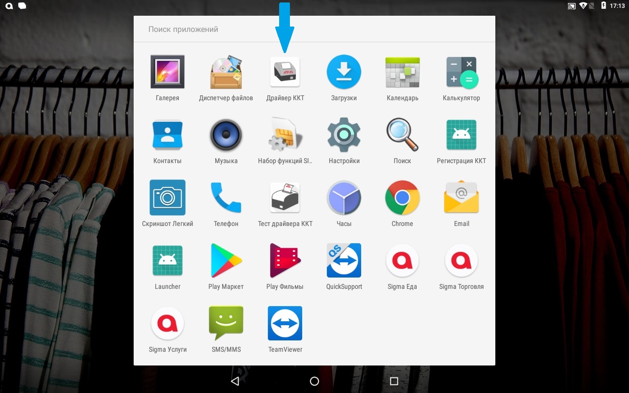
Нажмите на Параметры ККТ
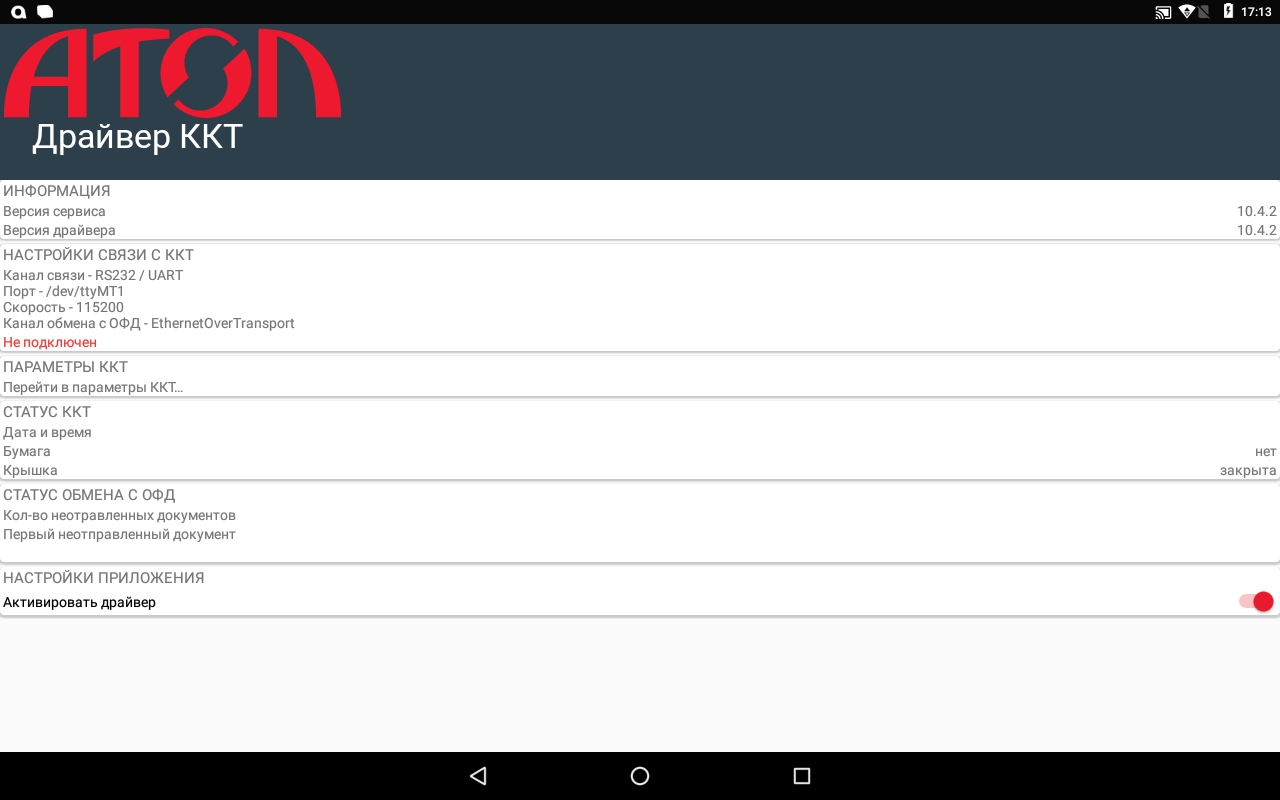
Перейдите в раздел 1 Основные
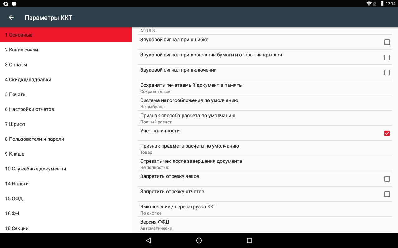
Найдите из списка «Отрезать чек после завершения документа»
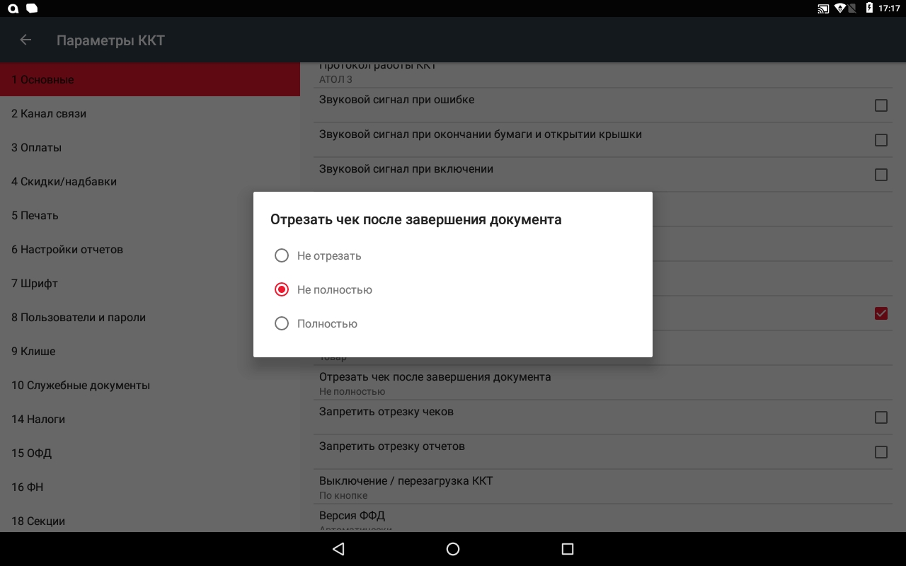
Выберите пункт «Не отрезать»
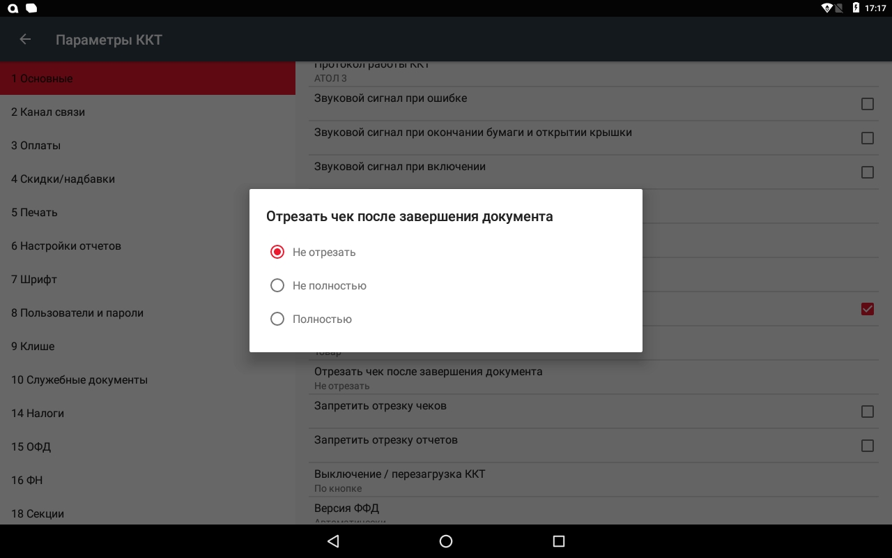
Далее проставьте галочки напротив «Запретить отрезку чеков» и «Запретить отрезку отчетов»
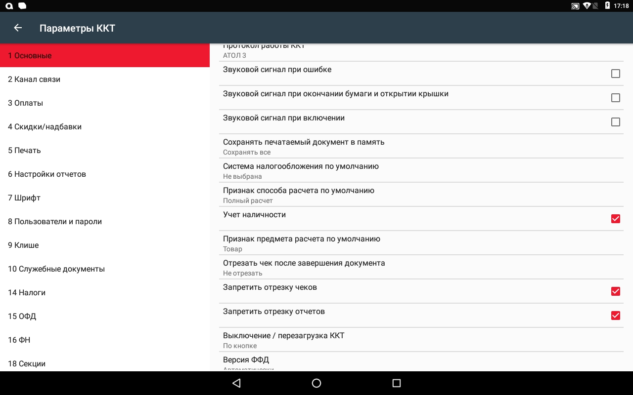
Нажмите на стрелку в левом верхнем углу и примените настройки нажав на «ОК»
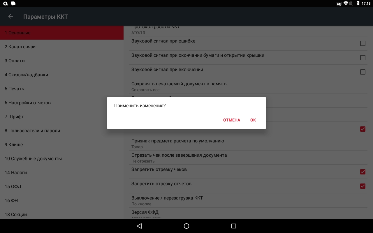
Можете дальше пробивать чеки без автоотреза. Далее необходимо обратиться к компанию, в которой вы приобрели смарт-терминал, для проведения ремонта автоотрезчика.
Ошибка 23
Данная ошибка указывает на некорректную скидку или надбавку к чеку.
Необходимо изменить количество или размер скидки/надбавки и повторить пробитие чека.
Ошибка 009 , 3
Данная ошибка означает, что фискальный регистратор занят другим приложением или потеряно соединение кассовой программы с фискальным регистратором.
Для решения данного вопроса необходимо:
-
перезагрузить смарт-терминал.
-
закрыть все сторонние приложения.
-
запустить заново кассовую программу и продолжить работу.
Ошибка 218
Ошибка 218 означает, что в фискальном регистраторе сбилось время.
Установить его по инструкции:
SIGMA 7 — Инструкция
SIGMA 8 и 10 — Инструкция
Ошибка 194
Ошибка возникает при печати чека возврата за другой день. Не даёт сделать возврат, т.к. в кассе недостаточно средств для возврата.
Для устранения ошибки нужно сделать внесение на необходимую сумму и снова провести возврат.
Как сделать внесение: Инструкция
Ошибка 11
При возникновении ошибки 11 (обычно на SIGMA 10) необходимо:
1) Свернуть все приложения
2) Нажать на кнопку вызова главного меню на планшете.
3) Удалить приложение «Launcher», зажав значок и перетащить на кнопку «Удалить» в правом верхнем углу.
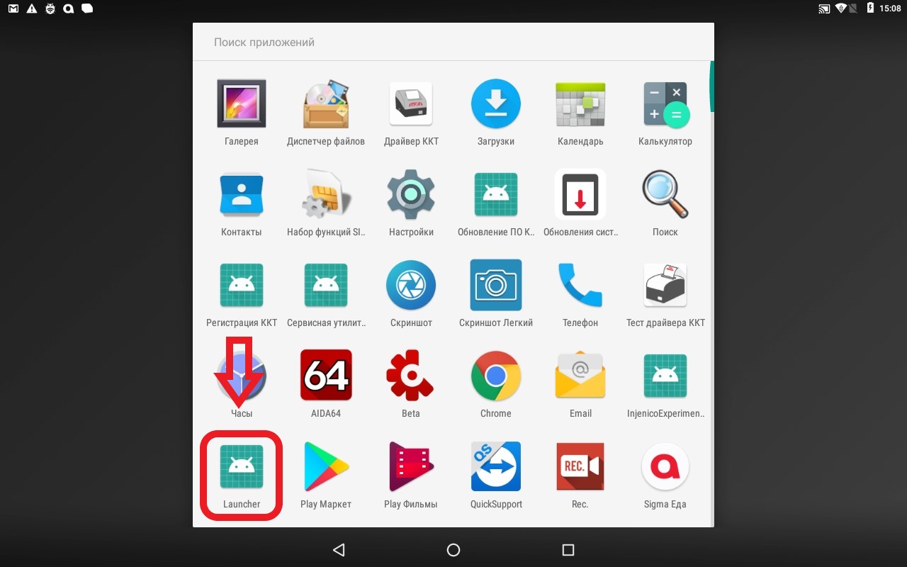
4) Таким же образом удалите «Тест драйвера ККТ». Не путать с «Драйвер ККТ»!
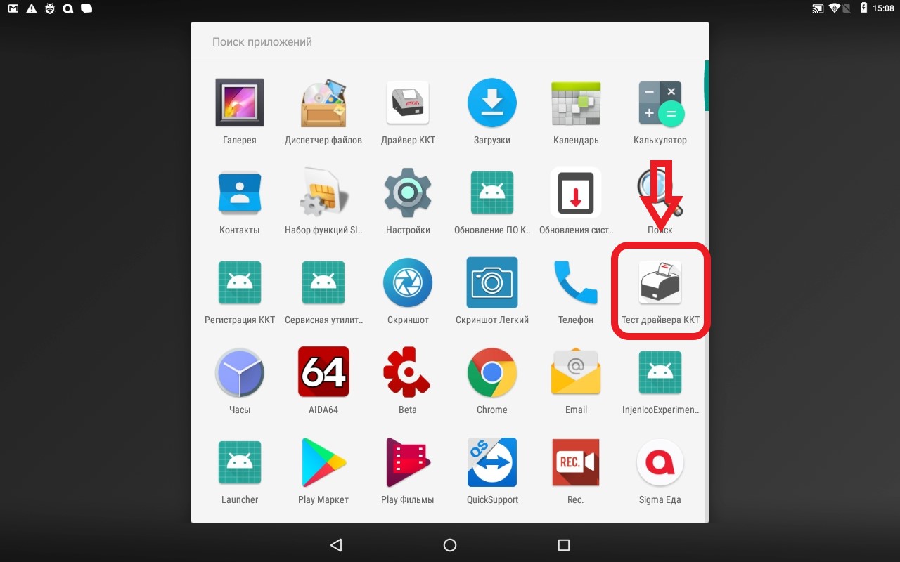
5) Далее перезагрузите смарт-терминал и продолжайте работу в кассовом приложении.
Если не помогло, проверьте соединение с драйвером кассового оборудования по инструкции.
Ошибка 235, 137
Ошибка ФН 235 связана с тем, что документы не передаются в ОФД. ФН хранит дату первого из непереданных документов и ждет 30 дней. Если документ не отправляется, ФН перестаёт выдавать фискальный признак, и касса выдаёт ошибку 235.
Ошибка 137 связана с тем, что ресурс хранения документов исчерпан. Это означает, что касса не отправляет чеки в ОФД.
Срок действия ФН можно проверить в приложении SIGMA:
Как проверить срок действия ФН?
Для решения данных ошибок следуйте инструкции:
SIGMA 7
SIGMA 8
SIGMA 10
Ошибка 65
Для решения ошибки 65 «переполнение буфера ЭЖ» (возникает на Sigma 7) нужно сделать следующие действия:
1. Зайти в Администрирование ккт/сервисную утилиту.
Она находится в списке приложений либо в настройках, если у вас новая версия сервисной утилиты:
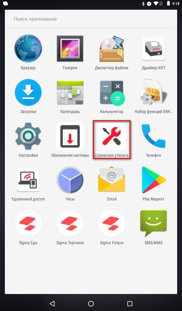
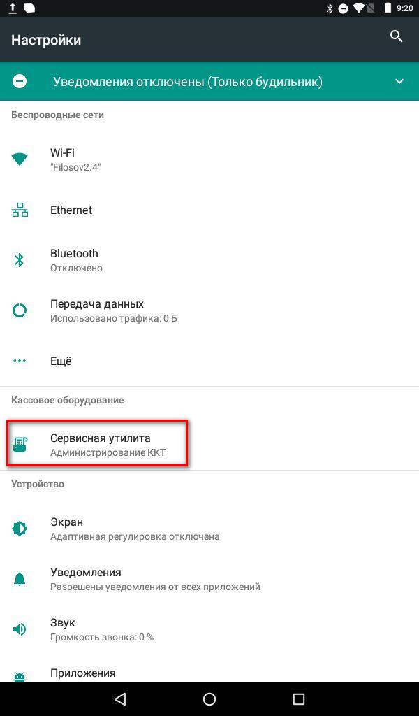
2. Выбрать пункт «Сервисные операции».
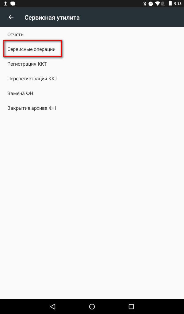
3. В операциях выбрать пункт «техобнуление».
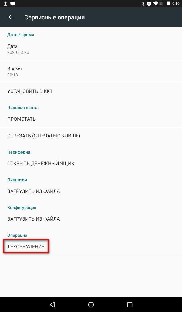
4. Далее нужно будет перезагрузить кассовый аппарат.
После выполнения всех описанных действий ошибка 65 перестанет возникать.
Ошибка 132
Данная ошибка означает, что недостаточно питания для работы фискального регистратора.
Необходимо подождать большего заряда аккумулятора.
Ошибка 44, 34, 148
Ошибка 44 , 34, 148.
Данная ошибка означает, что в фискальном регистраторе закончилась чековая лента.
Ошибка 116 , 133, 231
Данные ошибки указывают на неверные признаки кассы в настройках драйвера.
Для решения необходимо:
1. Зайти в режим настроек в «Драйвер ККТ» :
SIGMA 7 — Инструкция
SIGMA 8,10 — Инструкция
2. Перейти в раздел «Основные»
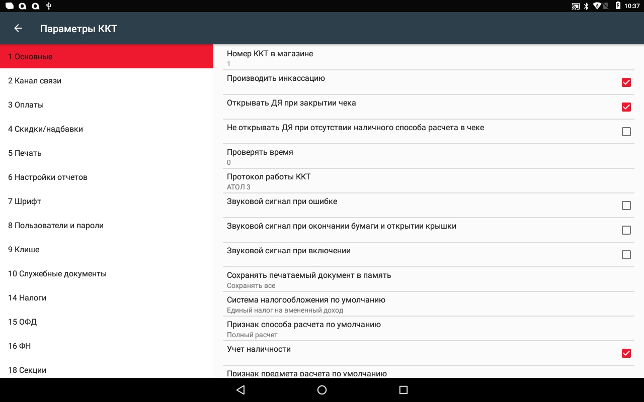
3. Выбрать пункт Система налогообложения по умолчанию.

4. Если выбрана неверная система налогообложения, выбрать верную. Далее применить настройки, нажав на кнопку «Назад» и сохранив настройки.
Если же указана верная система налогообложения, временно выбрать другую, далее применить настройки, нажав на кнопку «Назад» и сохранив настройки.
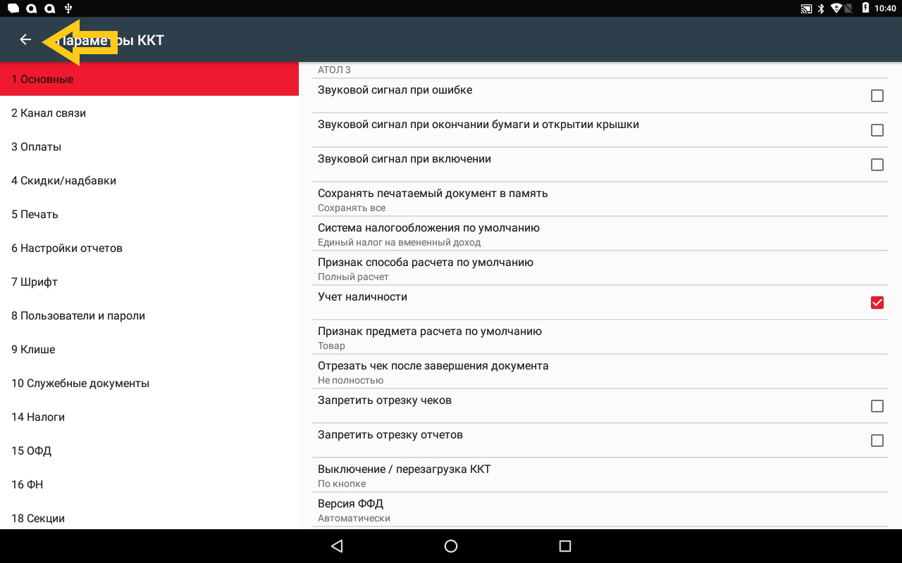
5. Возвращаемся в меню «Основные» и повторно выставляем верную систему налогообложения. Далее применить настройки, нажав на кнопку «Назад» и сохранив настройки.
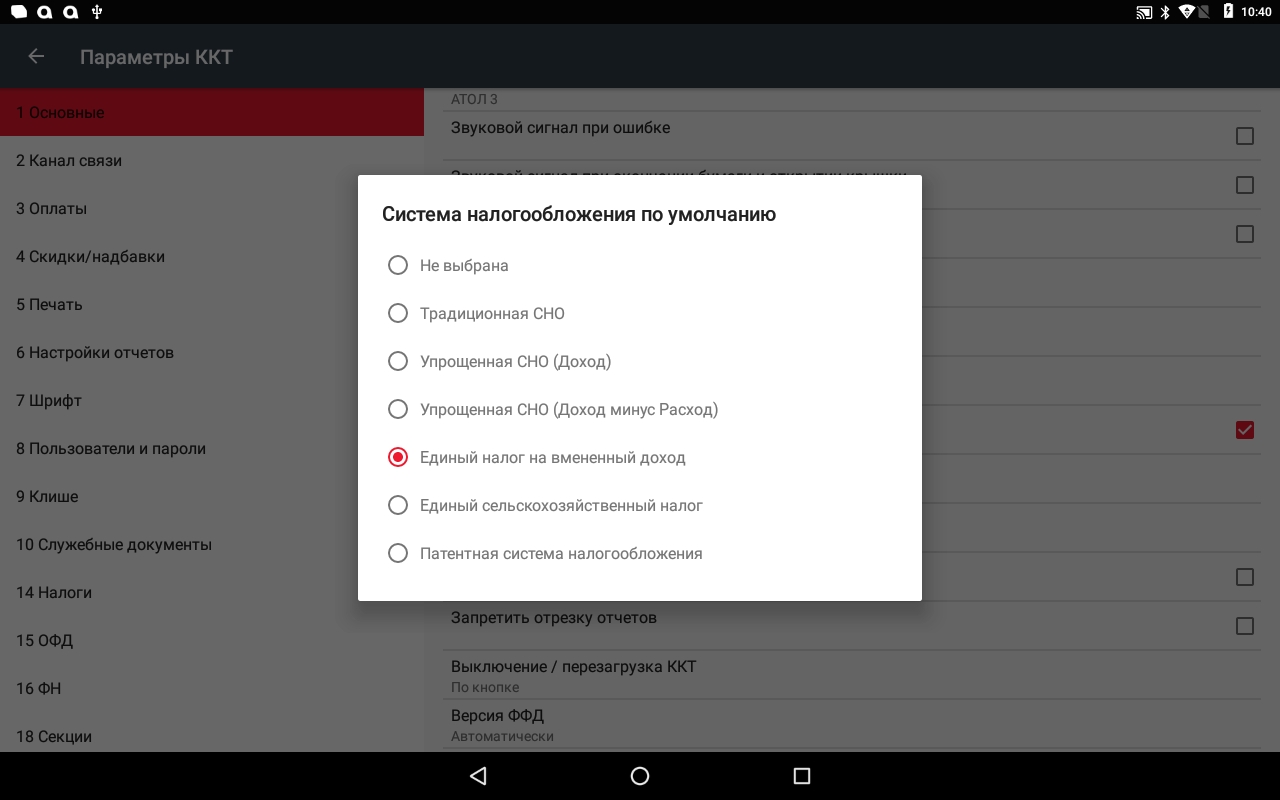
6. Далее в приложении SIGMA переподключаем фискальный.
Если фискальный регистратор сразу подключен, отключаем его и подключаем повторно.
При ошибке 116 необходимо еще проверить признаки кассы, выставленные в фискальном накопителе.
В администрировании ККТ переходим в раздел «Перерегистрация ККТ» и проверяем признаки.
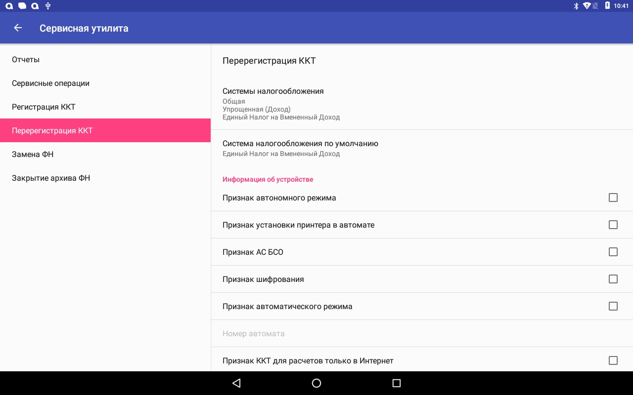
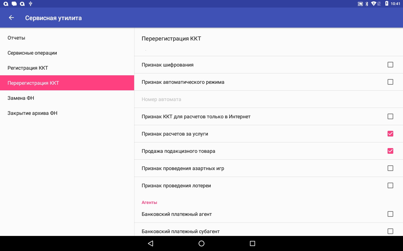
Если что-то указано неверно, меняем признаки и нажимаем «Перерегистрация ККТ», внизу страницы.
Уточнить параметры регистрации для кассы можно у компании, которая ставила кассу на учёт.
Необходимо обратить внимание на пункты:
«Продажа подакцизного товара» — используется только для продажи акцизных товаров
«Признак расчёта за услуги» — если на кассе пробиваются чеки на услуги
«Признак ККТ для расчетов только в Интернет» — используется только для оплаты на сайте интернет магазинов, в SIGMA данный функционал не поддерживается.
Если у вас основная система налогообложения (ОСН) , необходимо использовать ФН на 15 месяцев. При неверном выборе объёма фискального накопителя, будет возникать ошибка 116.
Ошибка 1, 2
Данная ошибка указывает на отсутствие связи приложения с фискальным регистратором.
Если возникает ошибка печати 1 или 2 необходимо сделать следующее:
Выйти из приложения на основной экран и зайти в список приложений.
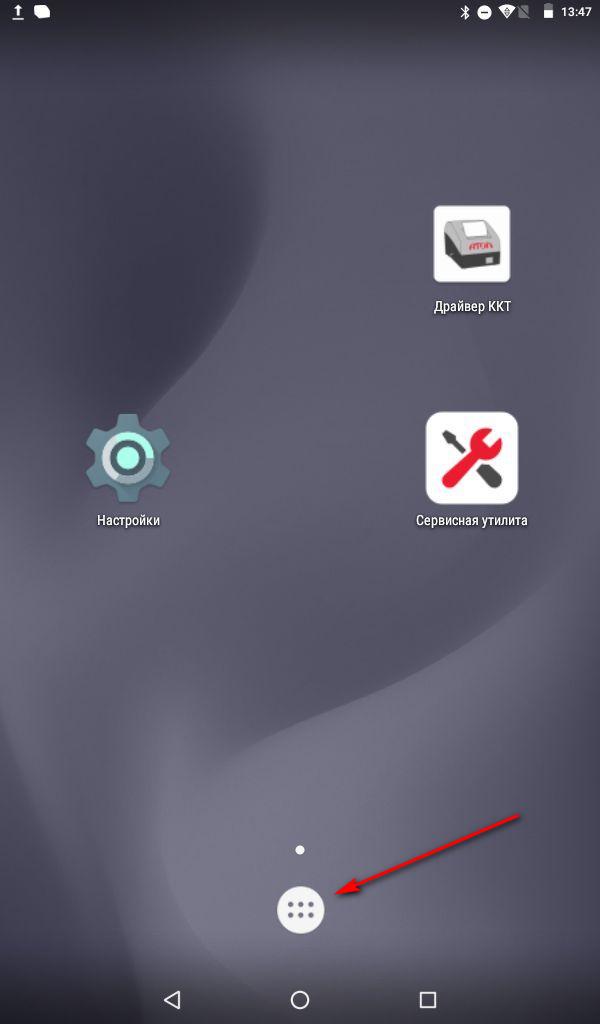
выбрать приложение драйвер ККТ.
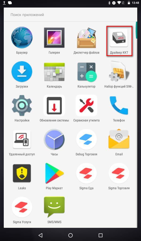
Переподключить драйвер, нажав 2 раза на переключатель.
Если эти действия не помогли, то перезагрузите смарт-терминал.
Ошибки с закрытием смены ( 68, 83 )
При возникновении ошибок с номером 68 и 83, необходимо закрыть смену и открыть её снова.
Для этого зайдите в раздел «Кассовые операции».
Нажмите «Закрыть смену».
Откройте смену и продолжите работу.
Ошибка 115, 142, 218
Данная ошибка встречается на смарт-терминале SIGMA 7.
Она означает, что на кассовом терминале сбилось время в сервисной утилите.
Для решения необходимо перезагрузить смарт-терминал.
Если это не помогло, то сделайте следующие действия: Ввод даты и времени
Ошибка 182 и 96
Ошибка связанна с отсутствием лицензий для ККТ.
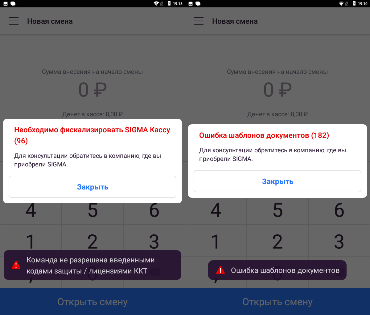
Для решения возникшей ошибки необходимо запросить лицензии через обращение в службу поддержки или у компании где приобретался смарт-терминал.
В обращении нужно указать заводской номер кассы и номер ошибки.
После получения лицензий необходимо выполнить следующую инструкцию: Загрузка лицензий
Ошибка 207
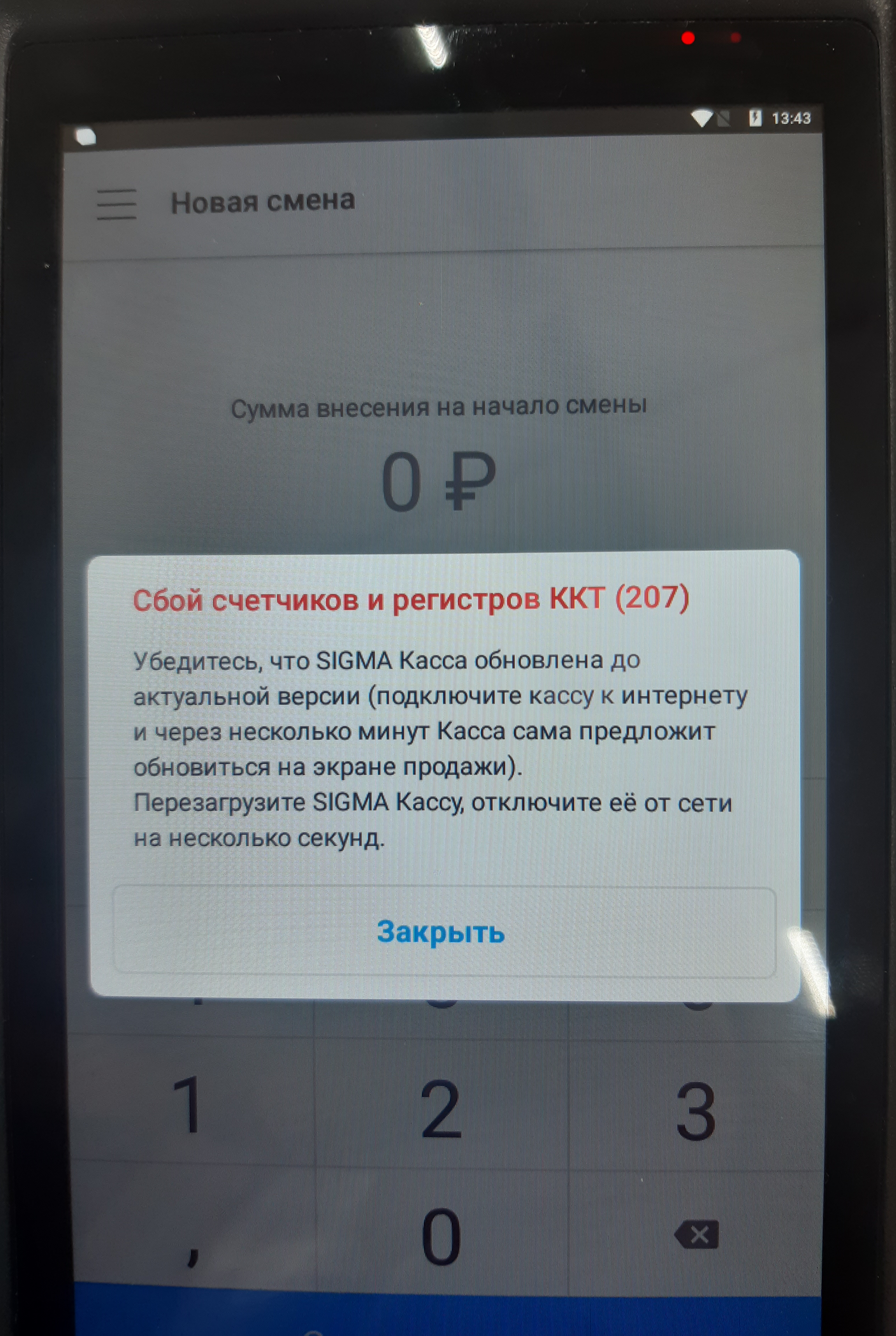
Сбой счетчиков и регистров ККТ (207) возникает во время открытия смены.
Для её устранения необходимо выполнить тех.обнуление на ККТ: Тех.обнуление
Ошибка 12
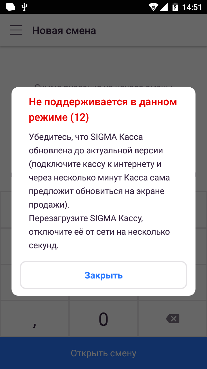
Ошибка «Не поддерживается в данном режиме (12)» означает, что в дККТ не указан важный параметр (UIN).
Для решения возникшей ошибки необходимо обратиться в компанию, где приобретался смарт-терминал для ввода данного параметра в дККТ.
Guidesimo.com webproject is not a service center of KAESER KOMPRESSOREN trademark and does not carries out works for diagnosis and repair of faulty KAESER KOMPRESSOREN SIGMA CONTROL 2 equipment. For quality services, please contact an official service center of KAESER KOMPRESSOREN company. On our website you can read and download documentation for your KAESER KOMPRESSOREN SIGMA CONTROL 2 device for free and familiarize yourself with the technical specifications of device.