
- Manuals
- Brands
- Mitsubishi Manuals
- Air Conditioner
- PUHY-P250YJM-A
- Service handbook
-
Contents
-
Table of Contents
-
Troubleshooting
-
Bookmarks
Quick Links
Related Manuals for Mitsubishi PUHY-P250YJM-A
Summary of Contents for Mitsubishi PUHY-P250YJM-A
-
Page 2: Safety Precautions
Do not touch the heat exchanger fins. It may also be in violation of applicable laws. The fins are sharp and dangerous. MITSUBISHI ELECTRIC CORPORATION cannot be held responsible for malfunctions or accidents resulting from the In the event of a refrigerant leak, thoroughly ventilate use of the wrong type of refrigerant.
-
Page 3
MITSUBISHI may result in smoke, fire, and/or explosion. When installing the unit in a small room, exercise cau- tion and take measures against leaked refrigerant Only use accessories recommended by MITSUBISHI. -
Page 4
Precautions for handling units for use with R410A CAUTION Do not use the existing refrigerant piping. Use a vacuum pump with a reverse-flow check valve. A large amount of chlorine that may be contained in the re- If a vacuum pump that is not equipped with a reverse-flow sidual refrigerant and refrigerating machine oil in the exist- check valve is used, the vacuum pump oil may flow into the ing piping may cause the refrigerating machine oil in the… -
Page 5: Before Installing The Unit
Before installing the unit WARNING Do not install the unit where a gas leak may occur. When installing the unit in a hospital, take appropriate measures to reduce noise interference. If gaseous refrigerant leaks and piles up around the unit, it may be ignited.
-
Page 6: Electrical Work
Before installing the unit (moving and reinstalling the unit) and performing electrical work CAUTION Properly ground the unit. Periodically check the installation base for damage. Do not connect the grounding wire to a gas pipe, water pipe, If the unit is left on a damaged platform, it may fall and lightning rod, or grounding wire from a telephone pole.
-
Page 7
Before the test run CAUTION Turn on the unit at least 12 hours before the test run. Do not operate the unit without panels and safety guards. Keep the unit turned on throughout the season. If the unit is turned off in the middle of a season, it may result in malfunc- Rotating, high-temperature, or high-voltage parts on the unit tions. -
Page 8: Table Of Contents
CONTENTS I Read Before Servicing [1] Read Before Servicing………………….3 [2] Necessary Tools and Materials ………………..4 [3] Piping Materials ……………………5 [4] Storage of Piping ……………………7 [5] Pipe Processing……………………7 [6] Brazing……………………….8 [7] Air Tightness Test……………………9 [8] Vacuum Drying (Evacuation) ………………..
-
Page 9
HWE1018A… -
Page 10: Read Before Servicing
I Read Before Servicing [1] Read Before Servicing ………………….. 3 [2] Necessary Tools and Materials………………4 [3] Piping Materials ……………………. 5 [4] Storage of Piping ………………….. 7 [5] Pipe Processing ……………………. 7 [6] Brazing……………………..8 [7] Air Tightness Test ………………….9 [8] Vacuum Drying (Evacuation) ……………….
-
Page 11
— 2 — HWE1018A… -
Page 12: Read Before Servicing
[ I Read Before Servicing ] I Read Before Servicing [1] Read Before Servicing 1. Check the type of refrigerant used in the system to be serviced. Refrigerant Type New refrigerant series split-type air-conditioners for computer rooms R410A 2. Check the symptoms exhibited by the unit to be serviced. Refer to this service handbook for symptoms relating to the refrigerant cycle.
-
Page 13: Necessary Tools And Materials
[ I Read Before Servicing ] [2] Necessary Tools and Materials Prepare the following tools and materials necessary for installing and servicing the unit. Tools for use with R410A (Adaptability of tools that are for use with R22 or R407C) 1.
-
Page 14: Piping Materials
[ I Read Before Servicing ] [3] Piping Materials Do not use the existing piping! 1. Copper pipe materials O-material (Annealed) Soft copper pipes (annealed copper pipes). They can easily be bent with hands. 1/2H-material (Drawn) Hard copper pipes (straight pipes). They are stronger than the O-material (Annealed) at the same radial thickness.
-
Page 15
[ I Read Before Servicing ] 4. Thickness and refrigerant type indicated on the piping materials Ask the pipe manufacturer for the symbols indicated on the piping material for new refrigerant. 5. Flare processing (O-material (Annealed) and OL-material only) The flare processing dimensions for the pipes that are used in the R410A system are larger than those in the R22 system. Flare processing dimensions (mm[in]) A dimension (mm) Pipe size (mm[in]) -
Page 16: Storage Of Piping
[ I Read Before Servicing ] [4] Storage of Piping 1. Storage location Store the pipes to be used indoors. (Warehouse at site or owner’s warehouse) If they are left outdoors, dust, dirt, or moisture may infiltrate and contaminate the pipe. 2.
-
Page 17: Brazing
[ I Read Before Servicing ] [6] Brazing No changes have been made in the brazing procedures. Perform brazing with special care to keep foreign objects (such as oxide scale, water, and dust) out of the refrigerant system. Example: Inside the brazed connection Use of oxidized solder for brazing Use of non-oxidized solder for brazing 1.
-
Page 18: Air Tightness Test
[ I Read Before Servicing ] [7] Air Tightness Test No changes have been made in the detection method. Note that a refrigerant leak detector for R22 will not detect an R410A leak. Halide torch R22 leakage detector 1. Items to be strictly observed Pressurize the equipment with nitrogen up to the design pressure (4.15MPa[601psi]), and then judge the equipment’s air tight- ness, taking temperature variations into account.
-
Page 19: Vacuum Drying (Evacuation)
[ I Read Before Servicing ] [8] Vacuum Drying (Evacuation) (Photo1) 15010H (Photo2) 14010 Recommended vacuum gauge: ROBINAIR 14010 Thermistor Vacuum Gauge 1. Vacuum pump with a reverse-flow check valve (Photo1) To prevent the vacuum pump oil from flowing into the refrigerant circuit during power OFF or power failure, use a vacuum pump with a reverse-flow check valve.
-
Page 20: Refrigerant Charging
[ I Read Before Servicing ] [9] Refrigerant Charging Cylinder with a siphon Cylinder without a siphon Cylin- Cylin- Cylinder color R410A is pink. Refrigerant charging in the liquid state Valve Valve liquid liquid 1. Reasons R410A is a pseudo-azeotropic HFC blend (boiling point R32=-52°C[-62°F], R125=-49°C[-52°F]) and can almost be handled the same way as a single refrigerant, such as R22.
-
Page 21: Characteristics Of The Conventional And The New Refrigerants
[ I Read Before Servicing ] [11] Characteristics of the Conventional and the New Refrigerants 1. Chemical property As with R22, the new refrigerant (R410A) is low in toxicity and chemically stable nonflammable refrigerant. However, because the specific gravity of vapor refrigerant is greater than that of air, leaked refrigerant in a closed room will accumulate at the bottom of the room and may cause hypoxia.
-
Page 22: Notes On Refrigerating Machine Oil
[ I Read Before Servicing ] [12] Notes on Refrigerating Machine Oil 1. Refrigerating machine oil in the HFC refrigerant system HFC type refrigerants use a refrigerating machine oil different from that used in the R22 system. Note that the ester oil used in the system has properties that are different from commercially available ester oil. Refrigerant Refrigerating machine oil Mineral oil…
-
Page 23
[ I Read Before Servicing ] — 14 — HWE1018A… -
Page 24: Restrictions
II Restrictions [1] System configuration ………………….. 17 [2] Types and Maximum allowable Length of Cables …………18 [3] Switch Settings and Address Settings …………….20 [4] An Example of a System to which an MA Remote Controller is connected….. 24 [5] Restrictions on Pipe Length …………………
-
Page 25
— 16 — HWE1018A… -
Page 26: System Configuration
PUHY-P250YJM-A PFD-P500VM-E PUHY-P250YJM-A x 2 *1 *1 When two outdoor units are connected to one indoor unit, two refrigerant circuits must be connected. Only one refrigerant circuit can be connected to the indoor unit at factory shipment. To connect two refrigerant circuits, per- form some work on the unit.
-
Page 27: Types And Maximum Allowable Length Of Cables
[ II Restrictions ] [2] Types and Maximum allowable Length of Cables 1. Wiring work (1) Notes 1) Have all electrical work performed by an authorized electrician according to the local regulations and instructions in this man- ual. 2) Install external transmission cables at least 5cm [1-31/32″] away from the power supply cable to avoid noise interference. (Do not put the control cable and power supply cable in the same conduit tube.) 3) Provide grounding for the outdoor unit as required.
-
Page 28
[ II Restrictions ] 2) Remote controller wiring MA remote controller Type Number of 2-core cable Cable type cores 2 *1 0.3 to 1.25mm Cable size [AWG22 to 16] Maximum overall line 200m [656ft] max. length *1 The use of cables that are smaller than 0.75mm [AWG18] is recommended for easy handling. -
Page 29: Switch Settings And Address Settings
[ II Restrictions ] [3] Switch Settings and Address Settings 1. Switch setting Refer to section «[4] An Example of a System to which an MA Remote Controller is connected» before performing wiring work. Set the switches while the power is turned off. If the switch settings are changed while the unit is being powered, those changes will not take effect, and the unit will not function properly.
-
Page 30
[ II Restrictions ] (3) Settings of MA remote controller Main/Sub switching switch (When MA remote controller is used: factory setting «Main») Main/sub settings are available on the MA remote controller. When two remote controllers are connected, set either of them to «Sub». -
Page 31: Demand Control
[ II Restrictions ] CAUTION 1) Wiring should be covered by insulation tube with supplementary insulation. 2) Use relays or switches with IEC or equivalent standard. 3) The electric strength between accessible parts and control circuit should have 2750V or more. Example of wiring connection CN51 CN3S…
-
Page 32
[ II Restrictions ] *3. If wrong sequence of steps are taken, the units may go into the Thermo-OFF (compressor stop) mode. Ex) When switching from 100% to 50% (Incorrect) 100% to 0% to 50% : The units may go into the Thermo-OFF mode. (Correct) 100% to 75% to 50% *4. -
Page 33: An Example Of A System To Which An Ma Remote Controller Is Connected
[ II Restrictions ] [4] An Example of a System to which an MA Remote Controller is connected 1. System with one refrigerant (1) Sample control wiring Leave the male Leave the male connector on connector on CN41 as it is. CN41 as it is.
-
Page 34
[ II Restrictions ] Shielded cable connection (4) Wiring method Connect the earth terminal of the OC and S terminal of 1) Indoor/outdoor transmission line the IC terminal block (TB5-1). Connect M1, M2 terminals of the indoor/outdoor trans- 2) Switch setting mission line terminal block (TB3) on the outdoor unit (OC Address setting is required as follows. -
Page 35
[ II Restrictions ] 2. System with two refrigerant circuits (1) Sample control wiring CN41 CN40 Replace TB5-1 *Two indoor controllers (controller circuit boards) M1M2S M1M2 A1 B1 S are equipped in the indoor unit (P500). TB15 Connect Leave the male connector on CN41 as it is. -
Page 36
[ II Restrictions ] on the controller board from the female power supply (4) Wiring method switch connector (CN41), and connect it to the female 1) Indoor/outdoor transmission line power supply switch connector (CN40) on only one of the Connect M1, M2 terminals of the indoor/outdoor trans- outdoor units. -
Page 37
[ II Restrictions ] 3. System in which two MA remote controllers are connected to one indoor unit (1) Sample control wiring Leave the male Leave the male connector on connector on CN41 as it is. CN41 as it is. TB5-1 *Two indoor controllers (controller circuit boards) M1M2… -
Page 38
[ II Restrictions ] Set the Main/Sub switch on the connected MA remote (4) Wiring method controllers (option) to SUB.(See the installation manual 1) Indoor/outdoor transmission line for the MA remote controller for the setting method.) Same as [4] 1. 3) Switch setting 2) MA remote controller wiring Address setting is required as follows. -
Page 39
[ II Restrictions ] 4. System in which two indoor units are grouped with the MA remote controller (1) Sample control wiring Leave the male Leave the male Leave the male Leave the male connector on connector on connector on connector on CN41 as it is. -
Page 40
[ II Restrictions ] Set the Main/Sub switch on one of the MA remote con- (4) Wiring method trollers to SUB. 1) Indoor/outdoor transmission line 3) Switch setting Same as [4] 1. Address setting is required as follows. 2) MA remote controller wiring Group operation of indoor units To perform a group operation of indoor units (IC), daisy- chain terminals 1 and 2 on the terminal block (TB15) on… -
Page 41: Restrictions On Pipe Length
[ II Restrictions ] [5] Restrictions on Pipe Length 1. Sample connection (1) System with one refrigerant circuit (P500 model) Outdoor unit Indoor Unit: m [ft] Operation Pipe sections Allowable length of pipes Length Between outdoor units 10 [32] or less Total pipe length (L) from the outdoor unit to A(B)+C 165 [541] or less…
-
Page 42
[ II Restrictions ] 2. Refrigerant pipe size (1) Diameter of the refrigerant pipe between the outdoor unit and the first branch (outdoor unit pipe size) Outdoor unit set name Liquid pipe size (mm) [inch] Gas pipe size (mm) [inch] (total capacity) 250 model ø9.52 [3/8″] *1… -
Page 43
[ II Restrictions ] — 34 — HWE1018A… -
Page 44: Outdoor Unit Components
III Outdoor Unit Components [1] Outdoor Unit Components and Refrigerant Circuit …………37 [2] Control Box of the Outdoor Unit………………39 [3] Outdoor Unit Circuit Board………………..40 — 35 — HWE1018A…
-
Page 45
— 36 — HWE1018A… -
Page 46: Outdoor Unit Components And Refrigerant Circuit
[ III Outdoor Unit Components ] III Outdoor Unit Components [1] Outdoor Unit Components and Refrigerant Circuit 1. PUHY-P250YJM-A (1) Front view of a outdoor unit Fan guard Control Control Control Heat exchanger Heat exchanger Heat exchanger Front panel Fin guard…
-
Page 47
[ III Outdoor Unit Components ] 2. PUHY-P250YJM-A (1) Refrigerant circuit Low-pressure sensor(63LS) High-pressure sensor(63HS1) Check valve High-pressure switch(63H1) 4-way valve(21S4b) Accumulator 4-way valve(21S4a) Low-pressure check joint High-pressure check joint Subcool coil Compressor cover Linear expansion valve (LEV2) Linear expansion valve… -
Page 48: Control Box Of The Outdoor Unit
[ III Outdoor Unit Components ] [2] Control Box of the Outdoor Unit <HIGH VOLTAGE WARNING> Control box houses high-voltage parts. When opening or closing the front panel of the control box, do not let it come into contact with any of the internal components.
-
Page 49: Outdoor Unit Circuit Board
[ III Outdoor Unit Components ] [3] Outdoor Unit Circuit Board 1. Outdoor unit control board CN332 CNDC Serial communication signal input Output 18VDC CN801 Bus voltage input GND (INV board) Pressure switch Output 17VDC connection (Fan board) Serial communication signal output CNAC2 driving output LED1…
-
Page 50
[ III Outdoor Unit Components ] 2. M-NET board CNS2 CNIT Transmission line input/output for 12VDC input CN04 centralized control system CN102 Bus voltage input 5VDC input Power supply output for centralized control system Power supply detection output Indoor/outdoor transmission line input/output Power supply ON/OFF Grounding signal input… -
Page 51: Inv Board
[ III Outdoor Unit Components ] 3. INV board SC-P1 Rectifier diode output (P) Open: No-load operation setting CN5V RSH1 SC-P2 Short-circuited: Normal setting LED1 Overcurrent detection Bus voltage Input(P) Lit: Inverter in normal operation 5VDC output resistor Blink: Inverter error GND(Fan Board) Serial communication signal output…
-
Page 52: Fan Board
[ III Outdoor Unit Components ] 4. Fan board LED3 CN18V Lit during normal Input 18VDC Serial communication signal output CPU operation GND(Control board) Serial communication signal output CN21 Serial communication signal output GND(INV board) CNVDC Input 17VDC Bus voltage input CN22 GND(INV board) Input 5VDC…
-
Page 53: Noise Filter
[ III Outdoor Unit Components ] 5. Noise Filter Output Output (Rectified L2-N current) (Rectified L2-N current) Surge absorber circuit Surge absorber circuit Short circuit Short circuit Grounding F1,F2,F3,F4 Fuse 250VAC 6.3A Output Grounding CN1A Input CN1B TB21 TB22 TB23 TB24 Input Input/output(L1)
-
Page 54: Indoor Unit Components
IV Indoor Unit Components [1] External Dimensions ………………….47 [2] Indoor Unit Components and Internal Structure ………….. 49 [3] Control Box of the Indoor Unit………………53 [4] Indoor Unit Circuit Board………………..54 [5] Separating the top and bottom of the unit……………. 55 — 45 — HWE1018A…
-
Page 55
— 46 — HWE1018A… -
Page 56: External Dimensions
[ IV Indoor Unit Components ] IV Indoor Unit Components [1] External Dimensions 1. PFD-P250VM-E model Unit : mm — 47 — HWE1018A…
-
Page 57
[ IV Indoor Unit Components ] 2. PFD-P500VM-E model Unit : mm — 48 — HWE1018A… -
Page 58: Indoor Unit Components And Internal Structure
[ IV Indoor Unit Components ] [2] Indoor Unit Components and Internal Structure 1. PFD-P250VM-E model (1) Front view of a indoor unit Panel for air filter maintenance Panel for refrigerant circuit maintenance Operation panel (remote controller) Lock key X 2 Panel for controller/fan related parts maintenance Display lamp (2) Rear view of a indoor unit…
-
Page 59
[ IV Indoor Unit Components ] (3) Front view of internal structure Suction temperature thermistor (on the right side of heat exchanger) Linear expansion valve (LEV) Air filter Heat exchanger X 2 (front / back) Sub drain pan Drain pan Drain hose Pulley X 2 Pipes (gas/liquid) -
Page 60
[ IV Indoor Unit Components ] 2. PFD-P500VM-E model (1) Front view of a indoor unit Panel for air filter maintenance Panel for refrigerant circuit maintenance Operation panel (remote controller) Display lamp Panel for controller maintenance Lock key X 4 Panel for fan related parts maintenance (2) Rear view of a indoor unit — 51 -… -
Page 61
[ IV Indoor Unit Components ] (3) Front view of internal structure Air filter Suction temperature thermistor (on the right side of heat exchanger) Sub drain pan Heat exchanger X 2 (front:No. 1; back:No. 2) Linear expansion valve (LEV) Drain pan Pulley X 2 Drain hose Bearing… -
Page 62: Control Box Of The Indoor Unit
[ IV Indoor Unit Components ] [3] Control Box of the Indoor Unit 1. PFD-P250VM-E model Relay(X11,Z1,Z3) Transformer Controller board Electro magnetic contactor (52F) Surge breaker (51F) Fuse (F1) Motor wiring Surge absorber board Circuit board for external I/O Power supply terminal bed Terminal block for transmission line (upper) Terminal block for MA remote controller (lower) 2.
-
Page 63: Indoor Unit Circuit Board
[ IV Indoor Unit Components ] [4] Indoor Unit Circuit Board 1. PFD-P250,P500VM-E models (1) Indoor Control Board CN3A Remote controller connection CN33 Power supply output Lamp output (to transformer) CN60 CN51 CN90 LEV output Drain pump Switch input Power supply Fan output output CN24…
-
Page 64: Separating The Top And Bottom Of The Unit
[ IV Indoor Unit Components ] [5] Separating the top and bottom of the unit The top and the bottom of the unit can be separated. (Requires brazing) When separating the top and the bottom of the unit, perform the work on a level surface. Follow the procedures below when separating the sections.
-
Page 65
[ IV Indoor Unit Components ] <Model 250> Connect the wire from the lamp assy. Bend the wire once, and fix the wire. (the wire from the lamp assy.) Fix the wire from the fan motor. Connect the wire from the lamp assy. <Model 500>… -
Page 66
[ IV Indoor Unit Components ] <Model 250> Unbraze these sections Heat exchanger (2 places on the gas pipe/ (liquid pipe) expanded part) Heat exchanger (gas pipe) Unbraze this section (1 place on the liquid pipe/ upper part of the strainer) Drain pan Unbraze these sections <Model 500>… -
Page 67
[ IV Indoor Unit Components ] To put the top and bottom sections of the unit together, follow the procedures above in the reverse order. Check to make sure that the frame is perpendicular to the horizontal plane before putting the panels together. When the frames will not fit back into place, loosen bolt 2 as shown in [Fig.1], place the frames, and tighten bolt 2 . -
Page 68: Electrical Wiring Diagram
V Electrical Wiring Diagram [1] Electrical Wiring Diagram of the Outdoor Unit …………..61 [2] Electrical Wiring Diagram of the Indoor Unit …………..62 — 59 — HWE1018A…
-
Page 69
— 60 — HWE1018A… -
Page 70: Electrical Wiring Diagram Of The Outdoor Unit
[ V Electrical Wiring Diagram ] V Electrical Wiring Diagram [1] Electrical Wiring Diagram of the Outdoor Unit 1. Electrical wiring diagram of the outdoor unit (1) PUHY-P250YJM-A — 61 — HWE1018A…
-
Page 71: Electrical Wiring Diagram Of The Indoor Unit
[ V Electrical Wiring Diagram ] [2] Electrical Wiring Diagram of the Indoor Unit 1. PFD-P250VM-E — 62 — HWE1018A…
-
Page 72
[ V Electrical Wiring Diagram ] 2. PFD-P500VM-E — 63 — HWE1018A… -
Page 73
[ V Electrical Wiring Diagram ] — 64 — HWE1018A… -
Page 74: Refrigerant Circuit
VI Refrigerant Circuit [1] Refrigerant Circuit Diagram ………………… 67 [2] Principal Parts and Functions ………………70 — 65 — HWE1018A…
-
Page 75
— 66 — HWE1018A… -
Page 76: Refrigerant Circuit Diagram
[ VI Refrigerant Circuit ] VI Refrigerant Circuit [1] Refrigerant Circuit Diagram 1. System with one refrigerant (1) PUHY-P250YJM-A 21S4b 21S4a TH23 63H1 63HS1 63LS SV1a COMP TH22 SV5b LEV2 LEV1 SCC (HIC Circuit) — 67 — HWE1018A…
-
Page 77
[ VI Refrigerant Circuit ] (2) PUHY-P500YSJM-A 21S4b 21S4a 63H1 63HS1 63LS SV1a Gas twinning pipe COMP TH23 SV5b ST2 BV2 LEV1 LEV2 (HIC circuit) 21S4b 21S4a 63H1 63HS1 63LS TH22 SV1a Liquid twinning pipe COMP SV5b ST2 BV2 LEV1 LEV2 (HIC circuit) — 68 -… -
Page 78
[ VI Refrigerant Circuit ] 2. System with two refrigerant circuits (1) PUHY-P250YJM-A x 2 21S4b 21S4a 63H1 63HS1 63LS SV1a COMP TH23-1 TH23-2 SV5b ST2 BV2 LEV1 LEV2 (HIC Circuit) 21S4b 21S4a 63H1 63HS1 63LS TH22-1 TH22-2 SV1a COMP… -
Page 79: Principal Parts And Functions
[ VI Refrigerant Circuit ] [2] Principal Parts and Functions 1. Outdoor unit Part Symbols Notes Usage Specifications Check method name (functions) Com- Adjusts the amount of circulating 250 models pressor (Comp1) refrigerant by adjusting the operat- Low-pressure shell scroll ing frequency based on the oper- compressor ating pressure data…
-
Page 80
[ VI Refrigerant Circuit ] Part Symbols Notes Usage Specifications Check method name (functions) Thermis- 1) Detects discharge air temper- Degrees Celsius Resistance (Discharge) check ature = 7.465k = 4057 2) Provides high-pressure pro- 25/120 tection 7.465 4057 0°C[32°F] :698kohm 10°C[50°F] :413kohm 20°C[68°F] :250kohm 30°C[86°F] :160kohm… -
Page 81
[ VI Refrigerant Circuit ] Part Symbols Notes Usage Specifications Check method name (functions) Linear LEV1 Adjusts the amount of bypass flow DC12V Same as in- expan- (SC control) from the liquid pipe on the outdoor Opening of a valve driven by a door LEV sion unit during cooling… -
Page 82
[ VI Refrigerant Circuit ] 2. Indoor unit Part Symbols Notes Usage Specifications Check method name (functions) Linear ex- 1) Adjusts superheat at the DC12V Continuity check pansion Opening of a valve driven by with a tester heat exchanger outlet of the valve a stepping motor Continuity be-… -
Page 83
[ VI Refrigerant Circuit ] — 74 — HWE1018A… -
Page 84: Control
VII Control [1] Functions and Factory Settings of the Dipswitches …………77 [2] Controlling the Outdoor Unit ……………….. 82 [3] Controlling the Indoor Unit ………………..94 [4] Operation Flow Chart………………….. 98 — 75 — HWE1018A…
-
Page 85
— 76 — HWE1018A… -
Page 86: Functions And Factory Settings Of The Dipswitches
[ VII Control ] VII Control [1] Functions and Factory Settings of the Dipswitches 1. Outdoor unit (1) Control board Units that re- quire switch Function according to switch setting Switch setting timing setting Switch Function Note.2 Unit address setting Set to 51-100 with the dial switch Before power on For self-diagnosis/…
-
Page 87
[ VII Control ] Units that re- quire switch Function according to switch setting Switch setting timing setting Switch Function Note.2 Test run mode: en- SW3-2 disabled SW3-2 enabled Anytime after power on abled/disabled Test run mode: ON/ Sends a test-run After power on and when Stops all ICs signal to all ICs… -
Page 88
[ VII Control ] Units that re- quire switch Function according to switch setting Switch setting timing setting Switch Function Note.2 Model selection See the table below (Note 4) Before being energized Low-noise mode Capacity priority Low-noise mode Before being energized selection mode Note 3… -
Page 89
[ VII Control ] 2. Function of the switch (Indoor unit) (1) Dipswitches 1) SW1,3 Function according to switch setting Switch setting timing Notes Switch Function Not available Available Clogged filter detection Filter check reminder 100h 2500h time setting Remote display option Fan output Thermo-ON signal While the unit is stopped… -
Page 90
[ VII Control ] 3) SW5 Function Operation by switch setting Switch setting timing Reset of the integrated Resetting the integrated operation time During unit stoppage (remote controller OFF) operation time according to the setting of SW7-1 and 7-2 (when switching from OFF to ON) 4) SW8 Function Operation by switch setting… -
Page 91: Controlling The Outdoor Unit
[ VII Control ] [2] Controlling the Outdoor Unit -1- Outline of Control Method The outdoor units are designated as OC and OS in the order of capacity from large to small (if two or more units have the same capacity, in the order of address from small to large). The setting of outdoor unit can be verified by using the self-diagnosis switch (SW1).
-
Page 92
[ VII Control ] -5- Bypass Control Bypass solenoid valves (SV1a), which bypass the high- and low- pressure sides, perform the following functions. (1) Bypass solenoid valve (SV1a) (ON = Open), (SV9) (ON = Open) SV1a Operation When starting-up the compressor of each ON for 4 minutes. -
Page 93
[ VII Control ] -6- Compressor Frequency Control Depending on the capacity required, the frequency of the compressor is controlled to bring the evaporation temperature (Te) close to the target evaporation temperature (Tem) during cooling operation, and to keep constant condensing temperature (49°C[120°F] =2.88MPa[418psi]) during heating operation. -
Page 94: Defrost Operation Control
[ VII Control ] -7- Defrost Operation Control (1) Starting the defrost operation The defrost cycle starts when the pipe temperature (TH3) at or below the value in the table below has continuously been de- tected for three minutes after the cumulative compressor operation time of 50 minutes have passed (90 minutes when the defrost prohibit timer is set to 90 minutes.).
-
Page 95: Refrigerant Recovery Control
[ VII Control ] -8- Refrigerant Recovery Control Recovery of refrigerant is performed during heating operation to prevent the refrigerant from accumulating inside the unit while it is stopped (unit in fan mode), or inside the indoor unit that is in cooling mode or in heating mode with thermo off. It is also performed during cooling operation to prevent an excessive amount of refrigerant from accumulating in the outdoor heat ex- changer.
-
Page 96
[ VII Control ] -11- Refrigerant flow control (Linear expansion valve <LEV2>) Refrigerant flow is controlled by each unit in the combined models during heating. Refrigerant flow control is performed by the OC and OS individually. The valve opens to a specified angle during cooling (Opening: 2100 pulses) Valve opening is controlled based on the values of high pressure (63HS1), discharge temperature (TH4), low pressure( 63LS), and piping temperature (TH5). -
Page 97
[ VII Control ] -13- Emergency Operation Mode Backup mode is a mode in which the unit is operated when the thermistor malfunctions. The unit automatically goes into the backup mode when the following error is detected. (1) Starting the emergency operation 1) When an error occurs, the error source and the error code will be displayed on the display on the remote controller. -
Page 98
[ VII Control ] -14- Capacity Control between Outdoor Units (when two refrigerant circuits are connected) The following two capacity control methods between indoor units are available. Control to make only one of the outdoor units (which has the smaller address) operate and keep running during low-load hours at startup. -
Page 99
[ VII Control ] -17- DEMAND Control Cooling/heating operation can be prohibited (Thermo-OFF) by an external input to the indoor units. When DIP SW4-4 is set to ON, the 4-step DEMAND control is enabled. Eight-step demand control is possible in the system with two outdoor units. Refer to Chapter II [3] 2. -
Page 100
[ VII Control ] -18- System Rotation Control Instructions 1. General Descriptions Each group can consist of a maximum of 5 systems and a minimum of 2 systems. With the use of this control function, one system in a given group serves as a backup and remains stopped. The unit designated as the control unit (System 1 in Figure 1) sends command signals to other units in the group to start or stop, and rotates the backup unit every 480 hours. -
Page 101
[ VII Control ] (1) Rotation Group Setting Group setting is required to enable the system rotation control function. Group setting must be made after the setup sequence for all applicable indoor and outdoor units have been completed. By turning the Dip SW5-10 from OFF to ON on the outdoor unit with the lowest odd number address in a given group while the unit is stopped, this unit is designated as the control unit. -
Page 102
[ VII Control ] (6) When an Error Occurs If an error is detected by a unit or a communication failure between the systems in the group while the rotation function is enabled, the units will perform the actions as described in Table 1, and the rotation control will be temporarily stopped. When the starting conditions are met, this function will be resumed, and the rotation sequence and the system rotation timer count effective at the time of error will be kept. -
Page 103: Controlling The Indoor Unit
[ VII Control ] [3] Controlling the Indoor Unit <Indoor unit control> There are two controller circuit boards with two refrigerant circuits inside the indoor unit of 20 HP. There is one controller circuit board with one refrigerant circuit. Each refrigerant circuit is controlled independently (in case of one refrigerant circuit, one-to-one control of indoor unit and outdoor unit) in the following method.
-
Page 104: Actuator Control
[ VII Control ] -2- Actuator Control (1) LEV Control · At startup, the LEV is set to the initial position based on the outside temperature. · After the start-up, the degree of LEV opening is controlled every minute so that the superheat detected by the thermistors TH22 (liquid pipe) and TH23 (gas pipe) of the indoor unit can be within a certain range.
-
Page 105
[ VII Control ] (3) Miscellaneous When the errors other than described in the chart, the unit makes an error stop without performing emergency operation. (Only the indoor fan operates, however; it stops when the fan is in trouble.) When one of the two refrigerant circuits, the outdoor unit with the refrigerant circuit in error performs emergency operation or makes an error stop, while the other outdoor unit keeps normal operation. -
Page 106
[ VII Control ] -7- Switching Between Pulse and Level of MA Remote Controller External Input The start/stop operation can be performed by either of the MA remote controller or the external input (pulse/level). DIPSW on the address circuit board (No.1 and No. 2) Valid operation SW1-9 = OFF External input (level) -
Page 107: Operation Flow Chart
[ VII Control ] [4] Operation Flow Chart 1. Mode determination flowchart (1) Indoor unit (cooling, heating, fan mode) Start Normal operation Error Breaker Unit in the stopped state turned on From outdoor unit Operation SW turned on 1. Protection function self-holding cancelled.
-
Page 108
[ VII Control ] (2) Outdoor unit (cooling and heating modes) Start Normal operation Error Breaker Unit in the stopped state turned on «HO» blinks in the room temperature display window on the remote controller. *Note 1 Indoor units registered to the remote controller From indoor unit Operation… -
Page 109
[ VII Control ] 2. Operations in each mode (1) Cooling operation Cooling operation Normal operation During test run mode 4-way valve OFF Unit in the stopped state Indoor unit fan *Note 1 operation Test run mode *Note 2 Thermostat ON 20-second restart prevention 1. -
Page 110
[ VII Control ] (2) Heating operation Normal operation Defrost operation Heating operation Unit in the stopped state *Note 1,2 During test run mode Defrost operation 4-way valve ON 4-way valve OFF 1. Indoor unit fan stops 2. Inverter defrost frequency control Test run mode 3. -
Page 111
[ VII Control ] — 102 — HWE1018A… -
Page 112: Test Run Mode
VIII Test Run Mode [1] Items to be checked before a Test Run …………….. 105 [2] Test Run Method ………………….106 [3] Operating Characteristic and Refrigerant Amount …………107 [4] Adjusting the Refrigerant Amount ……………… 107 [5] Refrigerant Amount Adjust Mode………………. 109 [6] The following symptoms are normal.
-
Page 113
— 104 — HWE1018A… -
Page 114: Items To Be Checked Before A Test Run
[ VIII Test Run Mode ] VIII Test Run Mode [1] Items to be checked before a Test Run (1) Check for refrigerant leak and loose cables and connectors. (2) Measure the insulation resistance between the power supply terminal block and the ground with a 500V megger and make sure it reads at least 1.0Mohm.
-
Page 115: Test Run Method
[ VIII Test Run Mode ] [2] Test Run Method Procedures Turn on the main power. It will take approximately three minute until the unit is operable. Leave the unit on for 12 hours (to power the outdoor unit compressor crankcase heater). Run an individual test on each of the refrigerant circuit to make sure that pipes or wires are not cross-connected.
-
Page 116: Operating Characteristic And Refrigerant Amount
[ VIII Test Run Mode ] [3] Operating Characteristic and Refrigerant Amount It is important to have a clear understanding of the characteristics of refrigerant and the operating characteristics of air conditioners before attempting to adjust the refrigerant amount in a given system. 1.
-
Page 117
Round up the calculation result to the nearest 0.01kg. (Example: 18.54kg to 18.6kg) Round up the calculation result in increments of 4oz (0.1kg) or round it up to the nearest 1oz. (Example: 178.21 to 179oz) (2) Example:Outdoor unit PUHY-P250YJM-A x 2; Indoor unit PFD-P500VM-E 9.52[3/8”] Outdoor… -
Page 118: Refrigerant Amount Adjust Mode
[ VIII Test Run Mode ] [5] Refrigerant Amount Adjust Mode 1. Procedures Follow the procedures below to add or extract refrigerant as necessary depending on the operation mode. When the function switch (SW4-3) on the main board on the outdoor unit (OC only) is turned to ON, the unit goes into the refrigerant amount adjust mode, and the following sequence is followed.
-
Page 119
[ VIII Test Run Mode ] Start Turn on SW4-3 on the Outdoor unit. Put all indoor units in the test run mode *Refer to the previous page for *Notes 1-4 in the chart. and run the units in cooling mode. Has the initial start-up mode been completed? Has it been at least… -
Page 120: The Following Symptoms Are Normal
[ VIII Test Run Mode ] [6] The following symptoms are normal. Remote controller Symptoms Cause display The fan stops during heating The fan remains stopped during defrost operation. Defrost operation. When the main power is System is starting up. Wait until «HO» goes off. turned on, the display shown on the right appears on the in- «Ho»…
-
Page 121: Standard Operation Data (Reference Data)
[ VIII Test Run Mode ] [7] Standard Operation Data (Reference Data) (1) Cooling operation Indoor unit model Outdoor unit model Operation PFD-P500VM-E PUHY-P250YJM-A x 2 Ambient Indoor 27°C/19°C [81°F/66°F] Operat- tempera- ing condi- Outdoor 35°C/- [95°F/-] ture tions Piping…
-
Page 122: Initialization Procedure For System Rotation Settings
[ VIII Test Run Mode ] [8] Initialization Procedure for System Rotation Settings 1. Summary This document is to inform how to do the setting for system rotation function, and procedures for service/maintenance when the units in system rotation. 2. Items to be checked at commissioning Following are items to be confirmed at initial setting and commissioning.
-
Page 123
[ VIII Test Run Mode ] 3. Descriptions of the items displayed on Maintenance tool and LED on outdoor control board. Below table is the meanings of each items displayed on MN tool and LED on outdoor unit. Item Mainte nance Tool LED on outdoor control board (*2) Item name Description… -
Page 124
[ VIII Test Run Mode ] 4. Sample maintenance tool screen during system rotation setting 4-1 Using test run mode Using test run mode for the setting of system rotation is recommended because you can demonstrate the rotation in a short time. (1) Before setting is started, default value of “SR Stop”… -
Page 125
[ VIII Test Run Mode ] (3) Switch SW9 to “Local” on all the units and run all units other than control unit (IC1) via remote controller. Then run control unit (IC1) in test run mode, and switch SW9 to “Normal” on all the units. (4) Within 3 minutes, backup unit will automatically stop. -
Page 126
[ VIII Test Run Mode ] (5) Rotation will be performed after 3 minutes, “SR Stop” changes to 0 on backup unit and “SR Timer (Hr)” will start counting. Then the system goes to normal operation with system rotation, next rotation will be performed after 480hrs. -
Page 127
[ VIII Test Run Mode ] 4-2 Normal mode (without test run mode) (1) Before setting is started, default value of “SR Stop” is 1. (It depends on the previous status.) Turn DipSW5-10 on control unit (#51) then “SR Backup unit” and “SR units” changes. (2) Switch SW9 to “Local”… -
Page 128
[ VIII Test Run Mode ] (3) Within 3 mins, backup unit will stop. “SR Timer (Hr)” will start counting but “SR Stop” doesn’t change at this time changes at next rotation timing. Then the system goes to normal operation with system rotation, next rotation will be performed after 480hrs. -
Page 129
[ VIII Test Run Mode ] 5. Cautions when service/maintenance Following are procedures for service/maintenance to continue system rotation function after service / maintenance. 5-1. In case you would like to shutdown power supply to unit to do maintenance. 5-1-1. In case shutdown power supply to back-up unit to do maintenance (1) Switch SW9 from “Normal”… -
Page 130: Troubleshooting
IX Troubleshooting [1] Error Code Lists ………………….123 [2] Responding to Error Display on the Remote Controller……….126 [3] Investigation of Transmission Wave Shape/Noise…………178 [4] Troubleshooting Principal Parts ………………181 [5] Refrigerant Leak ………………….200 [6] Compressor Replacement Instructions…………….201 [7] Troubleshooting Using the Outdoor Unit LED Error Display……….
-
Page 131
— 122 — HWE1018A… -
Page 132: Error Code Lists
[ IX Troubleshooting ] IX Troubleshooting [1] Error Code Lists Searched unit Error Prelimi- (prelim- Error nary inary) Error code definition Notes Code error detail code code 4300 0403 Serial communication error 4305 (Note) 1102 1202 Discharge temperature fault 1301 Low pressure fault 1302 1402…
-
Page 133
[ IX Troubleshooting ] Searched unit Error Prelimi- (prelim- Error nary inary) Error code definition Notes Code error detail code code Temperature sensor Accumulator inlet temperature 5105 1204 fault (TH5) Temperature sensor HIC circuit outlet temperature 5106 1216 fault (TH6) Temperature sensor 5107 1221… -
Page 134
[ IX Troubleshooting ] The last digit in the check error codes in the 4000’s and 5000’s and two-digit detail codes indicate if the codes apply to com- pressor inverter on fan inverter. Example Code 4225 (detail code 108): Bus voltage drop in the fan inverter system Code 4230 : Heatsink overheat protection in the compressor inverter system The last digit Inverter system… -
Page 135: Responding To Error Display On The Remote Controller
[ IX Troubleshooting ] [2] Responding to Error Display on the Remote Controller 1. Error Code 0403 Serial communication error 2. Error definition and error detection method Serial communication error between the control board and the INV board on the compressor, and between the control board and the Fan board Detail code 01: Between the control board and the INV board Detail code 05: Between the control board and the Fan board…
-
Page 136
[ IX Troubleshooting ] 1. Error Code 1102 Discharge temperature fault 2. Error definition and error detection method 1) If the discharge temperature sensor detects a temperature of 120° C [248°F] or higher during operation (first detection), the outdoor unit stops, goes into the 20-second restart delay mode, and automatically restarts after twenty seconds. 2) If the discharge temperature sensor detects a temperature of 120°C [248°F] or higher again (second detection) within 30 min- utes of the first stoppage of the outdoor unit as described above, the outdoor unit stops again, goes into the 20-second restart mode, and restarts after 20 seconds. -
Page 137
[ IX Troubleshooting ] 1. Error Code 1301 Low pressure fault 2. Error definition and error detection method When starting the compressor from Stop Mode for the first time if low pressure reads 0.098MPa [14psi] immediately before start-up, the operation immediately stops. 3. -
Page 138
[ IX Troubleshooting ] 1. Error Code 1302 High pressure fault 1 (Outdoor unit) 2. Error definition and error detection method 1) If the pressure sensor detects a pressure of 3.78 MPa [548 psi] or higher during operation, the outdoor unit stops, goes into the 20-second restart delay mode, and automatically restarts after 20 seconds. -
Page 139
[ IX Troubleshooting ] 1. Error Code 1302 High pressure fault 2 (Outdoor unit) 2. Error definition and error detection method If the pressure of 0.098MPa [14psi] or lower is registered on the pressure sensor immediately before start-up, it will trigger an abnormal stop, and error code «1302»… -
Page 140
[ IX Troubleshooting ] 1. Error Code 2503 Float switch trip 2. Error definition and error detection method This error is detected if the float switch trips during operation and open-circuit (-40°C [-40°F] below) is detected continuously for 30 seconds. (Normal operation will be resumed in 20 seconds if open-circuit is no longer detected before the 20 seconds have elapsed.) 3. -
Page 141
[ IX Troubleshooting ] 1. Error Code 3121 Out-of-range outside air temperature 2. Error definition and error detection method When the thermistor temperature of -28°C[-18°F] or below has continuously been detected for 3 minutes during heating op- eration (during compressor operation), the unit makes an error stop and «3121» appears on the display. (Use the OC therm- istor temperature to determine when two outdoor units are in operation.) The compressor restarts when the thermistor temperature is -26°C[-15°F] or above (both OC and OS) during error stop. -
Page 142
[ IX Troubleshooting ] 1. Error Code 4102 Open phase 2. Error definition and error detection method An open phase of the power supply (L1 phase, N phase) was detected at power on. The L3 phase current is outside of the specified range. The open phase of the power supply may not always be detected if a power voltage from another circuit is applied. -
Page 143
[ IX Troubleshooting ] 1. Error Code 4106 <Transmission power supply fault Error detail code FF (Outdoor unit)> 2. Error definition and error detection method Transmission power output failure 3. Cause 1) Wiring failure 2) Transmission power supply cannot output voltage because overcurrent was detected. 3) Voltage cannot be output due to transmission power supply problem. -
Page 144
[ IX Troubleshooting ] 1. Error Code 4109 Fan fault 2. Error definition and error detection method If the auxiliary relay X4 (for fan fault detection) remains unexcited for a certain period of time, the unit will come to an abnormal stop, and the fan output goes off. -
Page 145
[ IX Troubleshooting ] 1. Error Code 4220 4225 Abnormal bus voltage drop (Detail code 108) 2. Error definition and error detection method If Vdc 289V or less is detected during Inverter operation. (S/W detection) 3. Cause, check method and remedy (1) Power supply environment Check whether the unit makes an instantaneous stop when the detection result is abnormal or a power failure occurs. -
Page 146
[ IX Troubleshooting ] 1. Error Code 4220 4225 Abnormal bus voltage rise (Detail code 109) 2. Error definition and error detection method If Vdc 830V is detected during inverter operation. 3. Cause, check method and remedy (1) Different voltage connection Check the power supply voltage on the power supply terminal block (TB1). -
Page 147
[ IX Troubleshooting ] 1. Error Code 4220 4225 Low bus voltage at startup (Detail code 131) 2. Error definition and error detection method When Vdc 160 V is detected just before the inverter operation. 3. Cause, check method and remedy (1) Inverter main circuit failure Same as detail code 108 of 4220 error Refer to section -6- «Inverter»… -
Page 148
[ IX Troubleshooting ] 1. Error Code 4240 Overload protection 2. Error definition and error detection method If the output current of «(Iac) >Imax (Arms)» or «THHS > 100°C [212°F] » is continuously detected for 10 minutes or more during inverter operation. -
Page 149
[ IX Troubleshooting ] 1. Error Code 4250 Instantaneous overcurrent (Detail code 106) Overcurrent (Detail code 107) 2. Error definition and error detection method P250 model Overcurrent 94 Apeak or 22 Arms and above is detected by the current sensor. 3. -
Page 150
[ IX Troubleshooting ] 1. Error Code 4250 4255 Overcurrent error due to short-circuited motor (Detail code 105) 2. Error definition and error detection method When a short is detected on the load side just before starting the inverter operation. 3. -
Page 151
[ IX Troubleshooting ] 1. Error Code 5101 Return air temperature sensor (TH21) fault (Indoor unit) 5102 Pipe temperature sensor (TH22) fault (Indoor unit) 5103 Gas-side pipe temperature sensor (TH23) fault (Indoor unit) 5104 Supply air temperature sensor fault (TH24) (Indoor unit) 2. -
Page 152
[ IX Troubleshooting ] 1. Error Code 5102 HIC bypass circuit outlet temperature sensor (TH2) fault (Outdoor unit) 5103 Heat exchanger outlet temperature sensor (TH3) fault (Outdoor unit) 5104 Discharge temperature sensor (TH4) fault (Outdoor unit) 5105 Accumulator inlet temperature sensor (TH5) fault (Outdoor unit) 5106 HIC circuit outlet temperature sensor (TH6) fault (Outdoor unit) 5107… -
Page 153
[ IX Troubleshooting ] 1. Error Code 5110 Heatsink temperature sensor (THHS) fault (Detail code 01) 2. Error definition and error detection method When a short or an open of THHS is detected just before or during the inverter operation. 3. -
Page 154
[ IX Troubleshooting ] 1. Error Code 5301 ACCT sensor fault (Detail code 115) 2. Error definition and error detection method When the formula «output current < 1.5 Arms» remains satisfied for 10 seconds while the inverter is in operation. 3. -
Page 155
[ IX Troubleshooting ] 1. Error Code 5301 Open-circuited IPM/Loose ACCT connector (Detail code 119) 2. Error definition and error detection method Presence of enough current cannot be detected during the self-diagnostic operation immediately before inverter startup. 3. Cause, check method and remedy Cause Check method and remedy Inverter output wiring problem… -
Page 156
[ IX Troubleshooting ] 1. Error Code 6600 Address overlap 2. Error definition and error detection method An error in which signals from more than one indoor units with the same address are received The address and attribute that appear on the remote controller indicate the controller that detected the error. 3. -
Page 157: Error Code
[ IX Troubleshooting ] 1. Error Code 6602 Transmission processor hardware error 2. Error definition and error detection method Although «0» was surely transmitted by the transmission processor, «1» is displayed on the transmission line. The address/attribute appeared on the display on the remote controller indicates the controller where an error oc- curred.
-
Page 158
[ IX Troubleshooting ] 1. Error Code 6603 Transmission line bus busy error 2. Error definition and error detection method Generated error when the command cannot be transmitted for 4-10 minutes in a row due to bus-busy Generated error when the command cannot be transmitted to the transmission line for 4-10 minutes in a row due to noise The address/attribute appeared on the display on the remote controller indicates the controller where an error oc- curred. -
Page 159
[ IX Troubleshooting ] 1. Error Code 6607 No ACK error 2. Error definition and error detection method The error is detected when no acknowledgement (ACK signal) is received after the transmission. (eg. When the data is trans- mitted six times in a row with 30 seconds interval, the error is detected on the transmission side.) The address/attribute appeared on the display on the remote controller indicates the controller which did not provide the response (ACK). -
Page 160
[ IX Troubleshooting ] 1. Error Code 6607 No ACK error 2. Error definition and error detection method The error is detected when no acknowledgement (ACK signal) is received after the transmission. (eg. When the data is trans- mitted six times in a row with 30 seconds interval, the error is detected on the transmission side.) The address/attribute appeared on the display on the remote controller indicates the controller which did not provide the response (ACK). -
Page 161
[ IX Troubleshooting ] 1. Error Code 6607 No ACK error 2. Error definition and error detection method The error is detected when no acknowledgement (ACK signal) is received after the transmission. (eg. When the data is trans- mitted six times in a row with 30 seconds interval, the error is detected on the transmission side.) The address/attribute appeared on the display on the remote controller indicates the controller which did not provide the response (ACK). -
Page 162
[ IX Troubleshooting ] 1. Error Code 6607 No ACK error 2. Error definition and error detection method The error is detected when no acknowledgement (ACK signal) is received after the transmission. (eg. When the data is trans- mitted six times in a row with 30 seconds interval, the error is detected on the transmission side.) The address/attribute appeared on the display on the remote controller indicates the controller which did not provide the response (ACK). -
Page 163
[ IX Troubleshooting ] 1. Error Code 6607 No ACK error 2. Error definition and error detection method The error is detected when no acknowledgement (ACK signal) is received after the transmission. (eg. When the data is trans- mitted six times in a row with 30 seconds interval, the error is detected on the transmission side.) The address/attribute appeared on the display on the remote controller indicates the controller which did not provide the response (ACK). -
Page 164
[ IX Troubleshooting ] 1. Error Code 6608 No response error 2. Error definition and error detection method When no response command is returned although acknowledgement (ACK) is received after transmission, an error is detect- When the data is transmitted 10 times in a row with 3 seconds interval, an error is detected on the transmission side. The address/attribute appeared on the display on the remote controller indicates the controller where an error oc- curred. -
Page 165
[ IX Troubleshooting ] 1. Error Code 6831 MA controller signal reception error (No signal reception) 2. Error definition and error detection method Communication between the MA remote controller and the indoor unit is not done properly. No proper data has been received for 3 minutes. 3. -
Page 166
[ IX Troubleshooting ] 1. Error Code 6832 MA remote controller signal transmission error (Synchronization error) 2. Error definition and error detection method MA remote controller and the indoor unit is not done properly. Failure to detect opening in the transmission path and unable to send signals Indoor unit : 3 minutes Remote controller : 6 seconds 3. -
Page 167
[ IX Troubleshooting ] 1. Error Code 6833 MA remote controller signal transmission error (Hardware error) 2. Error definition and error detection method Communication between the MA remote controller and the indoor unit is not done properly. An error occurs when the transmitted data and the received data differ for 30 times in a row. 3. -
Page 168
[ IX Troubleshooting ] 1. Error Code 6834 MA controller signal reception error (Start bit detection error) 2. Error definition and error detection method Communication between the MA remote controller and the indoor unit is not done properly. No proper data has been received for 2 minutes. 3. -
Page 169
[ IX Troubleshooting ] 1. Error Code 7100 Total capacity error 2. Error definition and error detection method The model total of indoor units in the system with one outdoor unit exceeds limitations. 3. Error source, cause, check method and remedy, Error source Cause Check method and remedy… -
Page 170
[ IX Troubleshooting ] 1. Error Code 7101 Capacity code setting error 2. Error definition and error detection method Connection of incompatible (wrong capacity code or Qj) indoor unit or outdoor unit 3. Error source, cause, check method and remedy Error source Cause Check method and remedy… -
Page 171
[ IX Troubleshooting ] 1. Error Code 7102 Wrong number of connected units 2. Error definition and error detection method The number of connected indoor units is «0» or exceeds the allowable value. The address setting for the indoor unit is incorrect. 3. -
Page 172
[ IX Troubleshooting ] 1. Error Code 7105 Address setting error 2. Error definition and error detection method Erroneous setting of OC unit address 3. Cause, check method and remedy Error source Cause Check method and remedy Outdoor unit Erroneous setting of OC unit address Check that the address of OC unit is set to 51- The address of outdoor unit is not being set to 51 — 100. -
Page 173
[ IX Troubleshooting ] 1. Error Code 7111 Remote controller sensor fault 2. Error definition and error detection method This error occurs when the temperature data is not sent although the remote controller sensor is specified. 3. Error source, cause, check method and remedy Error source Cause Check method and remedy… -
Page 174
[ IX Troubleshooting ] 1. Error Code 7113 Function setting error (incorrect resistor connection) 2. Error source, cause, check method and remedy Error source Cause Check method and remedy Outdoor unit Wiring fault (Detail code 15) Loose connectors, short-circuit, con- Check the connector CNTYP5 on the control board for tact failure proper connection. -
Page 175
[ IX Troubleshooting ] 1. Error Code 7117 Model setting error 2. Error source, cause, check method and remedy Error source Cause Check method and remedy Outdoor unit Wiring fault (Detail code 15) Loose connectors, short-circuit, con- Check the connector CNTYP5 on the control board for tact failure proper connection. -
Page 176
[ IX Troubleshooting ] 1. Error Code 7130 Incompatible unit combination 2. Error definition and error detection method The check code will appear when the indoor units with different refrigerant systems are connected. 3. Error source, cause, check method and remedy Error source Cause Check method and remedy… -
Page 177
[ IX Troubleshooting ] -1- Troubleshooting according to the remote controller malfunction or the external input error In the case of MA remote controller 1. Phenomena Even if the operation button on the remote controller is pressed, the display remains unlit and the unit does not start run- ning.(Power indicator does not appear on the screen.) (1) Cause… -
Page 178
[ IX Troubleshooting ] In the case of MA remote controller 2. Phenomena When the remote controller operation SW is turned on, the operation status briefly appears on the display, then it goes off, and the display lights out immediately, and the unit stops. (1) Cause 1) The power for the M-NET transmission line is not supplied from the outdoor unit. -
Page 179
[ IX Troubleshooting ] In the case of MA remote controller 3. Phenomena «HO» stays lit on the remote controller display, and the buttons do not work. (Normally, «HO» goes off approximately after 5 minutes of power on.) (1) Cause 1) The power for the M-NET transmission line is not supplied from the outdoor unit. -
Page 180
[ IX Troubleshooting ] Flow chart Even if the operation button on the remote controller is pressed, the indoor and the outdoor units do not start running. — 171 — HWE1018A… -
Page 181: System Controller
[ IX Troubleshooting ] System controller 1. Phenomena Although cooling operation starts with the normal remote controller display, the capacity is not enough (1) Cause, check method and remedy Cause Check method and remedy Compressor frequency does not rise sufficiently. Check the difference between the temperature reading by TH22 on the LED monitor and the actual Inaccurate TH22 (Te) temperature reading…
-
Page 182
[ IX Troubleshooting ] Cause Check method and remedy Long piping length Check the piping length to determine if it is contrib- The cooling capacity varies greatly depending on the uting to performance loss. pressure loss. (When the pressure loss is large, the Piping pressure loss can be estimated from the cooling capacity drops.) temperature difference between the indoor unit… -
Page 183
[ IX Troubleshooting ] 2. Phenomena Although heating operation starts with the normal remote controller display, the capacity is not enough. (1) Cause, check method and remedy Cause Check method and remedy Compressor frequency does not rise sufficiently. Check pressure difference between the detected pressure by the pressure sensor and the actual Faulty detection of pressure sensor. -
Page 184
[ IX Troubleshooting ] Cause Check method and remedy Indoor unit LEV malfunction Refer to the page of LEV troubleshooting ([4] -5- Insufficient refrigerant flows due to LEV malfunction ).(page 185) (not enough opening). Temperature reading error on the indoor unit piping Check the thermistor. -
Page 185
[ IX Troubleshooting ] 3. Phenomena Outdoor unit stops at times during operation. (1) Cause, check method and remedy Cause Check method and remedy The first stop is not considered as an error, as the Check the mode operated in the past by displaying unit turns to anti-restart mode for 20 minutes as a preliminary error history on LED display with SW1. -
Page 186
[ IX Troubleshooting ] In case of external input (including operation mode) The unit cannot be started or stopped with the external input. DipSW 1-10 on the controller circuit board of the indoor unit: Other than OFF Make the DipSW settings as specified. Normal/Local switching SW on the indoor unit: «Local»… -
Page 187: Investigation Of Transmission Wave Shape/Noise
[ IX Troubleshooting ] [3] Investigation of Transmission Wave Shape/Noise 1. M-NET transmission Control is performed by exchanging signals between the outdoor unit and the indoor unit (ME remote controller) through M- NET transmission. Noise interference on the transmission line will interrupt the normal transmission, leading to erroneous op- eration.
-
Page 188
[ IX Troubleshooting ] (3) Check method and remedy 1) Measures against noise Check the followings when noise exists on the wave or the errors described in (1) occur. Error code definition Remedy Check that the wiring 1. The transmission line and Isolate the transmission line from the power line (5cm [1-31/32″] or work is performed ac- the power line are not… -
Page 189
[ IX Troubleshooting ] 2. MA remote controller transmission The communication between the MA remote controller and the indoor unit is performed with current tone burst. (1) Symptoms caused by noise interference on the transmission line If noise is generated on the transmission line, and the communication between the MA remote controller and the indoor unit is interrupted for 3 minutes in a row, MA transmission error (6831) will occur. -
Page 190: Troubleshooting Principal Parts
[ IX Troubleshooting ] [4] Troubleshooting Principal Parts -1- High-Pressure Sensor (63HS1) 1. Compare the pressure that is detected by the high pressure sensor, and the high-pressure gauge pressure to check for failure. By configuring the digital display setting switch (SW1) as shown in the figure below, the pressure as measured by the high- pressure sensor appears on the LED1 on the control board.
-
Page 191
[ IX Troubleshooting ] -2- Low-Pressure Sensor (63LS) 1. Compare the pressure that is detected by the low pressure sensor, and the low pressure gauge pressure to check for failure. By configuring the digital display setting switch (SW1) as shown in the figure below, the pressure as measured by the low- pressure sensor appears on the LED1 on the control board. -
Page 192
[ IX Troubleshooting ] -3- Solenoid Valve Check whether the output signal from the control board and the operation of the solenoid valve match. Setting the self-diagnosis switch (SW1) as shown in the figure below causes the ON signal of each relay to be output to the LED’s. Each LED shows whether the relays for the following parts are ON or OFF. -
Page 193
[ IX Troubleshooting ] (3) In case of SV1a (Bypass valve) This solenoid valve opens when powered (Relay ON). 1) At compressor start-up, the SV1a turns on for 4 minutes, and the operation can be checked by the self-diagnosis LED display and the closing sound. -
Page 194
[ IX Troubleshooting ] -5- LEV LEV operation LEV (Indoor unit: Linear expansion valve) and LEV2 (Outdoor unit: Linear expansion valve) are stepping-motor-driven valves that operate by receiving the pulse signals from the indoor and outdoor unit control boards. (1) Indoor LEV and Outdoor LEV (LEV2) The valve opening changes according to the number of pulses. -
Page 195
[ IX Troubleshooting ] 4) LEV valve closing and opening operation *Upon power on, the indoor unit circuit board sends a 2200 pulse signal to the indoor unit LEV and a 3200 pulse signal to the outdoor unit LEV to determine the valve position and always brings the valve to the position as indicated by «… -
Page 196
[ IX Troubleshooting ] (2) Outdoor LEV (LEV1) The valve opening changes according to the number of pulses. 1) Connections between the outdoor control board and LEV1 (outdoor expansion valve) Outdoor control board DC 12V Brown Drive circuit Blue Orange Yellow White 2) Pulse signal output and valve operation… -
Page 197
[ IX Troubleshooting ] (3) Judgment methods and possible failure mode The specifications of the outdoor unit (outdoor LEV) and the indoor unit (indoor LEV) differ.Therefore, remedies for each failure may vary. Check the remedy specified for the appropriate LEV as indicated in the right column. Malfunction Judgment method Remedy… -
Page 198
[ IX Troubleshooting ] (4) Outdoor unit LEV (LEV1) coil removal procedure 1) LEV component As shown in the figure, the outdoor LEV is made in such a way that the coils and the body can be separated. Body Coils Stopper Lead wire 2) Removing the coils… -
Page 199
[ IX Troubleshooting ] (5) Removal procedure of outdoor unit LEV2 coil 1) Components The outdoor unit LEV consists of a coil and a valve body that can be separated from each other. Body Stopper Coil Lead wire 2) Removing the coil Securely hold the LEV at the bottom (as indicated by A in the figure), and turn the coil. -
Page 200
[ IX Troubleshooting ] -6- Inverter Replace only the compressor if only the compressor is found to be defective. Replace only the fan motor if only the fan motor is found to be defective. Replace the defective components if the inverter is found to be defective. If both the compressor and the inverter are found to be defective, replace the defective component(s) of both devices. -
Page 201
[ IX Troubleshooting ] Error display/failure condition Measure/inspection item Inverter related errors Check the details of the inverter error in the error log at X [1] How to 4250, 4255, 4220, 4225, 4230, 4240,4260, 5301, 0403 Read the LED on the Service Monitor. Take appropriate measures to the error code and the error details in ac- cordance with IX [2] Responding to Error Display on the Remote Con- troller. -
Page 202
[ IX Troubleshooting ] (2) Inverter output related troubles Items to be checked Phenomena Remedy Disconnect the invert- Overcurrent error Replace the INV board. Check the er output wire from (4250 Detail code No. 101, 104, INV board er- the terminals of the 105, 106, and 107) ror detection INV board (SC-U,… -
Page 203
[ IX Troubleshooting ] Items to be checked Phenomena Remedy Disconnect the inverter Inverter-related problems are de- Connect the short-circuit con- Check whether output wire from the ter- tected. nector to CN6, and go to sec- the inverter is minals of the INV board tion [1]. -
Page 204
[ IX Troubleshooting ] (3) Trouble treatment when the main power breaker is tripped Items to be checked Phenomena Remedy Check the breaker capacity. Use of a non-specified break- Replace it with a specified breaker. Perform Meg check between the Zero to several ohm, or Meg Check each part and wiring. -
Page 205
[ IX Troubleshooting ] (5) Simple checking procedure for individual components of main inverter circuit Before inspecting the inside of the control box, turn off the power, keep the unit off for at least 10 minutes, and confirm that the voltage between FT-P and FT-N on INV Board has dropped to DC20V or less. Part name Judgment method IGBT module… -
Page 206
[ IX Troubleshooting ] Judgment value (reference) Black ( + ) SC-P1 FT-N SC-L1 SC-L2 SC-L3 SC-P1 5 — 200 ohm 5 — 200 ohm 5 — 200 ohm FT-N Red (-) SC-L1 5 — 200 ohm SC-L2 5 — 200 ohm SC-L3 5 — 200 ohm Black ( + ) -
Page 207: Indoor Unit
[ IX Troubleshooting ] -7- Control Circuit (1) Control power source function block Power source system (AC 380 / 415 V) Control system (DC 5 ~ 30 V) INV board Noise filter Compressor Noise filter Rectifier Smoothing capacitor Inverter AC 380/ 415V Fuse Terminal block for Inverter drive…
-
Page 208
[ IX Troubleshooting ] (2) Troubleshooting transmission power circuit of outdoor unit Check the voltage at the indoor/outdoor transmission terminal block (TB3) of outdoor unit. DC 24 ~ 30 V Check whether the transmission line is disconnected, check for contact failure, and repair the problem. Check the voltage at TB3 after removing transmission line from TB3. -
Page 209: Refrigerant Leak
[ IX Troubleshooting ] [5] Refrigerant Leak 1. Leak spot: In the case of extension pipe for indoor unit (Cooling season) 1) Mount a pressure gauge on the service check joint (CJ2) on the low-pressure side. 2) Stop all the indoor units, and close the liquid service valve (BV2) inside the outdoor unit while the compressor is being stopped. 3) Stop all the indoor units;…
-
Page 210: Compressor Replacement Instructions
[ IX Troubleshooting ] [6] Compressor Replacement Instructions [Compressor replacement procedures] Follow the procedures below (Steps 1 through 6) to remove the compressor components and replace the compressor. Reassemble them in the reverse order after replacing the compressor. 1. Remove both the top and bottom service panels 2.
-
Page 211
[ IX Troubleshooting ] Compressor covers (right and left) (The inside of the compressor cover is lined with sound insulation material.) Compressor cover (top) Crankcase heater 4. Remove the compressor cover (top). 5. Remove the compressor wires, compressor covers (right and left), and crankcase heater. Protection for the sealing material Suction piping… -
Page 212: Troubleshooting Using The Outdoor Unit Led Error Display
[ IX Troubleshooting ] [7] Troubleshooting Using the Outdoor Unit LED Error Display If the LED error display appear as follows while all the SW1 switches are set to OFF, check the items under the applicable item numbers below. 1. Error code appears on the LED display. Refer to IX [2] Responding to Error Display on the Remote Controller.
-
Page 213: Replacement Instructions For Motor And Bearing
[ IX Troubleshooting ] [8] Replacement instructions for motor and bearing <Applicable models> PFD-P250 500VM-E <Notes> • Thoroughly read the «Safety Precautions» in the installation manual. • Provide the replacement after turning off the main power of the unit. • It is recommended to read the data book before starting the replacement. <Required tools>…
-
Page 214
[ IX Troubleshooting ] (3) Slide the motor backwards, then remove the V-belt. (4) Lift the motor using a pallet jack, then pull it forward. 2. Installing a new motor Basically the reverse order of step 1 «Removing the motor» can be followed to install a new motor. (1) Lift the motor using a pallet jack, then install it so that the dotted part is inside the rail. -
Page 215
[ IX Troubleshooting ] (2) Attach the V-belt, and temporarily tighten the Bolt 1 (two places). (3) Tighten the Bolt 2 so that the V-belt tension is proper, and then tighten the Bolt 1. Refer to the following table for the V-belt tension. Belt tension Power source Deflection… -
Page 216
[ IX Troubleshooting ] 3. Removing the bearing on the right side (motor side) (1) Remove the motor, following the instructions in 1.-(1) through (4). (2) Support the fan shaft in the center. (There are no problems to use blocks to support the fan weight.) (3) Loosen the pulley setscrew. -
Page 217
[ IX Troubleshooting ] (5) Loosen the two bearing setscrews and two fixing bolts. Fixing bolts Bearing setscrews (6) Remove the bearing using a bearing puller. 4. Installing a new bearing on the right side Install a new bearing, following step 3 «Removing the bearing on the right side» in the reverse order. Refer to the following table for the tightening torque for pulley/bearing setscrew. -
Page 218
[ IX Troubleshooting ] 5. Removing the bearing on the left side (1) Remove the maintenance panel. (2) Loosen the two bearing setscrews and two fixing bolts. Fixing bolts Bearing setcrews (3) Remove the bearing using a bearing puller. * When enough space for the replacement cannot be provided on the unit’s side or the unit has no maintenance panels, first disconnect the wiring and remove the control box, and then pull the fan ASSY forward. -
Page 219: Maintenance/Inspection Schedule
[ IX Troubleshooting ] [9] Maintenance/Inspection Schedule Having the units inspected by a specialist on a regular basis, in addition to regular maintenance such as changing the filters, will allow the users to use them safely and in good condition for an extended period of time.
-
Page 220
[ IX Troubleshooting ] (3) Details of Maintenance/Inspection Inspection Unit Parts Check points Assessment What to do Cycle . Check for unusual noise . Free of unusual noise Fan motor Replace when insulation . Measure the insulation . Insulation resistance over 1M resistance is under 1M months resistance… -
Page 221
[ IX Troubleshooting ] (4) Check method Select the «Local» mode using the «Normal/Local» switching switch on the indoor unit. When the “Normal/Local” switch is set to “Local,” local operation of the units will be effective, and only the remote ON/OFF operation (external input/system controller) will be ineffective. If there is no external input, local operation of the units will be effective regardless of the “Normal/Local”… -
Page 222: Led Monitor Display On The Outdoor Unit Board
X LED Monitor Display on the Outdoor Unit Board [1] How to Read the LED on the Service Monitor …………… 215 — 213 — HWE1018A…
-
Page 223
— 214 — HWE1018A… -
Page 224: How To Read The Led On The Service Monitor
[ X LED Monitor Display on the Outdoor Unit Board ] X LED Monitor Display on the Outdoor Unit Board [1] How to Read the LED on the Service Monitor 1. How to read the LED By setting the DIP SW 1-1 through 1-10 (Switch number 10 is represented by 0), the operating condition of the unit can be monitored on the service monitor.
-
Page 225
[ X LED Monitor Display on the Outdoor Unit Board ] 3. Time data storage function The outdoor unit has a simple clock function that enables the unit to calculate the current time with an internal timer by receiv- ing the time set by the system controller, such as G(B)-50A. If an error (including a preliminary error) occurs, the error history data and the error detection time are stored into the service memory. -
Page 226
[ X LED Monitor Display on the Outdoor Unit Board ] — 217 — HWE1018A… -
Page 227
[ X LED Monitor Display on the Outdoor Unit Board ] — 218 — HWE1018A… -
Page 228
[ X LED Monitor Display on the Outdoor Unit Board ] — 219 — HWE1018A… -
Page 229
[ X LED Monitor Display on the Outdoor Unit Board ] — 220 — HWE1018A… -
Page 230
[ X LED Monitor Display on the Outdoor Unit Board ] — 221 — HWE1018A… -
Page 231
[ X LED Monitor Display on the Outdoor Unit Board ] — 222 — HWE1018A… -
Page 232
[ X LED Monitor Display on the Outdoor Unit Board ] — 223 — HWE1018A… -
Page 233
[ X LED Monitor Display on the Outdoor Unit Board ] — 224 — HWE1018A… -
Page 234
[ X LED Monitor Display on the Outdoor Unit Board ] — 225 — HWE1018A… -
Page 235
[ X LED Monitor Display on the Outdoor Unit Board ] — 226 — HWE1018A… -
Page 236
[ X LED Monitor Display on the Outdoor Unit Board ] — 227 — HWE1018A… -
Page 237
[ X LED Monitor Display on the Outdoor Unit Board ] — 228 — HWE1018A… -
Page 238
[ X LED Monitor Display on the Outdoor Unit Board ] — 229 — HWE1018A… -
Page 239
[ X LED Monitor Display on the Outdoor Unit Board ] — 230 — HWE1018A… -
Page 240
[ X LED Monitor Display on the Outdoor Unit Board ] — 231 — HWE1018A… -
Page 241
[ X LED Monitor Display on the Outdoor Unit Board ] — 232 — HWE1018A… -
Page 242
[ X LED Monitor Display on the Outdoor Unit Board ] — 233 — HWE1018A… -
Page 243
[ X LED Monitor Display on the Outdoor Unit Board ] — 234 — HWE1018A… -
Page 244
[ X LED Monitor Display on the Outdoor Unit Board ] — 235 — HWE1018A… -
Page 245
[ X LED Monitor Display on the Outdoor Unit Board ] — 236 — HWE1018A… -
Page 246
[ X LED Monitor Display on the Outdoor Unit Board ] — 237 — HWE1018A… -
Page 247
[ X LED Monitor Display on the Outdoor Unit Board ] — 238 — HWE1018A… -
Page 248
[ X LED Monitor Display on the Outdoor Unit Board ] — 239 — HWE1018A… -
Page 249
[ X LED Monitor Display on the Outdoor Unit Board ] — 240 — HWE1018A… -
Page 250
[ X LED Monitor Display on the Outdoor Unit Board ] — 241 — HWE1018A… -
Page 251
[ X LED Monitor Display on the Outdoor Unit Board ] — 242 — HWE1018A… -
Page 252
[ X LED Monitor Display on the Outdoor Unit Board ] — 243 — HWE1018A… -
Page 253
[ X LED Monitor Display on the Outdoor Unit Board ] — 244 — HWE1018A… -
Page 254
[ X LED Monitor Display on the Outdoor Unit Board ] — 245 — HWE1018A… -
Page 255
[ X LED Monitor Display on the Outdoor Unit Board ] — 246 — HWE1018A… -
Page 256
[ X LED Monitor Display on the Outdoor Unit Board ] — 247 — HWE1018A… -
Page 257
[ X LED Monitor Display on the Outdoor Unit Board ] — 248 — HWE1018A… -
Page 258
[ X LED Monitor Display on the Outdoor Unit Board ] — 249 — HWE1018A… -
Page 259
[ X LED Monitor Display on the Outdoor Unit Board ] — 250 — HWE1018A… -
Page 260
[ X LED Monitor Display on the Outdoor Unit Board ] — 251 — HWE1018A… -
Page 261
[ X LED Monitor Display on the Outdoor Unit Board ] — 252 — HWE1018A… -
Page 262
[ X LED Monitor Display on the Outdoor Unit Board ] — 253 — HWE1018A… -
Page 263
[ X LED Monitor Display on the Outdoor Unit Board ] — 254 — HWE1018A… -
Page 264
[ X LED Monitor Display on the Outdoor Unit Board ] — 255 — HWE1018A… -
Page 265
[ X LED Monitor Display on the Outdoor Unit Board ] — 256 — HWE1018A… -
Page 266
[ X LED Monitor Display on the Outdoor Unit Board ] — 257 — HWE1018A…
| Error | Расшифровка | Русский перевод |
| P1 | Intake sensor error | Ошибка датчика на входе |
| P2 | Pipe (TH5) sensor error | Ошибка датчика теплообменника ТН5 (по схеме) |
| P4 | Drain sensor error/Float switch connector (CN4F) open | Переполнение дренажного поддона, или обрыв поплавкового датчика CN4F |
| P5 | Drain pump error | Ошибка дренажной помпы |
| P6 | Freezing/Overheating protection operation | Ошибка по обмерзанию или перегреву |
| P8 | Pipe temperature error | |
| P9 | Pipe (TH2) sensor error | Ошибка по датчику теплообменника ТН2 |
| PA | Forced compressor stop(due to water leakage abnormality) | Принудительная остановка компрессора (из-за переполнения дренажной системы) |
| E0, E3 | Remote controller transmission error | Нет связи с пультом управления |
| E1, E2 | Remote controller control board error | Неисправна плата пульта управления |
| E4, E5 | Remote controller signal receiving error | |
| E9 | Indoor/outdoor unit communication error (Transmitting error) (Outdoor unit) | Нет связи между внутренним и внешним блоком (Ошибка на внешнем блоке) |
| EE | Communication error between indoor and outdoor units | Отсутствует межблочная связь между внутренним и внешним блоками |
| U1,Ud | Abnormal high pressure (63H worked)/Overheating protection operationс | Высокое давление по датчику 63Н, или защита от перегрева |
| U2 | Abnormal high discharging temperature/49C worked/insufficient refrigerant | Сработал датчик 49С, очень низкое давление нагнетания, недостаток хладагента |
| U3, U4 | Open/short of outdoor unit thermistors | Обрыв, короткое замыкание термодатчика внешнего блока |
| U5 | Abnormal temperature of heat sink | Температура конденсатора не соответствует норме |
| U6 | Compressor overcurrent interruption/Abnormal of power module | Компрессор принудительно остановлен по токовой перегрузке, неисправен силвой модуль |
| U7 | Abnormality of super heat due to low discharge temperatureAbnormal high discharging temperature/49C worked/insufficient refrigerant | Сработал датчик 49С / очень низкое давление нагнетания / недостаток хладагента |
| U8 | Outdoor unit fan protection stop | Двигатель вентилятора внешнего блока остановлен |
| U9, UH | Abnormality such as overvoltage or voltage shortage and abnormal synchronous signal to main circuit/Current sensor error | Повышенное / пониженное напряжение питания, неисправность токового датчика |
| UF | Compressor overcurrent interruption (When compressor locked) | Компрессор остановлен из-за токовой перегрузки, компрессор заклинило |
| UP | Compressor overcurrent interruption | Остановка компрессора из-за перегрузки по току |
| Fb | Indoor unit control system error (memory error, etc.) | Ошибка платы управления внутреннего блока (EEPROM и т.д.) |
Определить ошибку в бытовых сплит системах можно по миганию индикаторов на панели внутреннего блока.
Получить расшифровку всех возможных кодов холодильного оборудования Mitsubishi Electric можно на сайте:
Язык оригинальной документации — английский.
Компания Mitsubishi Electric разработала программу для телефонов с помощью которой можно получить расшифровку кода ошибок.
• Электромагнитные наводки на кабель
• Неисправность PCB внутреннего блока или пульта ДУ
• Двойной адрес внутреннего блока.
• Дефект PCB управления внутреннего блока
• Сбой питания внешнего блока
• Смена полярности А и B после подачи питания.
• Дефект датчика теплообменника внутреннего блока
• Неисправность PCB управления внутреннего блока
• Дефект датчика температуры входящего воздуха
• Неисправность PCB управления внутреннего блока
• Неисправность термодатчика на теплообменнике внутреннего блока (короткое замыкание)
• Неисправность PCB внутреннего блока
• Неправильная работа поплавкового реле
• Неисправность PCB внутреннего
• Неверное подключение кабеля ПДУ, повреждение кабеля ПДУ между master и slave блоками
• Неисправность PCB внутреннего блока (в случае блоков FDTC и FDT проверить предохранитель F202).
• Адрес ведомого внутреннего блока совпадает с адресом ведущего внутреннего блока.
• Нет питания на master-блоке
• FDC224-335KXE6 c кодом A и выше
• FDC400-1360KXE6 c кодом F и выше
• Неисправность PCB управления внешнего блока
• Подключено более 128 внутренних блоков
• Не установлен переключатель master/slave для комбинированных наружных блоков
* Адресация не будет подтверждена, если не перезагрузить питание.
**В случае комбинирования блоков установите одинаковые адреса для главного и подчиненного блоков. Главные и подчиненные блоки можно назначить с помощью SW4-7.
• Неисправность датчика высокого давления
• Недостаточное количество хладагента
• Неисправность EEV внутреннего блока
• Неисправность температурного датчика теплообменника
внутреннего блока
• Неисправность EEVH внешнего блока
• Неисправность датчика температуры трубы всасывания или неисправность датчика низкого давления
• Неисправность EEVSC внешнего блока
• Неисправность температурного датчика Tho-H
• Tho-R1: мигает 1 раз (E37-1)
• Tho-R2: мигает 2 раза (E37-2)
• Tho-R3: мигает 3 раза (E37-3)
• Tho-R4: мигает 4 раза (E37-4)
• Tho-SC: мигает 5 раз (E37-5)
• Tho-H: мигает 6 раз (E37-6)
• Разрыв жгута проводов термистора или секции температурного датчика
• Разрыв проводного соединения (разъема)
• Разрыв жгута проводов термистора или секции температурного датчика
• Разрыв проводного соединения (разъема)
• Неисправность PCB управления наружного блока
• Неисправность разъема 63H1
• Неисправность разъема электронного клапана
• Закрыт сервисный порт
• Смесь неконденсируемого газа (азота и т.д.)
• Неисправность мотора наружного вентилятора
• Неправильно закреплено ребро радиатора силового транзистора
• Неисправность температурного термистора силового транзистора
• Недостаточное пространство установки для наружного блока
• Неисправность подачи питания
• Избыточное количество хладагента
• Неисправность компрессора
• Неисправность модуля силового транзистора
• Ошибка соединения сигнальных проводов
• Перезаправка хладагента
• Циркуляция хладагента через байпасный клапан
• Ошибка контроля перегрева хладагента
• Неисправность разъема между PCB управления наружного блока и PCB инвертора
• Неисправность PCB управления наружного блока
• Пыль на PCB управления
• Перегорел предохранитель F2
• Попадание посторонних предметов в область вращения вентилятора
• Неисправность мотора вентилятора
• Рабочий клапан закрыт
• EEV закрыт (неправильная работа)
• Недостаточный объем хладагента
• Засорение (EEV, фильтр)
• Неисправность инвертора и мотора вентилятора
• Отсоединение разъема термистора
• Дефект PCB управления внешнего блока
• E54-1/мигает 1 раз: аномалия датчика низкого давления
• E54-2/мигает 2 раза: аномалия датчика высокого давления
• Отсоединение разъема термистора
• Дефект PCB управления внешнего блока
• E56-1/мигает 1 раз: аномалия Tho-P1
• E56-2/мигает 2 раза: аномалия Tho-P2
• Закрыт клапан
• Не соблюдено пространство установки внутреннего, наружного блоков
• Неисправность компрессора
• Неисправность датчика температуры наружного воздуха
• Неисправность PCB управления наружного блока
• Неисправность PCB инвертора
• Ненормальное напряжение питания
• Ненадлежащее количество хладагента и неисправность холодильного контура
• Неисправный компрессор (подшипник мотора
• Неисправность PCB управления наружного блока
• Неисправность PCB инвертора
• Ненормальное напряжение питания
• Ненадлежащее количество хладагента и неисправность холодильного контура
• Неисправность компрессора (мотор, подшипник)
• Отсоединение разъема термодатчика
• Неисправность датчика теплообменника внутреннего блока
• Упала скорость вентилятора внутреннего блока
• Неисправность датчика теплообменника внутреннего блока
Какая ошибка у вашего кондиционера?
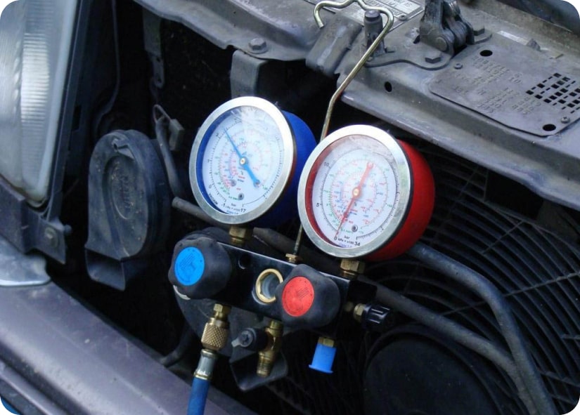
Код ошибки: P1
Ошибка датчика на входе
Нарушена герметичность датчика. Соединительный кабель замыкает
Проверить датчик на работоспособность, При необходимости заменить датчик
Код ошибки: P2
Ошибка датчика теплообменника
Датчик температуры некорректно подключен или поврежден
Проверить датчик на работоспособность, При необходимости заменить датчик

Код ошибки: P4
Дренажный поддон переполнен, случился обрыв поплавкового датчика CN4F
Возможно забит слив
Проверить дренаж на засоренность
Решение не помогло или нужно больше информации?
Проконсультируйтесь со специалистом или вызовите мастера!
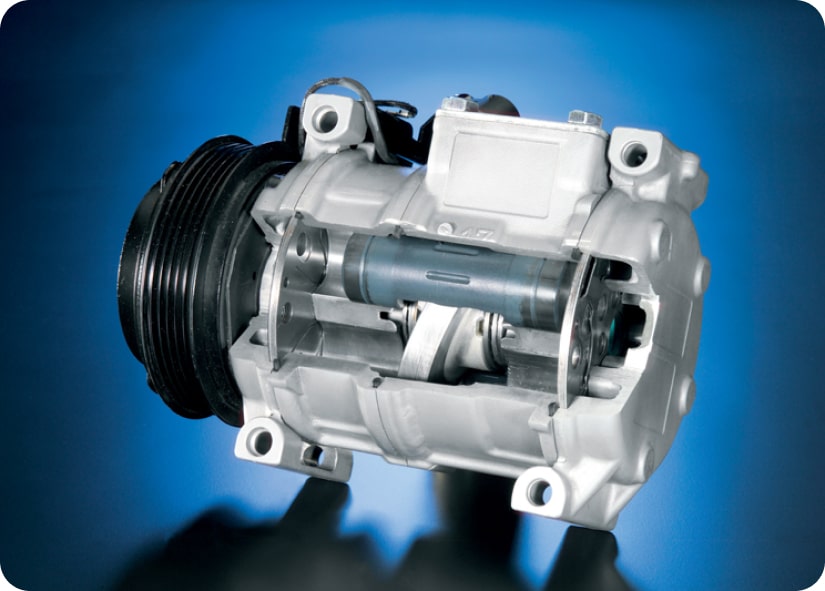
Код ошибки: P5
Ошибка дренажной помпы
Двигатель дренажа работает некорректно
Код ошибки: P6
Ошибка по обмерзанию или перегреву
Перегрев устройства Температура окружающей среды слишком высокая. Работа вентилятора осуществляется неверно. Загрязнение теплообменника
Код ошибки: P8
Температурный режим превысил норму
Сопротивление датчика превысило норму
Проверить температурный датчик на исправность
Код ошибки: P9
Ошибка по датчику теплообменника ТН2
Датчик и соединительный кабель замыкает
Код ошибки: PA
Принудительная остановка компрессора (из-за переполнения дренажной системы)

Код ошибки: E0/E3
Нет связи с пультом управления
Поменять батарейки пульта ду
Код ошибки: E1/E2
Неисправна плата пульта управления
Плата управления неисправна. Кабель связи неисправен. Рядом с кабелем проходит другой кабель и создает электромагнитные помехи
Код ошибки: E4/E5
Целостность датчиков температуры нарушено. Нарушение в напряжении сети
Проверить межблочное соединение. Поверить датчики температуры и давления.
Код ошибки: E9
Нет связи между внутренним и внешним блоком
Ошибка на внешнем блоке. Обрыв цепи.
Код ошибки: EE
Отсутствует межблочная связь между внутренним и внешним блоками
Сбой работы разъемов. Низкое напряжении на линии.
Код ошибки: U1/Ud
Высокое давление по датчику 63Н, или защита от перегрева
Возможно в системе избыток хладагента
Код ошибки: U2
Сработал датчик 49С, очень низкое давление нагнетания
Недостаток хладагента в системе
Код ошибки: U3/U4
Датчик температуры во внешнем блоке замкнул
Датчик температуры некорректно подключен или поврежден
Код ошибки: U5
Температура конденсатора не соответствует норме
Недостаток фреона в системе, загрязнении фильтров и испарителя
Код ошибки: U6
По токовой перезагрузки компрессор замкнул, неисправен силовой модуль
Причиной может служить загрязнение фильтров, крыльчатки вентиляторов, поверхность теплообменника.
Код ошибки: U7
Низкое давление нагнетания
Недостаток хладагента в системе
Код ошибки: U8
Двигатель вентилятора внешнего блока остановлен
Блокировка двигателя вентилятора, перегрузка или поврежденное соединение
Код ошибки: U9/UH
Неисправность токового датчика
Повышенное или пониженное напряжение питания,
Код ошибки: UF
Компрессор остановлен из-за токовой перегрузки
Код ошибки: UP
Остановка компрессора из-за перегрузки по току
Причиной может служить загрязнение фильтров, крыльчатки вентиляторов, поверхность теплообменника.
Код ошибки: Fb
Ошибка платы управления внутреннего блока
Поддержание оптимальной температуры в комнате необходимо для комфортных условий. Когда
кондиционер ломается, жаркая погода может испортить весь день, потому что заставит
чувствовать себя неприятно. Следует определить код ошибки кондиционеров и провести
дальнейшую диагностику, чтобы вернуть устройство к работе.
Как определяются коды ошибки кондиционеров Mitsubishi Electric
Для того чтобы считать коды ошибок кондиционеров Mitsubishi Electric, воспользуйтесь
инструкцией производителя, а затем расшифруйте код при помощи таблицы:
| P1 | Неисправность датчика температуры ТН3 |
| Р2 | Неисправность датчика, считывающего данные TH5-теплообменника |
| Р4 | Дренажный поддон наполнен выше нормы (также возможна неисправность датчика-поплавка CN4F) |
| Р5 | Неисправность помпы, установленной в дренажном отсеке |
| Р6 | Неправильное выполнение команды понижения или повышения температуры |
| Р8 | Неправильная температура установилась в теплообменнике |
| Р9 | Неисправность датчика, считывающего данные ТН2-теплообменника |
| РА | Компрессор был аварийно и принудительно остановлен |
| Е0 | Невозможна передача сигнала к пульту управления |
| Е1 | Кнопки на пульте управления неисправны |
| Е2 | Адреса внутренних систем дублированы |
| Е3 | Адрес наружного блока указан неправильно |
| Е4; Е5 | Приемник сигнала с пульта управления неисправен |
| Е6 | Есть замыкание в соединении внутреннего и внешнего блока |
| Е7 | Ошибка передачи данных в системе |
| Е8 | Обрыв цепи около датчика приема данных |
| Е9 | Не получается связаться с передатчиком |
| Е0 | Низкий заряд батареи пульта |
| ЕА | Неправильная установка электросети и соединений проводов |
| ЕВ | Защита электросети от перенапряжения |
| ЕС | Не получилось запустить работу системы по таймеру |
| Ed | Необходимо сбросить все до базовых настроек |
| ЕЕ | Невозможно передать данные на передатчик |
| EF | M-NET ошибка – неправильное соединение проводов |
| U1 | Датчик 63Н указывает на давление выше нормы (либо температуру выше нормы) |
| U1 | Фатальная ошибка |
| U2 | Датчик 49С говорит о низком давлении при заборе воздуха или низком уровне хладагента |
| U2 | Компрессор работает на высокой температуре |
| U3 | Варистор конденсатора неисправен |
| U4 | В электросети датчика температуры внешнего блока есть обрыв или короткое замыкание |
| U5 | Датчик температуры конденсатора сигнализирует о превышении нормы |
| U6 | Обнаружена токовая перегрузка электросети компрессора, устройство остановлено |
| U7 | Датчик 49С указывает на ошибку |
| U8 | Принудительная остановка моторчика вентилятора, установленного во внешнем блоке |
| U9; UH | Отклонение от нормы напряжения электрического тока, поступающего от сети, ошибка в показаниях датчика напряжения тока |
| UA | Ошибка пускового реле компрессора |
| UD | Компрессор перегрелся |
| UL | Низкое давление хладагента |
| UF | Слишком высокий уровень напряжения, остановка компрессора |
| UP | Перегрузка электросети, принудительная остановка компрессора |
| Fb | Ошибка системы программирования |
| F1 | Нет данных от датчика температуры ТН3 |
| F2 | Обрыв фазы на участке L3 |
| F3 | Неправильное соединение с внутренней платой управления – нет сигнала |
| F4 | Разомкнулся разъем |
| F7 | Нарушена последовательность в фазах шлейфа |
| F8 | Нестабильное напряжение сети |
| F9 | Нет сигнала в разъемах |
| FA | Обрыв фазы на участках L2 |
Ошибки кондиционеров Mitsubishi Electric на пульте ДУ
| Е0 | Не получается передать команду на кондиционер |
| Р1 | Данные о всасываемом воздухе считываются неправильно |
| Р2 | Неисправность трубочек |
| Р3 | Системная ошибка |
| Р4 | Нет данных от датчика Drain |
| Р5 | Утечка переполнения защиты механизма |
| Р6 | Неправильно проведено снижение или увеличение температуры |
| Р7 | Системная ошибка (формирование данных) |
| Р8 | Обрыв соединения |
LED лампы
| Статус операции | Проверка выдачи кода ошибки |
|---|---|
| LD1 | Компрессор |
| LD2 | Регулировка температуры |
| LD3 | Проведение операции 63Н3 |
| LD4 | Компрессор работает во время операции 63Н2 |
| LD5 | Включен вентилятор |
| LD6 | Работает четырехходовой клапан |
| LD7 | Перепускной клапан |
| LD8 | Работает нагреватель картера |
| Индикация светодиода | |
| Вспышка раз в 2 секунды | Неисправно питание конвертора, внешнее питание, термистор или система управления наружного блока |
| Две вспышки раз в 2 секунды | Защита от короткого замыкания |
| Три вспышки раз в 2 секунды | Защита от превышения нормальной температуры системы нагнетания |
| Четыре вспышки раз в 2 секунды | Защита от превышения нормальной температуры термистора |
| Пять вспышек раз в 2 секунды | Защита от превышения нормы давления в системе |
| Семь вспышек раз в 2 секунды | Защита от случайного старта системы |
| Восемь вспышек раз в 2 секунды | Защита ошибки в установке температуры |
| Одна вспышка | Снизилось напряжение в электросети |
| Три вспышки | Сработал режим размораживания |
| Четыре вспышки | Высокая температура системы нагнетания |
| Пять вспышек | Термистор наружный |
| Семь вспышек | Низкая температура системы нагнетания |
| Восемь вспышек | Конвертор защищается |
| Девять вспышек | Инвертор проверяется |