
-
Page 1
Original instructions PLUTO Safety-PLC Operating instructions Hardware English v11A 2TLC172001M0211_A… -
Page 2: Table Of Contents
Table of contents: General ……………………..4 Enclosure ……………………. 5 Electrical installation ………………….5 Inputs and outputs ………………….6 I.. Digital failsafe inputs ………………..12 IQ.. Digital failsafe inputs / Digital outputs (non failsafe) ……….13 4.2.1 Dynamic signals ………………….13 4.2.2 Current monitoring IQ16, IQ17 (Only A20) …………..
-
Page 3
Connection examples ………………… 35 Example of applications ………………..38 Pluto bus communication ………………..39 Bus cabling ……………………39 9.1.1 Cable length ……………………40 9.1.2 Connection of bus cable shield ………………40 9.1.3 Optional protection against conducted disturbances …………41 Response time over the bus ………………. 41 Identifier ……………………. -
Page 4: General
1 General Pluto is a programmable safety system intended for safety applications where it is not accepted that faults in the control system lead to loss of a safety function. To achieve this requirement the system is designed with integral redundancy and monitoring. Unlike ordinary PLC systems, Pluto utilizes two microprocessors, which both control and monitor each safety function for correct operation.
-
Page 5: Enclosure
2 Enclosure Pluto is constructed in an enclosure for snap mounting on a DIN-rail in control cabinets or other suitable enclosures. External wiring is connected via screw terminals. To make it easy and to avoid incorrect connection when a unit is exchanged, the connector blocks are detachable so that individual wires do not have to be disconnected.
-
Page 6: Inputs And Outputs
4 Inputs and outputs In order to be as flexible as possible Pluto offers various combinations of different I/O: s. There are also different families and types of PLUTO. Pictured below are the IO overviews for the various Pluto types. Transistor output, individual failsafe Inputs, individual failsafe…
-
Page 7
Transistor output, Inputs, individual failsafe individual failsafe Pluto bus 0-10V/4-20mA Pluto D20 0-24V IQ10 IQ11 IQ12 IQ13 IQ14 IQ15 IQ16 IQ17 0V +24V Identifier Power Failsafe inputs / Indication outputs (not failsafe) / Dynamic outputs Relay output, input individual failsafe I/O overview PLUTO D20 Inputs and outputs for Pluto D20 Terminal on Pluto… -
Page 8
Inputs, individual failsafe Inputs, individual failsafe Inputs, individual failsafe Digital/Analogue SR41 SR45 SR46 +24V Power Pluto B46, S46 supply Identifier IDFIX Safety outputs Pluto bus IQ10 IQ11 IQ12 IQ13 IQ14 IQ15 IQ16 IQ17 IQ20 IQ21 IQ22 IQ23 IQ24 IQ25 IQ26 IQ27 Failsafe inputs / Outputs (not failsafe) / Dynamic outputs 1) Not S46-6… -
Page 9
Digital inputs, individual failsafe Analogue inputs 0-10V/4-20mA Inputs, individual failsafe Inputs, individual failsafe Fast counter DI AI DI AI DI AI DI AI DI AI DI AI +24V Power supply Pluto D45 Identifier IDFIX Safety outputs Pluto bus CS (Shield) IQ10 IQ11 IQ12… -
Page 10
Inputs, individual failsafe Inputs, individual failsafe Inputs, individual failsafe AS-Interface Digital/Analogue ASi+ ASi- SR41 SR45 SR46 +24V Power supply Pluto B42 AS-i Identifier IDFIX Safety outputs Pluto bus (Shield) IQ10 IQ11 IQ12 IQ13 IQ14 IQ15 IQ16 IQ17 IQ20 IQ21 IQ22 IQ23 IQ24 IQ25… -
Page 11
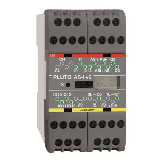
Power supply Inputs, individual failsafe CAN-bus AS-Interface Identifier input +24V ASI+ ASI- Pluto AS-i IQ10 IQ11 IQ12 IQ13 DI AI DI AI Failsafe inputs / Analogue inputs Safety outputs Outputs (not failsafe) / Dynamic outputs I/O overview PLUTO AS-i Inputs and outputs for Pluto AS-i Terminal on Pluto In-/Output name in software I/O type… -
Page 12: Digital Failsafe Inputs
Safe inputs Dynamic outp 24V, 1.5A 250VAC, 5A Non-safe outp IQ10 Pluto O2 Safety Output Module IQ11 +24V 0V Non-safe outp Power supply Dynamic outp 24V, 1.5A 250VAC, 5A Safe inputs I/O overview PLUTO O2 Inputs and outputs for Pluto O2 Terminal on Pluto In-/Output name in software I/O type…
-
Page 13: Dynamic Signals
IQ.. Digital failsafe inputs / Digital outputs (non failsafe) This type of IO-terminals provides 4 different functions. Each terminal is connected to both processors and may therefore be used as a failsafe input. Each terminal is also equipped with an output transistor giving the user the possibility to configure it as either a failsafe input or non failsafe output.
-
Page 14: Analogue Inputs
Analogue inputs 4.3.1 Analogue inputs 0-10V / 4-20mA (Pluto D20 and D45) Pluto D20 is equipped with 4, and Pluto D45 with 8, safe 4-20mA/0-10V analogue inputs. These (D20: IA0 – IA3, D45: IA0 – IA7) can be configured as either “ordinary” failsafe inputs, as analogue inputs 0-10V or as analogue inputs 4-20mA.
-
Page 15: Volt
4.3.1.2 0 Volt In general 0 or close to 0 volt/mA cannot be trusted as a true signal except when there is a dynamic behaviour in the application which makes it possible to evaluate the correctness. There are two reasons for this: 0 can be a consequence of an internal fault in Pluto.
-
Page 16: Connection Of Analogue Voltage Output Sensors (0-10V)
4.3.2.1 Connection of analogue voltage output sensors (0-10V) It is important that the 0V wire from the analogue sensor is connected directly to the terminal ”0V” on Pluto, and not to 0V somewhere else. Otherwise current in the 0V conductor may affect the measured analogue value.
-
Page 17: Counter Inputs Pluto D45
Counter inputs Pluto D45 For Pluto D45 the inputs IA0 – IA3 can be configured as counter inputs (pulse counting) which work for frequencies up to 14000 Hz. As counter inputs IA0 – IA3 can be used in two ways, Up counting or Up/Down counting.
-
Page 18: Up/Down Count
4.4.2 Up/Down count In order to determine the direction of a movement input IA0 and IA2 can be configured as Up/Down counters. When this is done the next input (IA1 or IA3) is automatically reserved for Up/Down counting. This means that for Up/Down counting IA0-IA1 are a pair and IA2-IA3 are another pair.
-
Page 19: Sensor Output Types
4.4.3 Sensor output types +24V +24V Push-pull / HTL sensor output. Open collector / PNP sensor output Typical for incremental encoders Typical for proximity sensors and photocells Incremental encoders with HTL output and other with push-pull output can be used at frequencies up to around 14 kHz.
-
Page 20: Speed Monitoring With One Sensor
Interruption in the cabling to a sensor will lead to that Pluto read 0-speed from that sensor. Such fault must therefore be detected in the application by using two independent sensors that are automatically cyclically checked with regard to that there is motion in the machine at least a couple of times per day.
-
Page 21: Possible Architectures, Achievable Safety Levels And Prerequisites
4.4.7 Possible architectures, achievable safety levels and prerequisites This table is an overview of safety levels for different applications. The achievable Cat / SIL / PL depends on the sensor which is used in the application and the detection capability of faults listed in IEC 61800-5-2, table D.16. Structure Usage Achievable…
-
Page 22: Failsafe Outputs
Failsafe outputs 4.5.1 Relay outputs Each potential free relay output is made individually “redundant” by the use of two series connected relay contacts controlled by each processor. A single output can be used to individually control a safety function, however the outputs cannot detect short circuits in e.g. connection cables.
-
Page 23: Test Pulses
4.5.2.1 Test pulses In order to make internal tests and to test against external short circuits the outputs Q2 and Q3 are cyclically switched off during 100..200 µs, so called test pulses. Principle for solid state safety outputs. Diagram showing output voltage with test pulses 4.5.2.1.1 Disabling of test pulses For Pluto A20 v2, B20 v2, S20 v2 and Pluto D20, the test pulses can be disabled via Pluto Manager.
-
Page 24: As-Interface Bus (As-I)
AS-Interface bus (AS-i) Only for Pluto AS-i and B42 AS-i As can be seen in the I/O overview Pluto AS-i has only 8 digital I/O but is equipped with connection for AS-i bus. AS-i is a standardised industrial bus where both power and data is transmitted via a two-wire cable.
-
Page 25: Reading Safety Slaves
4.6.2 Reading safety slaves The main intention with Pluto AS-i is to read and evaluate the safety slaves with its dual CPU. A standard slave can have 4 input variables which are read separately by the master. A safety slave has also 4 input variables, but physically only one single channel or dual channel input. The 4 input variables are used to send a safety code, unique for each slave.
-
Page 26: Modes Of Operation
Pluto as Safe Input This is the setting for a Pluto that is used as a safe input slave. A special function block, “PlutoAsSafeInput”, is needed for the PLC program. Configuration of the safe input and non- safe outputs are the same as for the ordinary “Safe input” slave. Pluto can handle up to 16 “PlutoAsSafeInput”…
-
Page 27: Connection Of Inputs
5 Connection of inputs Dynamic signals The IQ terminals can be configured as dynamic outputs, and be used for voltage supply of the input devices. If they are configured as dynamic, each of them generates a unique pulse train as shown in the diagram below. The system is intended for detection of different short circuits in external cabling, and dynamic monitoring of sensors.
-
Page 28: Connection Of In-/Outputs Iq
5.1.2 Connection of in-/outputs IQ.. The IO type IQ_ have some restrictions. If they are to be used as failsafe single channel inputs they must be configured as dynamic; A, A-inverse, B, B-inverse, C or C-inverse. For some two- channel devices also +24V can be used. Configured as dynamic output Dyn A, B or C The system does not accept…
-
Page 29: Connection Of Safety Devices
6 Connection of safety devices Dual channel systems The classic way of making a failsafe system is to use two-channel devices. The system offers various possibilities for connection of such devices. The figures below show solutions for connection of two channel devices. The first figure gives example of possible connections and the second shows the common connection of several dual channel safety devices.
-
Page 30: Single Channel Systems
Single channel systems Instead of using two-channel systems some applications can be made failsafe by using the principle of a dynamic single channel. By supplying electronic devices with dynamic signals a fault in the electronics will lead to a static on or off state at the input which will be detected immediately. By inverting the signal in or at the sensor, short circuits over the sensor are also detected.
-
Page 31: Monitoring Of External Short Circuit
Monitoring of external short circuit The system offers three main methods for avoiding that short circuit in input cabling leads to loss of the safety function. The drawing below illustrates the different methods by which emergency stop buttons can be connected. The first button has two NC contacts supplied by one dynamic signal and +24V.
-
Page 32: Safety Devices With Transistor Outputs
Safety devices with transistor outputs Certain safety devices on the market, i.e. light curtains, light beams, scanners etc., are designed with dual monitored safety 24V DC transistor outputs. These devices monitor the output circuits by making short interruptions in the output signals. Both channels can be connected to the system as static inputs.
-
Page 33: Two-Hand Control
Two-hand control Two-hand control devices can be realized in many ways depending on the contact configuration in the two-hand device and which Pluto inputs are used. Below are some examples of solutions. All of the examples shown fulfil the requirements for type IIIC according to EN 574.
-
Page 34: Illuminated Push Button Function
Illuminated push button function It is possible to connect both an indicator lamp and an input switch at the same time to IQ terminals, e.g. illuminated push button. A diode must be connected locally to the input device. The function is mainly intended for reset devices and reduces the number of IQ terminals used. Note that the output voltage is a square wave of 24 V amplitude and the effective voltage to the indicator is reduced to a mean value of 75%.
-
Page 35: Connection Of Outputs
7 Connection of outputs Below are examples of output connections that give different degrees of protection against short circuits. When and where they can be used depends on the kind of machine application (risk) and the electrical installation. Connection examples Output examples 1: Connection and monitoring of contactors.
-
Page 36
Output examples 2: Contact expansion with expansion relays and safety relay Monitoring Monitoring I_/IQ_ I_/IQ_ -24V +24V +24V (Minus) /IQ_ /IQ_ Test The examples give the same degree of safety and have the same advantages and disadvantages as output examples 1 and can be used for the same type of applications. Output examples 3: Short circuit protected Connection and monitoring of contactors with protection against short circuit, for applications with very high demands on safety integrity level. -
Page 37
Output example 4: Polarized safety relays Monitoring I_/IQ_ /IQ_ Test When using a safety relay for output expansion of output Q2 and Q3, the connection between the Pluto output and the safety relay is failsafe against short circuit from foreign +24V. This because it is operated by -24V and since the safety relay is polarized it cannot be switched on by +24V. -
Page 38: Example Of Applications
Example of applications 2TLC172001M0211_A…
-
Page 39: Pluto Bus Communication
Pluto bus communication Up to 32 Pluto units can be interconnected with CAN-bus. Communication is achieved by connecting a twisted pair cable to the CH and CL terminals. When this connection is made the Pluto units can read each other’s I/O. When the bus is connected each Pluto unit executes its own individual program and operates independently, however it can read other units I/O.
-
Page 40: Cable Length
9.1.1 Cable length The maximum cable length is depending on the bus speed. Data Trunk Distance Stub length Rate Units connected on a Stub must not have termination resistors fitted. Max single stub Accumulated stub length 100 kbit/s 600 m 25 m 120 m 125 kbit/s…
-
Page 41: Optional Protection Against Conducted Disturbances
9.1.3 Optional protection against conducted disturbances Conducted disturbances may cause problems with the Pluto bus communication. This problem might be solved by connecting a capacitor between 0V on Pluto Supply and earth. Please note that this connection is optional. It shall only be tried if there is a problem with the bus communication! IQ10 IQ11…
-
Page 42: Identifier
10 Identifier The identifier is an external component that can be connected to the “ID” and “0V” terminals. The circuit contains a unique ID-number that can be read by the system. In the PLC program the identifier number can be declared which connects the program so that it will only work together with the correct identifier.
-
Page 43
— The PLC program in IDFIX-PROG can be loaded into flash memory by pressing the K button in the same way as self programming over the CAN bus. This can be done when Pluto displays error message Er20 (No program loaded), Er24 (Erroneous PLC program) or Er31 (IDFIX-PROG program mismatch). -
Page 44: Programming
11 Programming The development of application programs (Pluto PLC program) is made with a standard Personal Computer using a specially developed software Pluto Manager. Communication between the PC and the Pluto is made via the PC Com Port or USB port. The link facilitates program down loading and monitoring of inputs, outputs, memory, timers, etc.
-
Page 45: Cleaning
12 Cleaning The front plate can be cleaned by a dry dust rag. The front plate can also be removed for cleaning or exchange. 13 Technical data Supply Nominal Voltage 24 V DC Tolerance +/-15% Max interruption 20 ms Recommended external fuse A20, B16, B20, S20, B22, D20, Pluto AS-i, O2: 6A B46, S46, D45, B42 AS-i: 10A Total current consumption…
-
Page 46
Safety output Q2, Q3: Solid state, -24V DC, 800mA Output voltage tolerance: Supply voltage -1.5V at 800mA Q0, Q1, (Q4, Q5): Relay, AC-12: 250 V / 1.5 A AC-15: 250 V / 1.5 A DC-12: 50 V / 1.5 A DC-13: 24 V / 1.5 A Pluto O2: Q0, Q1: 13-14, 23-24… -
Page 47
Indication: Input/Output LED’s Controlled by processor General Enclosure A20, B16, B20, S20, B22, D20, O2 and Pluto AS-i: 45 x 84 x 120 mm (w x h x d) B46, S46, D45 and B42 AS-i: 90 x 84 x 120 mm (w x h x d) Mounting DIN-Rail Response time of dynamic A or static input (+24V) -
Page 48
Safety parameters SIL according to EN 62061/IEC 61508 SIL 3 PL according to EN ISO 13849-1 PL e Category according to EN ISO 13849-1 according to EN ISO 13849-1 High CCF according to EN ISO 13849-1 Meets the requirements HFT (Hardware fault tolerance) >99% for the single channel parts SFF (Safe failure fraction) >90% for the double channel parts… -
Page 49: Connection Of Sensors
13.1 Connection of sensors Maximum number of sensors that can be connected in series with 100m cable: Eden Spot 35 Spot 10 Tina Maximum cable length, without sensors, for inputs using dynamic signals (depending on capacitance): Example 10×0.75 mm² = approx. 1000 meter 2TLC172001M0211_A…
-
Page 50: Appendix — Message And Fault Code List
14 Appendix — Message and fault code list Note: Reboot can either be made from PC computer or by power off-on. Status messages Description Power up Run mode (nn = station number) Program load mode state. Flashing ”Lo”, ready for self programming (program found in other unit). Program execution stopped from PC computer or not started after program download.
-
Page 51
I/O faults Fault and possible reason. Reset action Er40* Error safety output Q2 or Q3. “K” button Q2, Q3 connected together or to other negative voltage. Q2, Q3 has too high capacitive load. Er41* Error output Q2 or Q3. Overload or connected to foreign “K”… -
Page 52
AS-i Fault and possible reason. Reset action AE 01 ASi power missing. Automatically reset AE 02 No connection with ASi master (in Monitor mode). Automatically reset AE 03 Safety code missing by code teaching. Teach AS-i safety codes AE 04 Wrong code table. -
Page 53
Pluto O2 — Indicators Pluto O2 has 6 LED indicators instead of display. These have the following function. Indicator Description – Input on Flash – Two channel fault, generated by function block. Or power on input and program not loaded. –… -
Page 54
EC declaration of conformity ABB AB declare under our sole responsibility that the safety Jokab Safety components of ABB manufacture, with type designations Kanalvägen 17 and safety functions as listed below, are in conformity with SE-183 30 Täby the Directives… -
Page 55
ABB Ltd. Tel: +34 93 4842121 Produtos de Baixa Tensão Tel +353 1 4057 381 Fax: +34 93 484 21 90 ABB Atende: 0800 014 9111 Fax: +353 1 4057 312 Web: www.abb.es Fax: +55 11 3688-9977 Mobile: +353 86 2532891 Web: www.abb.com.br…
Note: Reboot can either be made from PC computer or by power off-on.
Status messages
No:
Description
— —
Power up
N n
Run mode (nn = station number)
Lo
Program load mode state.
Flashing «Lo», ready for self programming (program found in other unit).
HA
Program execution stopped from PC computer or not started after program download.
(SR11=7)
Can be started either from PC or by power off-on.
UE
Application specific user error, controlled by SR_PlutoDisplay in the PLC program.
User faults
No:
Fault and possible reason.
Er10*
Dynamic output short circuited to foreign voltage.
Er11*
IQ_ for illuminated push button function. Missing diode.
Er12*
Short circuit between two dynamic inputs.
Er13*
Static output Q10..17 (Q20..27) short circuited to 0V or
overloaded.
Er14*
Static output Q10..17 (Q20..27) short circuited to 24V.
Er15
Power supply below 18V.
Er16
Power supply above 30V.
Er17
Power supply below 15V. Critically low.
Er18
CAN-bus fault. (Short circuit, termination resistor, etc.)
Er19
Other unit with same station number on Can-bus.
Er20
PLC-program not loaded.
Er21
PLC-program CRC-error.
Er22
IDFIX problem. External IDFIX can not be read.
Er23
Unmatched ID. IDFIX doesn’t match declaration in
program.
Er24
Erroneous PLC-code. Invalid PLC-instructions.
Er25
For versions as B16 or B22. Non existing output used in
program.
Er26
Baud rate conflict. Unit programmed for other baud rate
than current bus baud rate.
Note that Pluto must be rebooted after change of
baudrate in the PLC program.
Er27
Wrong checksum for unit member in common program.
Er28
PLC program does not match the Pluto family.
Families: [A/B/S/D 20, 16, 22], [B/S/D 45, 46], [Pluto AS-
i, B42 AS-i]
Er29
Unsupported program version. The program contains
instructions only supported by later customer specific
operating systems. **(See below)
Er30
Unsupported function block used. **(See below)
Er31
IDFIX-PROG program mismatch.
*Combined with LED flashing for the affected I/O.
**Additional information can be retrieved via Pluto Manager.
Reset action
Automatically reset
Automatically reset
Automatically reset
Automatically reset,
«K» button
Automatically reset
Autom. 3 min or «K» button
Autom. 3 min or «K» button
Autom. 3 min or «K» button
Autom. 3 min or «K» button
Load of PLC program
Reload with valid PLC-program
Reboot (Replace IDFIX)
Exchange of identifiers or re-
declaration of identifier in
program.
Reload with valid PLC-program
Reprogramming or reboot
Reprogramming or reboot
Change to other type of Pluto
or change the program.
Update of operating system
Update of operating system
Load program to flash memory
with «K» button.
50
2TLC172001M0211_A
-
Contents
-
Table of Contents
-
Bookmarks
Quick Links
Original instructions
PLUTO
Safety-PLC
Operating instructions
Hardware
English v11A
2TLC172001M0211_A
Related Manuals for ABB PLUTO Safety-PLC
Summary of Contents for ABB PLUTO Safety-PLC
-
Page 1
Original instructions PLUTO Safety-PLC Operating instructions Hardware English v11A 2TLC172001M0211_A… -
Page 2: Table Of Contents
Table of contents: General ……………………..4 Enclosure ……………………. 5 Electrical installation ………………….5 Inputs and outputs ………………….6 I.. Digital failsafe inputs ………………..12 IQ.. Digital failsafe inputs / Digital outputs (non failsafe) ……….13 4.2.1 Dynamic signals ………………….13 4.2.2 Current monitoring IQ16, IQ17 (Only A20) …………..
-
Page 3
Connection examples ………………… 35 Example of applications ………………..38 Pluto bus communication ………………..39 Bus cabling ……………………39 9.1.1 Cable length ……………………40 9.1.2 Connection of bus cable shield ………………40 9.1.3 Optional protection against conducted disturbances …………41 Response time over the bus ………………. 41 Identifier ……………………. -
Page 4: General
1 General Pluto is a programmable safety system intended for safety applications where it is not accepted that faults in the control system lead to loss of a safety function. To achieve this requirement the system is designed with integral redundancy and monitoring. Unlike ordinary PLC systems, Pluto utilizes two microprocessors, which both control and monitor each safety function for correct operation.
-
Page 5: Enclosure
2 Enclosure Pluto is constructed in an enclosure for snap mounting on a DIN-rail in control cabinets or other suitable enclosures. External wiring is connected via screw terminals. To make it easy and to avoid incorrect connection when a unit is exchanged, the connector blocks are detachable so that individual wires do not have to be disconnected.
-
Page 6: Inputs And Outputs
4 Inputs and outputs In order to be as flexible as possible Pluto offers various combinations of different I/O: s. There are also different families and types of PLUTO. Pictured below are the IO overviews for the various Pluto types. Transistor output, individual failsafe Inputs, individual failsafe…
-
Page 7
Transistor output, Inputs, individual failsafe individual failsafe Pluto bus 0-10V/4-20mA Pluto D20 0-24V IQ10 IQ11 IQ12 IQ13 IQ14 IQ15 IQ16 IQ17 0V +24V Identifier Power Failsafe inputs / Indication outputs (not failsafe) / Dynamic outputs Relay output, input individual failsafe I/O overview PLUTO D20 Inputs and outputs for Pluto D20 Terminal on Pluto… -
Page 8
Inputs, individual failsafe Inputs, individual failsafe Inputs, individual failsafe Digital/Analogue SR41 SR45 SR46 +24V Power Pluto B46, S46 supply Identifier IDFIX Safety outputs Pluto bus IQ10 IQ11 IQ12 IQ13 IQ14 IQ15 IQ16 IQ17 IQ20 IQ21 IQ22 IQ23 IQ24 IQ25 IQ26 IQ27 Failsafe inputs / Outputs (not failsafe) / Dynamic outputs 1) Not S46-6… -
Page 9
Digital inputs, individual failsafe Analogue inputs 0-10V/4-20mA Inputs, individual failsafe Inputs, individual failsafe Fast counter DI AI DI AI DI AI DI AI DI AI DI AI +24V Power supply Pluto D45 Identifier IDFIX Safety outputs Pluto bus CS (Shield) IQ10 IQ11 IQ12… -
Page 10
Inputs, individual failsafe Inputs, individual failsafe Inputs, individual failsafe AS-Interface Digital/Analogue ASi+ ASi- SR41 SR45 SR46 +24V Power supply Pluto B42 AS-i Identifier IDFIX Safety outputs Pluto bus (Shield) IQ10 IQ11 IQ12 IQ13 IQ14 IQ15 IQ16 IQ17 IQ20 IQ21 IQ22 IQ23 IQ24 IQ25… -
Page 11
Power supply Inputs, individual failsafe CAN-bus AS-Interface Identifier input +24V ASI+ ASI- Pluto AS-i IQ10 IQ11 IQ12 IQ13 DI AI DI AI Failsafe inputs / Analogue inputs Safety outputs Outputs (not failsafe) / Dynamic outputs I/O overview PLUTO AS-i Inputs and outputs for Pluto AS-i Terminal on Pluto In-/Output name in software I/O type… -
Page 12: Digital Failsafe Inputs
Safe inputs Dynamic outp 24V, 1.5A 250VAC, 5A Non-safe outp IQ10 Pluto O2 Safety Output Module IQ11 +24V 0V Non-safe outp Power supply Dynamic outp 24V, 1.5A 250VAC, 5A Safe inputs I/O overview PLUTO O2 Inputs and outputs for Pluto O2 Terminal on Pluto In-/Output name in software I/O type…
-
Page 13: Dynamic Signals
IQ.. Digital failsafe inputs / Digital outputs (non failsafe) This type of IO-terminals provides 4 different functions. Each terminal is connected to both processors and may therefore be used as a failsafe input. Each terminal is also equipped with an output transistor giving the user the possibility to configure it as either a failsafe input or non failsafe output.
-
Page 14: Analogue Inputs
Analogue inputs 4.3.1 Analogue inputs 0-10V / 4-20mA (Pluto D20 and D45) Pluto D20 is equipped with 4, and Pluto D45 with 8, safe 4-20mA/0-10V analogue inputs. These (D20: IA0 – IA3, D45: IA0 – IA7) can be configured as either “ordinary” failsafe inputs, as analogue inputs 0-10V or as analogue inputs 4-20mA.
-
Page 15: Volt
4.3.1.2 0 Volt In general 0 or close to 0 volt/mA cannot be trusted as a true signal except when there is a dynamic behaviour in the application which makes it possible to evaluate the correctness. There are two reasons for this: 0 can be a consequence of an internal fault in Pluto.
-
Page 16: Connection Of Analogue Voltage Output Sensors (0-10V)
4.3.2.1 Connection of analogue voltage output sensors (0-10V) It is important that the 0V wire from the analogue sensor is connected directly to the terminal ”0V” on Pluto, and not to 0V somewhere else. Otherwise current in the 0V conductor may affect the measured analogue value.
-
Page 17: Counter Inputs Pluto D45
Counter inputs Pluto D45 For Pluto D45 the inputs IA0 – IA3 can be configured as counter inputs (pulse counting) which work for frequencies up to 14000 Hz. As counter inputs IA0 – IA3 can be used in two ways, Up counting or Up/Down counting.
-
Page 18: Up/Down Count
4.4.2 Up/Down count In order to determine the direction of a movement input IA0 and IA2 can be configured as Up/Down counters. When this is done the next input (IA1 or IA3) is automatically reserved for Up/Down counting. This means that for Up/Down counting IA0-IA1 are a pair and IA2-IA3 are another pair.
-
Page 19: Sensor Output Types
4.4.3 Sensor output types +24V +24V Push-pull / HTL sensor output. Open collector / PNP sensor output Typical for incremental encoders Typical for proximity sensors and photocells Incremental encoders with HTL output and other with push-pull output can be used at frequencies up to around 14 kHz.
-
Page 20: Speed Monitoring With One Sensor
Interruption in the cabling to a sensor will lead to that Pluto read 0-speed from that sensor. Such fault must therefore be detected in the application by using two independent sensors that are automatically cyclically checked with regard to that there is motion in the machine at least a couple of times per day.
-
Page 21: Possible Architectures, Achievable Safety Levels And Prerequisites
4.4.7 Possible architectures, achievable safety levels and prerequisites This table is an overview of safety levels for different applications. The achievable Cat / SIL / PL depends on the sensor which is used in the application and the detection capability of faults listed in IEC 61800-5-2, table D.16. Structure Usage Achievable…
-
Page 22: Failsafe Outputs
Failsafe outputs 4.5.1 Relay outputs Each potential free relay output is made individually “redundant” by the use of two series connected relay contacts controlled by each processor. A single output can be used to individually control a safety function, however the outputs cannot detect short circuits in e.g. connection cables.
-
Page 23: Test Pulses
4.5.2.1 Test pulses In order to make internal tests and to test against external short circuits the outputs Q2 and Q3 are cyclically switched off during 100..200 µs, so called test pulses. Principle for solid state safety outputs. Diagram showing output voltage with test pulses 4.5.2.1.1 Disabling of test pulses For Pluto A20 v2, B20 v2, S20 v2 and Pluto D20, the test pulses can be disabled via Pluto Manager.
-
Page 24: As-Interface Bus (As-I)
AS-Interface bus (AS-i) Only for Pluto AS-i and B42 AS-i As can be seen in the I/O overview Pluto AS-i has only 8 digital I/O but is equipped with connection for AS-i bus. AS-i is a standardised industrial bus where both power and data is transmitted via a two-wire cable.
-
Page 25: Reading Safety Slaves
4.6.2 Reading safety slaves The main intention with Pluto AS-i is to read and evaluate the safety slaves with its dual CPU. A standard slave can have 4 input variables which are read separately by the master. A safety slave has also 4 input variables, but physically only one single channel or dual channel input. The 4 input variables are used to send a safety code, unique for each slave.
-
Page 26: Modes Of Operation
Pluto as Safe Input This is the setting for a Pluto that is used as a safe input slave. A special function block, “PlutoAsSafeInput”, is needed for the PLC program. Configuration of the safe input and non- safe outputs are the same as for the ordinary “Safe input” slave. Pluto can handle up to 16 “PlutoAsSafeInput”…
-
Page 27: Connection Of Inputs
5 Connection of inputs Dynamic signals The IQ terminals can be configured as dynamic outputs, and be used for voltage supply of the input devices. If they are configured as dynamic, each of them generates a unique pulse train as shown in the diagram below. The system is intended for detection of different short circuits in external cabling, and dynamic monitoring of sensors.
-
Page 28: Connection Of In-/Outputs Iq
5.1.2 Connection of in-/outputs IQ.. The IO type IQ_ have some restrictions. If they are to be used as failsafe single channel inputs they must be configured as dynamic; A, A-inverse, B, B-inverse, C or C-inverse. For some two- channel devices also +24V can be used. Configured as dynamic output Dyn A, B or C The system does not accept…
-
Page 29: Connection Of Safety Devices
6 Connection of safety devices Dual channel systems The classic way of making a failsafe system is to use two-channel devices. The system offers various possibilities for connection of such devices. The figures below show solutions for connection of two channel devices. The first figure gives example of possible connections and the second shows the common connection of several dual channel safety devices.
-
Page 30: Single Channel Systems
Single channel systems Instead of using two-channel systems some applications can be made failsafe by using the principle of a dynamic single channel. By supplying electronic devices with dynamic signals a fault in the electronics will lead to a static on or off state at the input which will be detected immediately. By inverting the signal in or at the sensor, short circuits over the sensor are also detected.
-
Page 31: Monitoring Of External Short Circuit
Monitoring of external short circuit The system offers three main methods for avoiding that short circuit in input cabling leads to loss of the safety function. The drawing below illustrates the different methods by which emergency stop buttons can be connected. The first button has two NC contacts supplied by one dynamic signal and +24V.
-
Page 32: Safety Devices With Transistor Outputs
Safety devices with transistor outputs Certain safety devices on the market, i.e. light curtains, light beams, scanners etc., are designed with dual monitored safety 24V DC transistor outputs. These devices monitor the output circuits by making short interruptions in the output signals. Both channels can be connected to the system as static inputs.
-
Page 33: Two-Hand Control
Two-hand control Two-hand control devices can be realized in many ways depending on the contact configuration in the two-hand device and which Pluto inputs are used. Below are some examples of solutions. All of the examples shown fulfil the requirements for type IIIC according to EN 574.
-
Page 34: Illuminated Push Button Function
Illuminated push button function It is possible to connect both an indicator lamp and an input switch at the same time to IQ terminals, e.g. illuminated push button. A diode must be connected locally to the input device. The function is mainly intended for reset devices and reduces the number of IQ terminals used. Note that the output voltage is a square wave of 24 V amplitude and the effective voltage to the indicator is reduced to a mean value of 75%.
-
Page 35: Connection Of Outputs
7 Connection of outputs Below are examples of output connections that give different degrees of protection against short circuits. When and where they can be used depends on the kind of machine application (risk) and the electrical installation. Connection examples Output examples 1: Connection and monitoring of contactors.
-
Page 36
Output examples 2: Contact expansion with expansion relays and safety relay Monitoring Monitoring I_/IQ_ I_/IQ_ -24V +24V +24V (Minus) /IQ_ /IQ_ Test The examples give the same degree of safety and have the same advantages and disadvantages as output examples 1 and can be used for the same type of applications. Output examples 3: Short circuit protected Connection and monitoring of contactors with protection against short circuit, for applications with very high demands on safety integrity level. -
Page 37
Output example 4: Polarized safety relays Monitoring I_/IQ_ /IQ_ Test When using a safety relay for output expansion of output Q2 and Q3, the connection between the Pluto output and the safety relay is failsafe against short circuit from foreign +24V. This because it is operated by -24V and since the safety relay is polarized it cannot be switched on by +24V. -
Page 38: Example Of Applications
Example of applications 2TLC172001M0211_A…
-
Page 39: Pluto Bus Communication
Pluto bus communication Up to 32 Pluto units can be interconnected with CAN-bus. Communication is achieved by connecting a twisted pair cable to the CH and CL terminals. When this connection is made the Pluto units can read each other’s I/O. When the bus is connected each Pluto unit executes its own individual program and operates independently, however it can read other units I/O.
-
Page 40: Cable Length
9.1.1 Cable length The maximum cable length is depending on the bus speed. Data Trunk Distance Stub length Rate Units connected on a Stub must not have termination resistors fitted. Max single stub Accumulated stub length 100 kbit/s 600 m 25 m 120 m 125 kbit/s…
-
Page 41: Optional Protection Against Conducted Disturbances
9.1.3 Optional protection against conducted disturbances Conducted disturbances may cause problems with the Pluto bus communication. This problem might be solved by connecting a capacitor between 0V on Pluto Supply and earth. Please note that this connection is optional. It shall only be tried if there is a problem with the bus communication! IQ10 IQ11…
-
Page 42: Identifier
10 Identifier The identifier is an external component that can be connected to the “ID” and “0V” terminals. The circuit contains a unique ID-number that can be read by the system. In the PLC program the identifier number can be declared which connects the program so that it will only work together with the correct identifier.
-
Page 43
— The PLC program in IDFIX-PROG can be loaded into flash memory by pressing the K button in the same way as self programming over the CAN bus. This can be done when Pluto displays error message Er20 (No program loaded), Er24 (Erroneous PLC program) or Er31 (IDFIX-PROG program mismatch). -
Page 44: Programming
11 Programming The development of application programs (Pluto PLC program) is made with a standard Personal Computer using a specially developed software Pluto Manager. Communication between the PC and the Pluto is made via the PC Com Port or USB port. The link facilitates program down loading and monitoring of inputs, outputs, memory, timers, etc.
-
Page 45: Cleaning
12 Cleaning The front plate can be cleaned by a dry dust rag. The front plate can also be removed for cleaning or exchange. 13 Technical data Supply Nominal Voltage 24 V DC Tolerance +/-15% Max interruption 20 ms Recommended external fuse A20, B16, B20, S20, B22, D20, Pluto AS-i, O2: 6A B46, S46, D45, B42 AS-i: 10A Total current consumption…
-
Page 46
Safety output Q2, Q3: Solid state, -24V DC, 800mA Output voltage tolerance: Supply voltage -1.5V at 800mA Q0, Q1, (Q4, Q5): Relay, AC-12: 250 V / 1.5 A AC-15: 250 V / 1.5 A DC-12: 50 V / 1.5 A DC-13: 24 V / 1.5 A Pluto O2: Q0, Q1: 13-14, 23-24… -
Page 47
Indication: Input/Output LED’s Controlled by processor General Enclosure A20, B16, B20, S20, B22, D20, O2 and Pluto AS-i: 45 x 84 x 120 mm (w x h x d) B46, S46, D45 and B42 AS-i: 90 x 84 x 120 mm (w x h x d) Mounting DIN-Rail Response time of dynamic A or static input (+24V) -
Page 48
Safety parameters SIL according to EN 62061/IEC 61508 SIL 3 PL according to EN ISO 13849-1 PL e Category according to EN ISO 13849-1 according to EN ISO 13849-1 High CCF according to EN ISO 13849-1 Meets the requirements HFT (Hardware fault tolerance) >99% for the single channel parts SFF (Safe failure fraction) >90% for the double channel parts… -
Page 49: Connection Of Sensors
13.1 Connection of sensors Maximum number of sensors that can be connected in series with 100m cable: Eden Spot 35 Spot 10 Tina Maximum cable length, without sensors, for inputs using dynamic signals (depending on capacitance): Example 10×0.75 mm² = approx. 1000 meter 2TLC172001M0211_A…
-
Page 50: Appendix — Message And Fault Code List
14 Appendix — Message and fault code list Note: Reboot can either be made from PC computer or by power off-on. Status messages Description Power up Run mode (nn = station number) Program load mode state. Flashing ”Lo”, ready for self programming (program found in other unit). Program execution stopped from PC computer or not started after program download.
-
Page 51
I/O faults Fault and possible reason. Reset action Er40* Error safety output Q2 or Q3. “K” button Q2, Q3 connected together or to other negative voltage. Q2, Q3 has too high capacitive load. Er41* Error output Q2 or Q3. Overload or connected to foreign “K”… -
Page 52
AS-i Fault and possible reason. Reset action AE 01 ASi power missing. Automatically reset AE 02 No connection with ASi master (in Monitor mode). Automatically reset AE 03 Safety code missing by code teaching. Teach AS-i safety codes AE 04 Wrong code table. -
Page 53
Pluto O2 — Indicators Pluto O2 has 6 LED indicators instead of display. These have the following function. Indicator Description – Input on Flash – Two channel fault, generated by function block. Or power on input and program not loaded. –… -
Page 54
EC declaration of conformity ABB AB declare under our sole responsibility that the safety Jokab Safety components of ABB manufacture, with type designations Kanalvägen 17 and safety functions as listed below, are in conformity with SE-183 30 Täby the Directives… -
Page 55
ABB Ltd. Tel: +34 93 4842121 Produtos de Baixa Tensão Tel +353 1 4057 381 Fax: +34 93 484 21 90 ABB Atende: 0800 014 9111 Fax: +353 1 4057 312 Web: www.abb.es Fax: +55 11 3688-9977 Mobile: +353 86 2532891 Web: www.abb.com.br…
* Изображения служат только для ознакомления,
см. техническую документацию
от 5 шт. —
277 500 руб.
от 10 шт. —
262 840 руб.
Добавить в корзину 1 шт.
на сумму 292 100 руб.
Номенклатурный номер: 8069597748
Артикул: 2TLA020070R1800 Pluto S46 v2
Страна происхождения: ГЕРМАНИЯ
Бренд / Производитель: ABB

Описание
Automation & Control GearPLCs, HMIs & Industrial ComputingSafety Automation Controllers
Pluto from ABB is an «All-Master» safety PLC concept, which simplifies the design of safety systems and achieves the highest safety category 4 according to EN 954-1.
Технические параметры
| Contact Current Rating | 5.1 A |
| Contact Voltage Rating | 24 V dc |
| IP Rating | IP20, IP40 |
| Number of I/O | 46 |
| Number of Safety Inputs | 24 |
| Number of Safety Outputs | 16 |
| Range | Pluto |
| Safety Category | 4 EN 954-1, PLe/Cat.4 EN ISO 13849-1 |
| Series | S46 v2 |
| Supply Voltage | 24 V dc |
| Width | 84mm |
| Вес, г | 704 |
Техническая документация
Сроки доставки
Доставка в регион Курск
| Магазин «ЧИП и ДИП» | 19 июля1 | бесплатно |
| ПВЗ Boxberry | 17 июля1 | бесплатно |
| ПВЗ СДЭК | 18 июля1 | бесплатно |
| ПВЗ Л-Пост | 18 июля1 | бесплатно |
| ПВЗ 5Post | 19 июля1 | бесплатно |
| ТК DPD | 17 июля1 | бесплатно |
| ТК «Деловые линии» | 18 июля1 | бесплатно |
| Почта России | 26 июля1 | бесплатно |
| Курьер | 18 июля1 | 416 руб.2 |
| ПВЗ Яндекс Доставка | 19 июля1 | 99 руб.2 |
Цена и наличие в магазинах
| ул. Карла Маркса, 68, ТЦ «Мега Гринн», 1 этаж | нет в наличии |
Step 1 – Solve Pluto S20 Error Codes
Is Pluto S20 Error Codes appearing? Would you like to safely and quickly eliminate pluto b20 manual which additionally can lead to a blue screen of death?
When you manually edit your Windows Registry trying to take away the invalid pluto s20 v2 keys you’re taking a authentic chance. Unless you’ve got been adequately trained and experienced you’re in danger of disabling your computer system from working at all. You could bring about irreversible injury to your whole operating system. As very little as just 1 misplaced comma can preserve your Pc from even booting every one of the way by!
Troubleshooting abb pluto s20 Windows XP, Vista, 7, 8 & 10
Simply because this chance is so higher, we hugely suggest that you make use of a trusted registry cleaner plan like CCleaner (Microsoft Gold Partner Licensed). This system will scan and then fix any Pluto S20 Error Codes complications.
Registry cleaners automate the entire procedure of finding invalid registry entries and missing file references (including the Codes error) likewise as any broken hyperlinks inside of your registry.
Issue with pluto b20 manual
Backups are made immediately prior to each and every scan providing you with the choice of undoing any changes with just one click. This protects you against doable damaging your pc. Another advantage to these registry cleaners is that repaired registry errors will strengthen the speed and performance of one’s procedure drastically.
Cautionary Note: Yet again, for those who are not an state-of-the-art consumer it’s very encouraged that you simply refrain from editing your Windows Registry manually. If you make even the smallest error within the Registry Editor it can result in you some serious issues that may even call for a brand new set up of Windows. Not all difficulties attributable to incorrect Registry Editor use are solvable.
Fixed: pluto manager manual
Symptoms of Pluto S20 Error Codes
“Pluto S20 Error Codes” appears and crashes the energetic method window.
Your Personal computer routinely crashes with Pluto S20 Error Codes when running the exact same system.
“Pluto S20 Error Codes” is shown.
Windows operates sluggishly and responds little by little to mouse or keyboard input.
Your computer periodically “freezes” for the number of seconds in a time.
Will cause of Pluto S20 Error Codes
Corrupt obtain or incomplete set up of Windows Operating System software program.
Corruption in Windows registry from a new Windows Operating System-related application adjust (install or uninstall).
Virus or malware infection which has corrupted Windows method documents or Windows Operating System-related application data files.
Another method maliciously or mistakenly deleted Windows Operating System-related files.
Mistakes this sort of as “Pluto S20 Error Codes” can be brought about by several different elements, so it really is important that you troubleshoot every of the achievable brings about to forestall it from recurring.
Simply click the beginning button.
Variety “command” inside the lookup box… Will not hit ENTER nonetheless!
Although keeping CTRL-Shift in your keyboard, hit ENTER.
You’re going to be prompted that has a authorization dialog box.
Click on Of course.
A black box will open having a blinking cursor.
Variety “regedit” and hit ENTER.
Within the Registry Editor, choose the pluto s20 v2 connected key (eg. Windows Operating System) you wish to back again up.
Within the File menu, choose Export.
Inside the Preserve In list, pick out the folder in which you wish to save the Windows Operating System backup key.
Inside the File Title box, sort a reputation for the backup file, these types of as “Windows Operating System Backup”.
From the Export Vary box, ensure that “Selected branch” is selected.
Click on Help you save.
The file is then saved by using a .reg file extension.
You now use a backup within your abb pluto s20 related registry entry.
Solution to your pluto manager software problem
There are actually some manual registry editing measures that can not be talked about in this article due to the high chance involved for your laptop or computer method. If you want to understand more then check out the links below.
Additional Measures:
One. Conduct a Thorough Malware Scan
There’s a probability the Codes Pluto Error S20 error is relevant to some variety of walware infection. These infections are malicious and ready to corrupt or damage and possibly even delete your ActiveX Control Error files. Also, it’s attainable that your Pluto S20 Error Codes is actually connected to some element of that malicious plan itself.
2. Clean jokab safety pluto b20 manual Disk Cleanup
The a lot more you employ your computer the extra it accumulates junk files. This comes from surfing, downloading packages, and any sort of usual computer system use. When you don’t clean the junk out occasionally and keep your program clean, it could turn into clogged and respond slowly. That is when you can encounter an S20 error because of possible conflicts or from overloading your hard drive.
Once you clean up these types of files using Disk Cleanup it could not just remedy Pluto S20 Error Codes, but could also create a dramatic change in the computer’s efficiency.
Tip: While ‘Disk Cleanup’ is definitely an excellent built-in tool, it even now will not completely clean up Pluto S20 discovered on your PC. There are numerous programs like Chrome, Firefox, Microsoft Office and more, that cannot be cleaned with ‘Disk Cleanup’.
Since the Disk Cleanup on Windows has its shortcomings it is extremely encouraged that you use a specialized sort of challenging drive cleanup and privacy safety application like CCleaner. This system can clean up your full pc. If you run this plan after each day (it could be set up to run instantly) you are able to be assured that your Pc is generally clean, often operating speedy, and always absolutely free of any S20 error associated with your temporary files.
How Disk Cleanup can help pluto safety plc
1. Click your ‘Start’ Button.
2. Style ‘Command’ into your search box. (no ‘enter’ yet)
3. When holding down in your ‘CTRL-SHIFT’ important go ahead and hit ‘Enter’.
4. You will see a ‘permission dialogue’ box.
5. Click ‘Yes’
6. You will see a black box open up plus a blinking cursor.
7. Variety in ‘cleanmgr’. Hit ‘Enter’.
8. Now Disk Cleanup will start calculating the amount of occupied disk space you will be able to reclaim.
9. Now a ‘Disk Cleanup dialogue box’ seems. There will be a series of checkboxes for you personally to pick. Generally it will likely be the ‘Temporary Files’ that consider up the vast majority of your disk area.
10. Verify the boxes that you want cleaned. Click ‘OK’.
How to repair pluto b46 v2
3. System Restore can also be a worthwhile device if you ever get stuck and just desire to get back to a time when your computer system was working ideal. It will work without affecting your pics, paperwork, or other crucial information. You can discover this option with your User interface.
Pluto S20
Manufacturer
Device
Operating System
Pluto S20 Error Codes
4.5 out of
5
based on
30 ratings.