
Betrieb
Beim Einschalten der Versorgungsspannung
übernimmt das Sicherheitssystem
PNOZmulti die Konfiguration aus der
Chipkarte. In der dafür benötigten Zeit
leuchten am Basisgerät die LEDs «POWER»,
«DIAG», «FAULT», «IFAULT» und «OFAULT».
Das Sicherheitssystem PNOZmulti ist
betriebsbereit, wenn am Basisgerät die
LEDs «POWER» und «RUN» dauerhaft
leuchten.
Fehleranzeige
LED aus
LED leuchtet
LED blinkt
Basis
Operation
When the supply voltage is switched on, the
PNOZmulti safety system copies the
configuration from the chip card. While this is
happening, the «POWER», «DIAG», «FAULT»,
«IFAULT» and «OFAULT» LEDs will light up
on the base module.
The PNOZmulti safety system is ready for
operation when the «POWER» and «RUN»
LEDs on the base module are continuously
lit.
Fault indicator
LED off
LED on
LED flashes
Exp.
Fehler
Das bestehende Anwender-
programm wurde gelöscht.
externer Fehler am Basisgerät,
der zum sicheren Zustand
führt, z. B. Abschlussstecker
nicht angeschlossen
externer Fehler, der zum
sicheren Zustand führt, z. B.
Querschluss oder Fehler an
Schaltmatteneingang
externer Fehler an den
Ausgängen des Basisgeräts,
z. B. Querschluss, der zum
sicheren Zustand führt
externer Fehler, der zum si-
cheren Zustand führt, z. B.
Querschluss
externer Fehler am Ausgang
interner Fehler am Basisgerät
interner Fehler am Basisgerät
interner Fehler am Basisgerät
interner Fehler am
Erweiterungsmodul
Basisgerät im STOP-Zustand
externer Fehler an den
Eingängen des Basisgeräts; der
Fehler führt nicht zum sicheren
Zustand, z. B. teilbetätigt
externer Fehler an den
Ausgängen des Basisgeräts; der
Fehler führt nicht zum sicheren
Zustand, z. B. Rückführeingang
defekt
externer Fehler an den
Eingängen; der Fehler führt
nicht zum sicheren Zustand,
z. B. teilbetätigt; Rückführein-
gang defekt
Das Feldbusmodul wurde nicht
erkannt.
Fehler an Kaskadiereingang;
Gerät bleibt im RUN-Zustand
Fehler an Kaskadierausgang;
Gerät bleibt im RUN-Zustand
Fault
The existing user program has
been deleted.
External fault on the base
module, leading to a safe
condition, e. g. terminator not
connected
External error leading to a safe
condition, e.g. short across the
contacts or error at safety mat
input
External fault on the outputs of
the base module, e. g. short
across the contacts, leading to
a safe condition
External fault leading to a safe
condition, e. g. short across
the contacts
External fault at the output
Internal fault on the base
module
Internal fault on the base
module
Internal fault on the base
module
Internal fault on the expansion
module
Base module in STOP
condition
External fault at the inputs of
the base module, which does
not lead to a safe condition,
e. g.partially operated
External fault at the outputs of
the base module, which does
not lead to a safe condition,
e. g. feedback input defective
External fault at the inputs,
which does not lead to a safe
condition, e. g. partially
operated; feedback input
defective
The fieldbus module was not
recognised.
Fault at cascading input; unit
remains in RUN condition
Fault at cascading output; unit
remains in RUN condition
— 7 —
Работа
Когда напряжение питания подано, система
безопасности PNOZmulti копирует
конфигурацию из карты памяти. Пока это
происходит, горят индикаторы «POWER»,
«DIAG», «FAULT», «IFAULT» и «OFAULT» на
базовом блоке.
Система безопасности PNOZmulti готова к
работе когда индикаторы «POWER» и «RUN»
на базовом блоке горят постоянно.
Индикаторы ошибки
Индикатор выключен
Индикатор включен
Индикатор мигает
Ошибка
Имевшаяся программа
пользователя была удалена.
Внешняя ошибка на базовом
блоке, переход в безопасный
режим, напр. не подключен
терминатор.
Внешняя ошибка приведшая к
переходу в безопасный режим.
Напр. короткое замыкание меж-
ду контактами или ошибка на
входе площадки безопасности.
Внешняя ошибка на выходах
базового блока, напр. короткое
замыкание контактов повлек-
шее переход в безопасный
режим.
Внешняя ошибка приведшая к
переходу в безопасный режим.
Напр. короткое замыкание
между контактами.
Внешняя ошибка на выходах.
Внутренняя ошибка базового
блока.
Внутренняя ошибка базового
блока.
Внутренняя ошибка базового
блока.
Внутренняя ошибка в модуле
расширения.
Базовый блок в режиме СТОП
Внешняя ошибка на входах
базового блока не вызвавшая
переход в безопасный режим,
напр. частичное
функционирование.
Внешняя ошибка на выходах
базового блока не вызвавшая
переход в безопасный режим,
напр. ошибка обратной связи
входа.
Внешняя ошибка на входах, не
вызывающая переход в
безопасный режим. Напр.
частичное функционирование
или ошибка обратной связи
входа.
Модуль полевой шины не
опознан.
Ошибка входа
каскадирования, блок остается
в рабочем режиме
Ошибка выхода
каскадирования, блок остается
в рабочем режиме
Программа пользователя на микропроцессорной карте должна быть идентична программе пользователя во внутренней памяти базового блока PNOZmulti. Базовый блок PNOZmulti осуществляет проверку каждый раз при запуске. Если пользовательские программы отличаются, светодиод отказа загорается красным светом. Чтобы скопировать пользовательскую программу с микропроцессорной карты, необходимо выполнить следующие действия.
PNOZ m0p / m1p / m2p / m3p:
- Отключить PNOZmulti от источника напряжения.
- Вставить в устройство микропроцессорную карту, на которую записана новая пользовательская программа.
- Вставить перемычку между выводом OA0 и вводом i19.
- Подключить питающее напряжение.
- Светодиод DIAG заморгает желтым.
- Отключить питающее напряжение.
- Извлечь перемычку между выводом OA0 и вводом i19.
- Снова подать питающее напряжение.
- Выполняется запуск PNOZmulti с новой программой
PNOZmulti mini и PNOZmulti 2:
- Отключить PNOZmulti от источника напряжения.
- Вставить в устройство микропроцессорную карту, на которую записана новая пользовательская программа.
- Подключить питающее напряжение.
- Если на дисплее отображается имя проекта и «Принять?», удерживайте поворотный переключатель на протяжении 5 секунд и затем отпустите.
- Выполняется запуск PNOZmulti с новой программой
Specifications:1525/1525178-pnoz_m0p.pdf file (27 May 2023) |
Accompanying Data:
Pilz PNOZ m0p Control Unit, Industrial Electrical PDF Operating Instructions Manual (Updated: Saturday 27th of May 2023 07:13:43 AM)
Rating: 4.7 (rated by 47 users)
Compatible devices: PNOZ mi1p, PIT m3.2p, PNOZ mc5.1p, PNOZ mc1p, PNOZ m1p, PSEN ma1.4n-51, PNOZ mo3p, PNOZ mo2p.
Recommended Documentation:
Text of Operating Instructions Manual
(Ocr-Read Version Summary of Contents, UPD: 27 May 2023)
-
1, — 1 — Das Basisgerät PNOZ m0p/ PNOZ m1p Das Basisgerät PNOZ m0p/PNOZ m1p (coated version) des modularen Sicher- heitssystems PNOZmulti dient dem sicherheitsgerichteten Unterbrechen von Sicherheitsstromkreisen. Das Gerät ist bestimmt für den Einsatz in: • NOT-AUS-Einrichtungen • Sicherheitsstromkreisen nach VDE 0113 Teil 1, 11/98 und EN 60204-1, 12/97 (z. B. bei beweglichen Ver…
-
2, Pilz PNOZ m0p — 2 — Gerätebeschreibung Sicherheitseigenschaften: Das Basisgerät erfüllt folgende Sicher- heitsanforderungen: • Die Schaltung ist redundant mit Selbst- überwachung aufgebaut. • Die Sicherheitseinrichtung bleibt auch bei Ausfall eines Bauteils wirksam. • Die Sicherheitsausgänge werden durch einen Abschalttest periodisch geprüft. • Die Relaiskontakte erfüllen die Anforde- run…
-
3, Pilz PNOZ m0p — 3 — µController µController 0 V T0 T1 T2 T3 Taktausgänge Test pulse outputs Sorties impulsionnelles Halbleiterausgänge, Hilfsausgang, Versorgungsanschlüsse Semiconductor outputs, auxiliary output, supply connections Sorties statiques, sorties information, bornes d’alimentation 13 14 23 24 I19 A1 Eingänge Inputs Entrées Interface Diagnosemodul diagnostic module module de …
-
4, — 4 — Basisgerät ohne Erweiterungsmodule montieren Stecken Sie den Abschlussstecker auf die mit «Termination/Link» gekennzeichnete Seite des Basisgeräts. Fig. 3: Basisgerät montieren Installing the base module Monter l’appareil de base Abschlussstecker Terminator Fiche de terminaison Basisgerät und Erweiterungsmodule verbinden (nur PNOZ m1p, PNOZ m1p …
-
5, — 5 — Sicherheitssystem inbetriebnehmen Inbetriebnahme vorbereiten: Beachten Sie bei der Vorbereitung der Inbetriebnahme: Achtung! Die steckbaren Anschlussklemmen der Relaisaus- gänge, die Netzspannung führen, nur im spannungslosen Zustand ziehen und stecken. • Das Sicherheitssystem und die Eingangs- kreise müssen immer aus einem Netzteil versorgt werden. Das Netzt…
-
6, Pilz PNOZ m0p — 6 — • Projekt von Chipkarte laden: Wichtig! Die Kontaktierung des Chips ist nur gewährleistet, wenn die Kontaktfläche sauber und unbeschä- digt ist. Schützen Sie deshalb die Kontaktfläche des Chips vor • Verunreinigung • Berührung • mechanischer Einwirkung wie z. B. Kratzern — Schieben Sie die Chipkarte mit dem aktuellen Projekt in den Chipkarten- schacht d…
-
7, — 7 — Fehler Das bestehende Anwender- programm wurde gelöscht. externer Fehler am Basisgerät, der zum sicheren Zustand führt, z. B. Abschlussstecker nicht angeschlossen externer Fehler, der zum sicheren Zustand führt, z. B. Querschluss externer Fehler an den Ausgängen des Basisgeräts, z. B. Querschluss, der zum sicheren Zustand führt externer Fehler, der zum sicheren Zustand f�…
-
8, Pilz PNOZ m0p — 8 — Technische Daten Elektrische Daten Versorgungsspannung (U B ) Spannungstoleranz (U B ) Restwelligkeit (U B ) Leistungsaufnahme bei U B ohne Last pro Erweiterungsmodul Statusanzeige Zeiten Einschaltverzögerung (nach Anlegen von U B ) Gleichzeitigkeit Kanal 1/2/3 Zweihandkreis Überbrückung von Spannungseinbrüchen Eingänge Anzahl Max.Anzahl der stromführenden Eingänge im Bereich der m…
-
9, Pilz PNOZ m0p — 9 — Hilfsausgänge Anzahl Spannung und Strom Galvanische Trennung Kurzschlussschutz Reststrom bei «0» Signalpegel bei «1» Umweltdaten Luft- und Kriechstrecken Klimabeanspruchung EMV Schwingungen nach Frequenz Amplitude Umgebungstemperatur PNOZ m1p PNOZ m1p coated version Lagertemperatur Mechanische Daten Schutzart Einbauraum (z. B. Scha…
-
10, Pilz PNOZ m0p — 10 — I0 I1 I2 I3 I4 I5 I6 I7 I8 I9 I10 I11 I12 I13 I14 I15 I16 I17 I18 I19 A1 A1 A2 A2 CI+ CI- CO- CO+ T0 T1 T2 T3 O0 O1 O2 O3 OA0 24V 24V 0V 0V 13 14 23 24 K1 K2 S1 K2 K1 S2 S3 L+ L- Anschlußbeispiel: zweikanalige NOT-AUS-und Schutztür- Beschaltung, überwachter Start (I17), Rückführkreis (I14) Connection example: Dual-channel E-STOP and safety gate w…
-
11, Pilz PNOZ m0p — 11 — CHIP-Card 94 (3.70″) 121 (4.76″) 135 (5.31″) 4GB Dimensions in mm («) 4F Dimensions en mm («)4D Abmessungen in mm («) 4GB Connector pin assignment 4F Affectation des raccords4D Anschlußbelegung
… -
12, — 12 — 20 878-06, 2005-08 Printed in Germany A Pilz Ges.m.b.H., ✆ 01 7986263-0, Fax: 01 7986264, E-Mail: [email protected] AUS Pilz Australia, ✆ 03 95446300, Fax: 03 95446311, E-Mail: [email protected] B L Pilz Belgium, ✆ 09 3217570, Fax: 09 3217571, E-Mail: [email protected] BR Pilz do Brasil, ✆ 11 4337-1241, Fax: 11 4337-1242, E-Mail: [email protected] CH P…
-
Pilz PNOZ m0p User Manual
-
Pilz PNOZ m0p User Guide
-
Pilz PNOZ m0p PDF Manual
-
Pilz PNOZ m0p Owner’s Manuals
Pilz PNOZ m0p Recommended Instructions:
PDW-U1, OFFICE X12, W6441, Hood Liner, 42HP66 — 42″ Plasma TV, CA 120


-
Comeval
MAXOMATIC Series
IOM — SELF-ACTING DIAPHRAGM VALVES MAXOMATIC VMXBERL24C ©COMEVAL VALVE SYSTEMS Technical Dept. Ref. IOM-SELF-ACTING DIAPHRAGM VALVES, MAXOMATIC VMXBXERL24C-Ed.15/05Comeval Valve Systems reserves the right to alter any technical data contained in this Manual without prior notice. Regularly updated data on www.comeval.esINSTALLATION, OPERATINGAND MAINTENANCE MANU …
MAXOMATIC Series 9
-
Advantech
PCM-3718 Series
(217) 352-9330 | [email protected] | artisantg.com-~ ARTISAN® ~I TECHNOLOGY GROUP Your definitive source for quality pre-owned equipment. Artisan Technology Group Full-service, independent repair center with experienced engineers and technicians on staff. We buy your excess, underutilized, and idle equipment along with credit for buybacks and trade-ins. Custom engi …
PCM-3718 Series 82
-
Renesas
RX Series
16 User’s Manual 32 All information contained in these materials, including products and product specifications, represents information on the product at the time of publication and is subject to change by Renesas Electronics Corporation without notice. Please review the latest information published by Renesas Electronics Corporation through various …
RX Series 28
-
Siemens
Simatic S7-300
Connection of the SINAMICS S120 to the Technology CPU __________________________________________________________________________________________________________________ SIMATIC S7-300 Connection of the SINAMICS S120 to the Technology CPU Product Information 09/2011 A5E00480378-04 Definitions and warnings 1 SINAMICS S120 automation components 2 Commissioning 3 Basic functions 4 Expe …
Simatic S7-300 208
-
Aeroflex
3030 Series
Artisan Technology Group is your source for quality new and certied-used/pre-owned equipment• FAST SHIPPING AND DELIVERY• TENS OF THOUSANDS OF IN-STOCK ITEMS• EQUIPMENT DEMOS• HUNDREDS OF MANUFACTURERS SUPPORTED• LEASING/MONTHLY RENTALS• ITAR CERTIFIED SECURE ASSET SOLUTIONSSERVICE CENTER REPAIRSExperienced engineers and technic …
3030 Series 91
Popular Right Now:
Operating Impressions, Questions and Answers:

Operating Manual — No. 1002053-EN-03
PNOZmulti Modular Safety System
PNOZ m0p
_Name_Bookmark2_
_Name_Bookmark2_
-
Contents
-
Table of Contents
-
Bookmarks
Quick Links
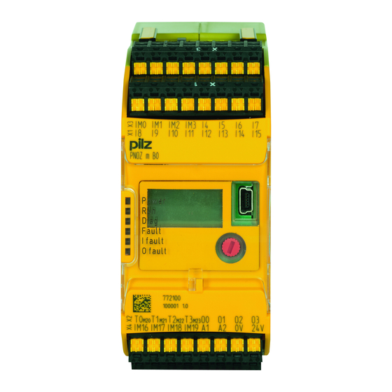
PNOZ m B0
}
Configurable, safe small controllers PNOZmulti 2
Operating Manual-1002660-EN-07
Related Manuals for Pilz PNOZ m B0
Summary of Contents for Pilz PNOZ m B0
-
Page 1
PNOZ m B0 Configurable, safe small controllers PNOZmulti 2 Operating Manual-1002660-EN-07… -
Page 2
Preface This document is the original document. All rights to this documentation are reserved by Pilz GmbH & Co. KG. Copies may be made for the user’s internal purposes. Suggestions and comments for improving this documenta- tion will be gratefully received. -
Page 3: Table Of Contents
Section 6 Commissioning General wiring guidelines Commissioning the control system 6.2.1 Connection 6.2.2 Load project from chip card 6.2.3 Load project via USB port Function test during commissioning Using the chip card Connection example Operating Manual PNOZ m B0 1002660-EN-07…
-
Page 4
Maximum capacitive load C (μF) with load current I (A) at the semicon- ductor outputs Maximum permitted total current of the semiconductor outputs Maximum permitted humidity 9.3.1 Max. relative humidity, operation 9.3.2 Max. relative humidity, storage Section 10 Order reference 10.1 Product 10.2 Accessories Operating Manual PNOZ m B0 1002660-EN-07… -
Page 5: Operating Manual Pnoz M B0
Introduction Introduction Validity of documentation This documentation is valid for the product PNOZ m B0. It is valid until new documentation is published. This operating manual explains the function and operation, describes the installation and provides guidelines on how to connect the product.
-
Page 6
Introduction INFORMATION This gives advice on applications and provides information on special fea- tures. Operating Manual PNOZ m B0 1002660-EN-07… -
Page 7: Overview
Base unit PNOZ m B0 Terminator Documentation on data medium Unit features Application of the product PNOZ m B0: Base unit of the configurable control system PNOZmulti 2 The product has the following features: Can be configured in the PNOZmulti Configurator…
-
Page 8: Chip Card
To be able to use the product you will need a chip card. Chip cards are available with memories of 8 kByte and 32 kByte. For large-scale projects we recommend the 32 kByte chip card (see Technical Catalogue: Accessories chapter). Operating Manual PNOZ m B0 1002660-EN-07…
-
Page 9: Front View
Configurable test pulse/auxiliary outputs T0M20 … T3M23 Semiconductor outputs O0 … O3 Configurable inputs/outputs IM0 – IM3 Inputs I4 … I7 Configurable inputs/outputs IM16 – IM19 Supply connections LEDs: DIAG FAULT I FAULT O FAULT Operating Manual PNOZ m B0 1002660-EN-07…
-
Page 10: Safety
Inputs and outputs for standard functions must not be used for safety-re- lated applications. The product PNOZ m B0 meets the requirements of the standards EN 81-20, EN 81-22 and EN 81-50, harmonised under the Lifts Directive 2014/33/EU, and the requirements of the standard EN 115-1, harmonised under the Machinery Directive 2006/42/EC.
-
Page 11: Use Of Qualified Personnel
«PNOZmulti Communication Interfaces» document and in «PNOZmulti Special Applica- tions». Only use these functions once you have read and understood the documenta- tion. You must note the information stated in the PNOZmulti Safety Manual. Operating Manual PNOZ m B0 1002660-EN-07…
-
Page 12
Adequate protection must be provided for all inductive consumers. Do not open the housing or make any unauthorised modifications. Please make sure you shut down the supply voltage when performing maintenance work (e.g. exchanging contactors). Operating Manual PNOZ m B0 1002660-EN-07… -
Page 13: Function Description
Calculation of the maximum reaction time between an input switching off and a linked out- put in the system switching off is described in the document «PNOZmulti System Expan- sion». Block diagram A1 A2 IM16 IM19 Config Config Config Config Power Output Supply 0 V 24 V Operating Manual PNOZ m B0 1002660-EN-07…
-
Page 14: Diagnostics
The status and error messages displayed by the LEDs are saved in an error stack. This er- ror stack can be shown on the display or can be read from the PNOZmulti Configurator via the USB port. Operating Manual PNOZ m B0 1002660-EN-07…
-
Page 15: Installation
(see diagram). The values stated for the mounting distances are minimum specifications. The ambient temperature in the control cabinet must not exceed the figure stated in the technical details. Air conditioning may otherwise be required. Operating Manual PNOZ m B0 1002660-EN-07…
-
Page 16
Please note that at the stated minimum distance, it will be difficult to swap the chip card from above. If you cannot leave a greater distance, remove the unit from the mounting rail to swap the chip card. Operating Manual PNOZ m B0 1002660-EN-07… -
Page 17: Dimensions In Mm
Installation Dimensions in mm *with spring-loaded terminals Install base unit without expansion module Make sure that the terminators are inserted on the top left and right of the unit. Operating Manual PNOZ m B0 1002660-EN-07…
-
Page 18: Connecting The Base Unit And Expansion Modules
Fit the terminator to the unconnected interfaces on the base unit and expansion mod- ule. Jumper Terminator Terminator CAUTION! Only connect the base unit and expansion modules when the supply voltage is switched off. Operating Manual PNOZ m B0 1002660-EN-07…
-
Page 19: Commissioning
When the voltages are fed separately using two power supplies, the supply voltage for the control system and the supply voltage for the semiconductor outputs are galvanically isol- ated. CAUTION! Do not connect or disconnect expansion modules and terminators during operation. Operating Manual PNOZ m B0 1002660-EN-07…
-
Page 20: Connection
Common power supply for the supply voltage to the control sys- Supply voltage infeed tem and the supply voltage to the for the control system semiconductor outputs Supply voltage infeed for the semiconductor outputs Operating Manual PNOZ m B0 1002660-EN-07…
-
Page 21
Input circuit without detection Input circuit with detection of Start circuit of shorts across contacts shorts across contacts T0M20 Semiconductor outputs Redundant output O0 (O2) O1 (O3) Single output O0 (O2) O1 ( O3) Operating Manual PNOZ m B0 1002660-EN-07… -
Page 22: Load Project From Chip Card
Download the project (see PNOZmulti Configurator’s online help). Once the project has been successfully downloaded, the status of the inputs and out- puts and the supply voltage will be shown on the display. The «RUN» LED will be lit. Operating Manual PNOZ m B0 1002660-EN-07…
-
Page 23: Function Test During Commissioning
– Mechanical impact, such as scratches. NOTICE Switch off the product before inserting or exchanging the chip card. Make sure that you do not bend the chip card as you insert it into the chip card slot. Operating Manual PNOZ m B0 1002660-EN-07…
-
Page 24: Connection Example
Commissioning Connection example Dual-channel E-STOP and safety gate wiring, monitored start (IM18), feedback loop (IM16) Operating Manual PNOZ m B0 1002660-EN-07…
-
Page 25: Operation
The fieldbus module has not been recognised. The base unit was identified by the PNOZmulti Configur- ator via the Ethernet interface An existing fieldbus connection was interrupted. Operating Manual PNOZ m B0 1002660-EN-07…
-
Page 26: Display Indicators
PNOZ m B0 Device information for the Version: 0000 2nd line: Product type base unit and expansion Firmw.: 0100 modules 3rd line: Device version (Ver- Pos: sion) PNOZ m B0 4th line: Firmware version (Firmw.) Operating Manual PNOZ m B0 1002660-EN-07…
-
Page 27
Select interface to which a communication module is connected) STOP Device? Bring device to a STOP con- STOP Device? dition Stop device RESET PROJECT? Delete project from the base RESET Project? unit’s memory Delete project Operating Manual PNOZ m B0 1002660-EN-07… -
Page 28: Rotary Knob
Press the knob downwards [2] while keeping the bar pressed in 7.2.1.3 Rotate and press the knob The settings are made via the rotary knob, as follows: Press knob Confirm selection/setting Switch to menu Rotate knob Select menu level Operating Manual PNOZ m B0 1002660-EN-07…
-
Page 29: Switch Between Menu Levels
Schematic representation of the menu functions 1) Further information on error messages can be found under «Unit diagnostics on the LC display» 2) Further information on the error stack can be found under «Error stack on the LC display» Operating Manual PNOZ m B0 1002660-EN-07…
-
Page 30: Unit Diagnostics On The Lc Display
Supply voltage is below the tolerance level SUPPLY HIGH Supply voltage exceeds the tolerance level CONFIGURATION Hardware registry does not match the con- figuration TEMPERATURE Operating temperature is outside the permit- ted range ERROR Error that cannot be assigned Operating Manual PNOZ m B0 1002660-EN-07…
-
Page 31: Error Stack On The Lc Display
Error stack on the LC display The error stack can be read from the PNOZmulti Configurator or shown on the LC display. The error stack helps Pilz technical support with fault diagnostics. The error stack can store up to 64 status and error messages.
-
Page 32: Technical Details
Configurable inputs Input voltage in accordance with EN 61131-2 Type 24 V Input current at rated voltage 5 mA Input current range 2,5 — 5,3 mA Pulse suppression 0,5 ms Maximum input delay 2 ms Operating Manual PNOZ m B0 1002660-EN-07…
-
Page 33
Number of test pulse outputs Voltage 24 V Current 0,1 A Max. duration of off time during self test 5 ms Short circuit-proof Potential isolation Times Simultaneity in the two-hand circuit 0,5 s Processing time 30 ms Operating Manual PNOZ m B0 1002660-EN-07… -
Page 34
Top hat rail 35 x 7,5 EN 50022 Recess width 27 mm Max. cable length Max. cable length per input 1 km Sum of individual cable lengths at the test pulse output 2 km Operating Manual PNOZ m B0 1002660-EN-07… -
Page 35: Safety Characteristic Data
Input SC inputs 1-channel PL d Cat. 2 SIL CL 2 3,85E-09 SC inputs 2-channel PL e Cat. 4 SIL CL 3 7,95E-11 SC inputs 2-channel PL d Cat. 3 SIL CL 2 1,06E-09 Operating Manual PNOZ m B0 1002660-EN-07…
-
Page 36: Classification According To Zvei, Cb24I
Interface Sensor Class C2, C3 Drain parameters Test pulse duration, safety outputs 500 µs Min. input resistance 5,6 kOhm Max. capacitive load 126 nF Single-pole output Interfaces Source Interface Module Class Drain Interface Actuator Operating Manual PNOZ m B0 1002660-EN-07…
-
Page 37
Technical details Single-pole output Class C1, C2 Source parameters Max. test pulse duration 330 µs Max. rated current Max. capacitive load 1 µF Operating Manual PNOZ m B0 1002660-EN-07… -
Page 38: Supplementary Data
Maximum capacitive load C (μF) with load current I (A) at the semiconductor outputs C [µF] I [A] Maximum permitted total current of the semiconductor outputs [mA] : Total current of the configurable semiconductor outputs (auxiliary outputs) : Total current: Semiconductor outputs (safety outputs) Operating Manual PNOZ m B0 1002660-EN-07…
-
Page 39: Maximum Permitted Humidity
Supplementary data Maximum permitted humidity 9.3.1 Max. relative humidity, operation 9.3.2 Max. relative humidity, storage Operating Manual PNOZ m B0 1002660-EN-07…
-
Page 40: Order Reference
312 993 Terminals Product type Features Order no. PNOZ s Set1 spring 1 set of spring-loaded terminals 751 008 loaded terminals PNOZ s Set1 screw ter- 1 set of screw terminals 750 008 minals Operating Manual PNOZ m B0 1002660-EN-07…
-
Page 41
Back cover Support Technical support is available from Pilz round the clock. Americas Australia Scandinavia Brazil +61 3 95600621 +45 74436332 +55 11 97569-2804 Spain Canada Europe +34 938497433 +1 888-315-PILZ (315-7459) Austria Switzerland Mexico +43 1 7986263-0 +41 62 88979-30…