
|
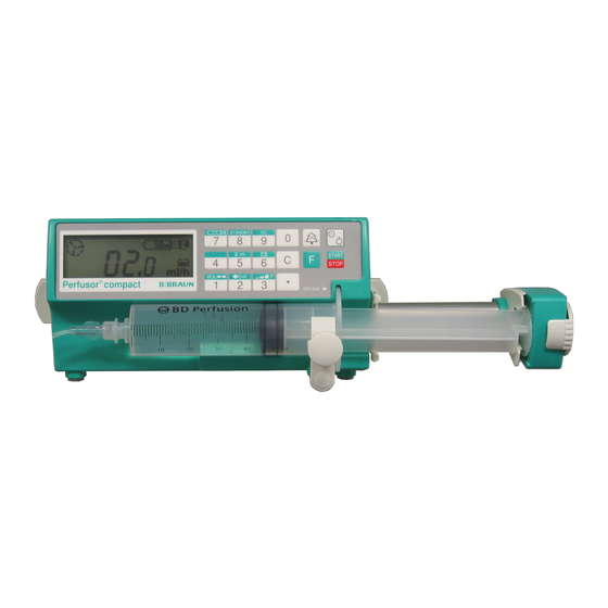
Дозатор шприцевой Perfusor Compact S ф.B Braun, Германия |
||||||
|
||||||
|
||||||
|
||||||
|
||||||
|
||||||
|
||||||
|
||||||
|
||||||
|
||||||
|
||||||
|
||||||
|
||||||
|
||||||
|
||||||
|
||||||
|
||||||
|
||||||
|
||||||
|
||||||
|
||||||
|
||||||
|
||||||
|
||||||
|
||||||
|
||||||
|
||||||
|
||||||
|
||||||
|
||||||
|
||||||
|
||||||
|
||||||
|
||||||
|
||||||
|
||||||
|
||||||
|
||||||
|
||||||
|
||||||
|
||||||
|


 В общем ошибка 046 и 138 возникает в результате нарушения связи между головой с тензодатчиком и платой управления, а именно в моем случае оказался неисправен операционный усилитель в голове где платка маленькая с тензодатчиком стоит, опрашивая голову плата не получала внятного ответа и падала в ошибку. Маркировка на операционнике не внятная идентифицировать не получается. Пришлось рисовать схему с платы вследствии долгих раздумий и шараханий по инету всплыла микра AD623, которая является инструментальным усилителем с автоматической коррекцией нуля (вот как сам в первый раз услышал это длиное понятие) стоит у нас в магазе 350 руб правда в смдшном корпусе не было взял в диповском так для проверки, подпаялся к плате и о чудо аппарат ожил и пашет как не в чем не бывало. Схему маленькой платы которая стоит в голове могу скинуть единственное там нет номиналов кондеров да и фиг с ними. Таким образом оживилосб 2 прибора проблема оказалась именно в операционнике, еще в одном проблема с тензодатчиком так как при подключении исправного ошибка пропадает. Никто не подскажет маркировку тензодатчика случаем, и можно ли в теории заменить его просто мостом из резисторов???, единственная функция которая перестанет быть это индикация оклюзии, да и фиг с ним для нас это не критично
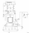


- Page 1
Infusomat® Space P and Accessories Instructions for Use It is recommended that all pumps at your care unit are equipped with the same software version or in parallel Valid for software 687N use with Software M. -
Page 2: Table Of Contents
CONTENTS Infusomat® Space P Overview ………………..3 Symbols on Product ……………………5 Patient Safety ……………………6 Menu Structure / Navigation………………..10 Chapter 1 Operation ………………….13 1.1 Start of Infusion…………………….13 1.2 Entry With Different Combinations of Rate, VTBI (= Volume To Be Infused) and Time……………………….16 1.3 Bolus Application……………………17 1.4 Infusion Line Change and New Therapy Start …………..18 1.5 End of Infusion ………………………19…
-
Page 3: Infusomat® Space P Overview
INFUSOMAT® SPACE P OVERVIEW I N F U S O M AT ® S PA C E P O V E R V I E W Arrow up and -down Press to reset single values Scroll through menus, change setting of numbers from to zero and switch back to Press to 0-9, answer Yes/No questions.
- Page 4
For vertical position push lever down and rotate either way until lever clicks into notch. Push lever for rotation. Caution: A maximum of three B. Braun Space pumps can be stacked together only in horizontal pump position when used with the PoleClamp SP. -
Page 5: Symbols On Product
SYMBOLS ON PRODUCT S Y M B O L S O N P R O D U C T…
-
Page 6: Patient Safety
Use. Operation • The initial training of the Infusomat® Space P is to be performed by B. Braun sales personnel or other authorized persons. After each software update, the user is required to inform himself about the changes to the device and accessories in the instructions for use.
- Page 7
PATIENT SAFETY • Installation in medically used rooms must comply with the appropriate regulations (e.g. VDE 0100, VDE 0107 or IEC-publications). Observe national specifications and deviations. Caution: Operate the pump at least 25 cm from flammable anaesthetics to prevent explosion. •… - Page 8
PATIENT SAFETY Other components • Use only pressure-proof and compatible disposable items (min. 2 bar/ 1500 mm Hg) to avoid influencing performance data — which would result in impairing patient safety. • Where several infusion lines are connected on one single vascular access, the possibility of the lines exerting a mutual influence over each other cannot be excluded. - Page 9
PATIENT SAFETY • When ending PCA and starting it again the therapy data are set to default values. • Using the demand button also the patient is a permitted user. With the demand button only a PCA-bolus can be requested. This is limited to pre- defined doses by drug list and pump settings. -
Page 10: Menu Structure / Navigation
MENU STRUCTURE / NAVIGATION MENU STRUCTURE / NAVIGATION Cutline On/Off button Clear button Door open button OK button Start/Stop button Keypad with arrow up, -down, -left, -right button Bolus button Connection button All display screen shots are examples and may be different when related to an individual patient and individualized therapy.
- Page 11
MENU STRUCTURE / NAVIGATION Display Meaning All status information is available in the bottom line of the display. The desired information can be selected by using and will be displayed permanently thereafter (e. g. drug long name, current system pressure etc.). has been pressed while the pump is infusing. - Page 12
MENU STRUCTURE / NAVIGATION Start Up Main Special Options Status Menu Menu Functions Menu Menu Line Dose Rate Occlusion Intermediate Dose selection Calculation Pressure volume Intermediate Prime ? Concentration Drug Library Data Lock amount Use last Change-over Bolus Intermediate Weight therapy ? from Rate… -
Page 13: Chapter 1 Operation
OPERATION Chapter 1 OPERATION 1.1 Start of Infusion • Ensure that the pump is properly installed. Check the equipment for completeness and damages. Do not attach the infusion bottle below the pump level. • Put the spike vertically into the infusion bottle. Fill the bottom part of the drop chamber by max.
- Page 14
OPERATION Chapter 1 Press down the opening lever. 1. Mind flow direction while inserting the infusion line (s. pictogramm) to prevent the danger of backflow. 2. Completely insert and then gently press the infusion line into the guidance and the sensors. 3. - Page 15
OPERATION Chapter 1 is properly occluding the IV set and the door extension hook is not broken. If the door hook is found damaged or broken remove the pump from service. Caution: If a wrong line is selected the time until the pump goes into a pressure alarm may be prolonged. -
Page 16: Entry With Different Combinations Of Rate, Vtbi (= Volume To Be Infused) And Time
OPERATION Chapter 1 upstream sensor calibrates on the current existing underpressure in the line and air might pass the AirStop membrane. In this case please ensure that the the drip chamber is refilled and then open the door for recalibration of the upstream sensor.
-
Page 17: Bolus Application
OPERATION Chapter 1 a) Target symbol is placed in front of VTBI: • Change of VTBI => Adjustment of time. Old and new target: VTBI • Change of time => Adjustment of rate. Old and new target: VTBI b) Target symbol is placed in front of time: •…
-
Page 18: Infusion Line Change And New Therapy Start
OPERATION Chapter 1 1.4 Infusion Line Change and New Therapy Start Note: Always interrupt the patient connection before changing a line to avoid dosing errors. Never let the pump run unattended when changing the line. Check and clean the safety clamp regularly. •…
-
Page 19: End Of Infusion
OPERATION Chapter 1 Remove emergency aperture cover. Turn crank inside aperture to open the door. • Close the pump door, confirm the inserted line with and open the roller clamp. • If required, prime the pump with u. Then press to proceed.
-
Page 20: Standby Mode
SPECIAL FUNCTIONS Chapter 1 1.6 Standby Mode In the case of extended interruption, the user has the option to maintain the set values. • Press to stop the infusion. Then press for less than 3 sec. • Confirm that the pump is supposed to switch to standby by pressing u. •…
-
Page 21: Chapter 2 Advanced Operations
SPECIAL FUNCTIONS Chapter 2 ADVANCED OPERATIONS 2.1 Status Request of Pump when Infusion is Running Press to switch between run display and Main Menu while the device is infusing. Navigate through the menu using to check parameters. In order to check the menu parameters in the Status-/Options Menu, select «Status»…
-
Page 22: Chapter 3 Special Functions
SPECIAL FUNCTIONS Chapter 3 SPECIAL FUNCTIONS 3.1 Dosing Units and Dose Rate Calculation (Overview) The following list shows the units used in the pump: Gram family: ng, mcg, mg, g Unit family: mIU, IU, kIU, MIU Equivalents family: mEq Mole family: mmol Kilocalorie family: kcal Millitliter family:…
-
Page 23: Drug Library
SPECIAL FUNCTIONS Chapter 3 a Enter the concentration by entering the amount of the active ingredient and the volume. In order to do so set the values with and confirm with k. a If the patient’s weight does not need to be entered press l. to choose “weight”…
- Page 24
SPECIAL FUNCTIONS Chapter 3 Loading a drug (including the according parameters) from the Main Menu: • Go to Special Functions Menu and press l. • Open the drug library by pressing l. • Navigate through the list with and select the care unit with l. If you have already set the care unit once on your pump this step will be skipped for the next time. - Page 25
SPECIAL FUNCTIONS Chapter 3 Hard Limits: If the set rate/dose/bolus volume and bolus rate exceed the values stored in the drug library (hard limits), the drug will be rejected, a hint will be displayed and the pump will fall back into the drug selection. If this occurs while the pump is infusing the pump will continue to administrate. -
Page 26: Patient Controlled Analgesia (Pca)
SPECIAL FUNCTIONS Chapter 3 3.4 Patient Controlled Analgesia (PCA) For PCA a drug list with at least one drug activating the profile PCA is necessary. By this the conditions for an effective and safe therapy are defined. Switch on pump with and wait until self-check is finished.
-
Page 27: Barcoding
SPECIAL FUNCTIONS Chapter 3 The A/D-ratio indicates the percentage of administered and demanded boli thus giving an idea about the effectivity of the therapy. An acoustic confirmation of demanded boli can be activated and modulated by in Data Lock 3. Is a demand button connected, the therapy symbol looks like this: In case there is no demand button connected the therapy symbol looks like this:…
-
Page 28: Piggyback Function
SPECIAL FUNCTIONS Chapter 3 Piggyback Function The piggyback-mode offers the possibility to interrupt the current (primary) infusion temporarily in order to administer a piggyback (secondary) infusion. Above the pump the piggyback-infusion line is connected with a Y-connector to the administration set. The secondary infusion is supposed to be located approx. 20 cm higher than the primary infusion.
- Page 29
SPECIAL FUNCTIONS Chapter 3 The piggyback therapy can be repeated many times by changing the piggyback medicament or by reset of the piggyback medicament. • Go to „Set new Piggyback” in the Special Functions Menu and confirm with l. Note: The Piggyback infusion can be deleted by starting a new Piggyback and by pressing cancel and answering the question „Use last therapy“… -
Page 30: Ramp And Taper Mode
SPECIAL FUNCTIONS Chapter 3 3.7 Ramp and Taper Mode The Ramp and Taper Mode is designed to deliver infusions with gradual ramp up and taper down rates. The pump automatically calculates the rate increase and decrease required to match the total volume, time and ramp up/ramp down time parameters. It consists of 3 phases.
- Page 31
SPECIAL FUNCTIONS Starting Ramp and Taper via Drug Library: Note: Ramp and Taper settings have been configured in the Drug List Manager before and have been uploaded into the pump. • Switch on pump with and wait until self-check is finished. •… - Page 32
SPECIAL FUNCTIONS Chapter 3 Taper phase The pump linearly decreases the rate in the predefined time until it reaches the KVO rate Note: After starting infusion it is only possible to change rates, time and VTBI in the continuous phase. By editing (increasing/decreasing) the plateau rate, the therapy is recalculated. -
Page 33: Programm Mode
SPECIAL FUNCTIONS Chapter 3 3.8 Program Mode Program Mode is for infusion requiring a non-standard delivery pattern. The user de- fines a series of intervals (max. 12 intervals) by certain parameters (rate, time, volume) for each cycle. The pump automatically gives each programmed period, one after the other Example: Program Mode should only be performed by an experienced user being familiar with the principles of the Program Mode function and properly trained in using the present…
- Page 34
SPECIAL FUNCTIONS Chapter 3 The settings for the steps of the infusion are shown on the display. These settings, configured in the Drug List Editor, need to be confirmed with r. • To change the values, press to change and to confirm. -
Page 35: Intermittent Mode
SPECIAL FUNCTIONS Chapter 3 The Main menu informs about the current interval. The configured parameters can be checked by Program Parameter Menu in Main. Intermittent Mode The Intermittent Mode consists of 2 phases. This phases will be repeated. • Bolus phase: the configured bolus is active •…
- Page 36
SPECIAL FUNCTIONS Chapter 3 • Select the desired drug with and press l. The pump now offers the possible therapy profiles. • Select “Intermittent Mode” with and press l. The therapy settings for “Intermittent Mode” are shown on the display. •… -
Page 37: Dose Over Time
SPECIAL FUNCTIONS Chapter 3 • Enter the new value and press k. The pump continues infusion. Changing the bolus after start: If the user edits the bolus the therapy progression changes. • Press • Use to select Bolus and press l. •…
- Page 38
Note: The feature Dose Over Time always requires the usage of dosing units (i.e., mg or mg/kg patient weight). Before using Dose Over Time contact your local B. Braun representative! Starting Dose Over Time via Drug Library: Note: Dose Over Time settings have been configured in the Drug List Manager before and have been uploaded into the pump. -
Page 39: Chapter 4 Autoprogramming
AUTOPROGRAMMING Chapter 4 A U TO P R O G R A M M I N G Note: All normal pump functions remain in place when orders are received via autoprogramming. The pump can accept drug orders wirelessly from the EHR system or from SpaceStation with SpaceCom.
- Page 40
AUTOPROGRAMMING Chapter 4 Note: Order may be cancelled prior to confirming order. • Once all values are confirmed, the Main Menu is displayed. Note: Soft Limit alert will be issued if value exceeds any soft limits set in drug library, soft limit may be overridden or value re-programmed per institutional policy. - Page 41
AUTOPROGRAMMING Chapter 4 While in PIGGYback: • Message will appear on top of display indicating update is available for PRIMary. • Press key to view order. • Follow prompt, pressing to accept order or key to cancel and hold order for later. - Page 42
AUTOPROGRAMMING Chapter 4 Note: Changing values on any incoming order may only be done after confir- ming all values. Once all values are confirmed you may scroll to any value and open editor with to change value. Alternately, order may be cancelled and request made for revised order to be sent. -
Page 43: Chapter 5 Options
OPTIONS Chapter 5 O P T I O N S The options functions may be selected and changed while the pump is infusing or stopped. To edit a menu item, select “Options” in the Main Menu and press l. Then select desired function with and follow the Instructions for Use as described.
-
Page 44: Upstream Occlusion Pressure
OPTIONS Chapter 5 The editor is extended by maximal 3 dashes. Confirm new pressure level with and go back to Options Menu. In the Run Menu the top line shows the current infusion pressure. The bottom line and the 3 dashes before the symbol shows the pressure alarm settings.
- Page 45
OPTIONS Chapter 5 Level 1: A modification of values as well as a bolus application are not possible but a change of the disposable can be conducted. It is possible to navigate through all menus and status data can be checked. Starting, interrupting and switching the pump off is possible. -
Page 46: Bolus Rate
OPTIONS Chapter 5 In order to deactivate the function, select “Off” in the data lock, press k, enter the code and press again. 5.4 Bolus Rate • Open bolus rate in Options Menu with l. • Change bolus rate with and confirm setting with k.
-
Page 47: Macro Mode
OPTIONS Chapter 5 5.9 Macro Mode The infusion rate appears larger on the display when the macro mode is activated and the pump is infusing. • Open macro mode in Options Menu with l. • Answer Yes/No question by pressing to activate the macro mode.
-
Page 48: Chapter 6 Alarms
ALARMS Chapter 6 ALARMS The Infusomat® Space P is equipped with an audible and optical alarm signal. Alarm- Audible Optical signal Staff call User confirmation type signal Red LED Yellow LED Text Device flashes device alarm Press and follow Alarm and alarm the instruction on the code…
- Page 49
ALARMS Chapter 6 Display message Pre-alarm reason “VTBI near end“ The preselected volume is nearly infused. “Time near end“ The preselected time is almost over. “Battery nearly empty“ The battery is almost discharged. “KVO mode“ VTBI/time are reached and the pump continues the infusion at the KVO-rate. - Page 50
ALARMS Chapter 6 When pushing on the battery cover listen for “click”. “Standby time expired“ The set standby time has ended. Set new time or continue with previously set therapy. “No battery inserted“ It is not possible to use the pump without a battery pack. -
Page 51: Reminder Alarms
ALARMS Chapter 6 «Flow» Drop chamber is completely filled or leak in the system. Examine the line for damage and check the drop chamber. “Data were reset” Therapy and pump settings could not be restored. Enter therapy again. «Therapy data were reset» Therapy data could not be restored.
-
Page 52: Alarm Hints
ALARMS Chapter 6 6.4 Alarm Hints If inproper entries are made the display states corresponding hints (e.g. “Bol.rate out of range”; “Download failed”; “The parameter can not be modified”). These hints disappear after a few seconds and don’t need to be confirmed.
-
Page 53: Battery Operation And Maintenance
BATTERY OPERATION AND MAINTENANCE Chapter 7 BATTERY OPERATION AND MAINTENANCE The battery has an operating lifetime of 4 hours at 100 ml/h when new. For optimal treatment of the battery, the device is equipped with protection against overcharge and deep depletion. The battery pack is charged by the pump during connection to mains.
- Page 54
BATTERY OPERATION AND MAINTENANCE Chapter 7 • ambient temperature • varying load (e.g. frequent boluses). The optimal life time of a battery pack will only be reached if it’s completely dischar- ged from time to time. A maintenance mode which conducts this battery maintenance is built in. -
Page 55: Start Up Graphs And Trumpet Curves
START UP GRAPHS AND TRUMPET CURVES Chapter 8 START UP GRAPHS AND TRUMPET CURVES Start Up Graphs Trumpet Curves The graphs show the accuracy/uniformity of flow in relation to time. They allow for the following: The delivery behaviour or delivery precision is essentially influenced by the type of the disposable used.
-
Page 56: Technical Data
Moisture protection IP 22 (fluid protected for horizontal usage) External power supply: • Rated voltage Via B. Braun SpaceStation or optional mains adaptor (rated voltage 100 … 240 V AC~, 50/60 Hz) for stand alone operation • External low voltage 11 ……
- Page 57
Delivery rate < 10 ml/h: KVO-rate 1 ml/h Delivery rate < 1 ml/h: KVO-rate = set rate (default setting 0.1 ml/h) Computer connection USB connection in combination with B. Braun interface lead CAN SP (8713230) including electrical insulation. Please pay attention to safety notices. Air detector Technical sensitivity: Detection of air bubbles ≥… - Page 58
TECHNICAL DATA Chapter 9 Sensitivity upstream sensor 9 levels from -120 mbar to -200 mbar (pressure reduction) Occlusion alarm pressures 9 levels up to 1.2 bar Occlusion pressure Time to occlusion alarm [min] at rate Note: At a rate [bar] [1 ml/h] [25 ml/h] [100 ml/h]… - Page 59
TECHNICAL DATA Chapter 9 EMC (ELECTROMAGNETIC COMPATIBILITY) - Page 60
TECHNICAL DATA Chapter 9… - Page 61
TECHNICAL DATA Chapter 9… - Page 62
TECHNICAL DATA Chapter 9… -
Page 63: Chapter 10 Warranty / Training / Tsc** / Service / Disinfecting / Disposal
• the Technical Safety Checks are carried out regularly. Warranty B. Braun provides 24 months warranty, as from the date of delivery, for every Infusomat® Space P (12 months for every Battery-Pack SP). This covers repair or replacement of parts damaged as a result of design/manufacturing errors or material defects.
- Page 64
WARRANTY / TRAINING / TSC* / SERVICE / DISINFECTING / DISPOSAL Chapter 10 Technical Safety Check* / Service The Technical Safety Check is recommended to be carried out every 2 years and should be documented. Servicing work must be carried out exclusively by trained personnel. - Page 65
Glutaral Aldehydes Glyoxal Peroxides Hydrogen Peroxide Active chlorine Sodium Hypochlorite Acid Citric Acid Note: Do not use Hexaquart® or other alkylamine containing disinfectants. Recommended: disinfectant for wiping available from B. Braun: Meliseptol® Foam pure, Melsitt 10% and Melsept SF 10%. - Page 66
Disposal The pumps as well as battery packs can be returned to B. Braun for further dis- posal. When taking care of disposing of disposables as well as infusion solutions, please consider the applicable hygiene and disposal regulations. -
Page 67: Technical Safety Chapter 11 Instructions For Use Accessory
Comfort additionaly includes a central alarm management and alarm LEDs. PoleClamp SP (8713130) A maximum of three B. Braun Space pumps and one SpaceControl can be stacked together when used with the PoleClamp SP. For detailed instructions on secure fixation of the PoleClamp SP please refer to «Overview Infusomat®…
- Page 68
INSTRUCTIONS FOR USE ACCESSORY Chapter 11 Note: A maximum of three plugs can be stacked upon each other in socket P2. Drop Sensor SP (8713175) The drop sensor provides an additional safety function and is therefore particularly recommended in connection with low delivery rates (10 ml/h). The connection of the Drop Sensor SP on the pump is located at the rear of the device, in the lower left corner. - Page 69
INSTRUCTIONS FOR USE ACCESSORY Chapter 11 2.) Connect CAN/USB converter to computer outlet as described in the Instructions for Use manual. Caution: The Interface Lead CAN SP is only to be used by the service department; never use while patient is connected. Note: A maximum of three plugs can be stacked upon each other in socket P2. - Page 70
INSTRUCTIONS FOR USE ACCESSORY Chapter 11 Note: Test staff call signalling before every use. The Infusomat® Space P offers three different staff call operating modes. They are displayed in the signalling scheme. Consider the staff call of the hospital when choosing an operating mode. Choose the operating mode via the service program. - Page 71
INSTRUCTIONS FOR USE ACCESSORY Chapter 11 P C A — A C C E S S O R I E S • Space PCA-Kit (REF 8713554) consisting of: : — Demand button — Hook and loop tape for fixation of the demand button at the patient s arm — Line fixation connection between hook and loop tape… -
Page 72: Ordering
ORDERING Art. No. B. Braun Infusomat® Space P (100 — 240 V) ……..8713070 Recommended accessories for the B. Braun Infusomat® Space P: SpaceStation…………………..8713140 SpaceCover Standard………………8713147 SpaceCover Comfort………………8713145 PoleClamp SP ………………….8713130 Power Supply SP EU III ………………8713110D Power Supply SP EU III 3.0m …………….8713123D Power Supply SP GB III………………8713111D…
- Page 73
Codan V86 P………………….43.4291 Hint: B. Braun does not have any influence on the quality of other lines. Changes in quality of those lines may have an influence on the technical characteristics of the pump. B. Braun therefore is not liable for deviations caused by disposables from other vendors than B. - Page 76
Manufactured by B. Braun Melsungen AG B. Braun Melsungen AG Sparte Hospital Care 34209 Melsungen 34209 Melsungen Germany Germany Tel +49 (0) 56 61 71-0 Tel.: +49 (0) 56 61 71-0 38911866 • Drawing No. I0687700201 Fax: +49 (0) 56 61 71-20 44 Printed on pulp bleached 100 % chlorine-free www.bbraun.com…
OP Expert
Joined: May 2009 Posts: 127 |
Hi all, I have a problem with bbraun perfusor compact s!On a display appears symbol «key« and on other pump appears an error code 046! How can I reset them ?Does anyone have service manual for them ? Regards! |

| Recruitment / Jobs |
|
|

|
|
|
|
Joined: May 2009 Posts: 72
Scholar |
|
|
Scholar
Joined: May 2009 Posts: 72 |
Jevremco on the E046, the last pump I had was merely a case of fastening the syringe size potentiometer clip (Not at all in line with the error code index of the OEM)and re-calibrating the occlusion limit. If you don’t have the correct guages I would suggest you get in touch with Braun for a set. (I found using a generic set just didn’t cut the cake «so to speak» during a previous battle with a compact s)
keeping faith is old school….. |

|
|
|
|
Joined: Apr 2005 Posts: 371 Sage |
|
|
Sage Joined: Apr 2005 Posts: 371 |
Checking for DAC error as indicated in the manual. |
2.1
2
Software
LC display
Description
1
Different syringe recognition
2
Different FP- and CMP condition
3
Rate of FP- and CMP different
4
Different function mode
5
Different rate of delivery
6
Different target volume
7
Different step volume (low)
8
Different motor steps
19
State/motor state
20
Invalid normal state
21
return from PlcMain
22
Unexpected reset
28
No sync at Plc_Down
29
No sync at Plc_On
30
Different CMP/FP mode ports
31
Invalid mode ports
32
Invalid variable values
33
Error in ROM test
34
Different software version
40
Unexpected interrupt
49
Faulty sensor sync
51
Motor on during reverse run
52
Step cumulation > 10 steps
53
Illegal setting of Mot_Ok
54
Different recognition of direction of rotation
55
Reverse polarity of motor
Table 2 — 1 (Part 1 of 2)
2 — 2
In case of a unit malfunction a continuous signal is activated, and
the function processor displays an alarm and an error code. The
error code of the control microprocessor can be queried with the
F button. Please state both error codes if you have any questions.
Acknowledge alarm and switch device off.
Device Alarms of the Function Processor
Perfusor® compact, 2.1 gb
- Manuals
- Brands
- B. Braun Manuals
- Medical Equipment
- Perfusor compact
- Service manual
-
Contents
-
Table of Contents
-
Troubleshooting
-
Bookmarks
Quick Links
0 — 10
Perfusor® compact
Service Manual
Version 2.1 english
0 —
Related Manuals for B. Braun Perfusor compact
Summary of Contents for B. Braun Perfusor compact
-
Page 1
0 — 10 Perfusor® compact Service Manual Version 2.1 english… -
Page 2
This Service Manual is valid for Designation Part No.: Perfusor® compact (230 …240 V, Euro cable) ..0871 4827 Perfusor® compact (230 …240 V, BSI cable) ..0871 4828 Perfusor®… -
Page 3: Table Of Contents
Table of Contents Important Preliminary Remarks Service Work Page 0 — 5 Technical Safety Checks Page 0 — 5 Current Versions Page 0 — 5 Revision Service Page 0 — 5 Responsibility of the Manufacturer Page 0 — 6 Quality Management Page 0 — 6 Checks and Repair…
-
Page 4
Table of Contents Carrying Handle Page 4 — 12 Drive Page 4 — 12 Axial Positioner Page 4 — 13 Drive Board Page 4 — 14 Drive Head Page 4 — 15 Housing Bottom Part, Complete Page 4 — 17 Checks after Repair General Page… -
Page 5: Service Work
You will be included in the revision service after: technical training by B. Braun Melsungen or a written order placed with the sales department of B. Braun (fee required). Perfusor® compact, 2.1 gb 0 — 5…
-
Page 6: Responsibility Of The Manufacturer
B. Braun unit. Quality Management B. Braun is certified in accordance with DIN EN ISO 9001 and ISO 13485. This certification also includes maintenance and serv- ice. The unit has the CE label. The CE label confirms that the device corresponds to the “Directive of the Council for Medical Products…
-
Page 7: Spare Parts And Test Equipment
Service personnel are responsible for the calibration of their test equipment. Original test equipment can be calibrated at the works of B. Braun. Further information is available upon request. Setting Off Additional notes and warnings are set off as follows:…
-
Page 8: List Of Abbreviations
Important Preliminary Remarks References to item numbers in figures are shown as follows (Fig.: 1 — 1 / Item In this case “Fig.: 1 – 1“ is the figure number and “Item 1“ the item number within the figure. When the Service Manual is stored as pdf-file, these references are displayed green.
-
Page 9: Technical Training
Entry for Technical Training Application for a technical training course must be made via the responsible representative. Ordering of Spare Parts and Test Equipment Please contact your local B. Braun subsidary. International Technicians (Intercompany) Nadja Machal Fax: +49 5661 / 75 -47 89 e-mail: nadja.machal@bbraun.com…
-
Page 10
Contact Persons For your notes: 0 — 10 Perfusor® compact, 2.1 gb… -
Page 11: Physical Construction
1 — 4 System Overview Physical Construction The Perfusor compact is a compact, stacking, portable and light- weight syringe pump which is used for precise dosing of small to high volumes of fluids in infusion and alimentary therapies. The standard delivery rate range is 0.1 to 99.9 ml/h (in increments of 0.1 ml/h).
-
Page 12: Function
System Overview Function The electronics of the Perfusor compact consists of the following components: 1. A-Module with MFC board as the central power supply and interface 2. E-Module as operating and control unit 3. Drive unit, consisting of drive board with the complete sensor technology, light…
-
Page 13: Accessories
System Overview Accessories Designation Ord. No. Unit connecting lead 200-240 V ….3450 2718 Unit connecting lead 100-120 V….3450 5423 Pole clamp (universal clamp, rotating) .
-
Page 14
System Overview For your notes: 1 — 4 Perfusor® compact, 2.1 gb… -
Page 15: Approved Software Versions
2 — 6 Software Approved Software Versions The software and hardware revision level is displayed on the LC- Position 1 2 3 4 5 6 7 8 9 display when the unit is switched on. The characters on the dis- play must correspond with the indication on the instructions for Digit P L A A 0 0 7 2 1…
-
Page 16: Error Messages And Alarms
Software Error Messages and Alarms In case of a unit malfunction a continuous signal is activated, and the function processor displays an alarm and an error code. The error code of the control microprocessor can be queried with the F button. Please state both error codes if you have any questions. Acknowledge alarm and switch device off.
-
Page 17
Software LC-Display Description Invalid syringe Overflow of motor step counter No sync at Mot_Test Different SW button NEC<>H8 Timeout KBD watchdog Error in switch-on test Control timer overflow (int) Control timer underflow Control timer overflow 100 ms cycle overflow Tim_WaitUntil overflow Error upon reading of EEPROM Error of EEP data consistency Ad difference between NEC/H8… -
Page 18
Software Device alarms of the control microprocessor LC-Display Description Unexpected reset Unexpected hardware interrupt Access of zero pointer Attempted division by zero Internal software error State/motor state Invalid variable values Invalid operating condition Illegal mode – port value H8 indicates GA F14_H8GA_K16 Different software versions Double CRC error Different states… -
Page 19
Software LC-Display Description Keyboard timeout error Cycle > 100 ms Time > Until Watchdog interrupt Error when waiting for H8 Time-out when switching H8 on Time-out when switching H8 off No sync at Plc_Down No sync at Plc_On CMP/FP timer – end sync error Different phases (busy) Different phases (idle) Motor on at reverse steps… -
Page 20
Software For your notes: 2 — 6 Perfusor® compact, 2.1 gb… -
Page 21: Software Compatibility
3 — 16 Service Program Software Compatibility Designation Ord. No. Interface cable ……. 0871 1661 Compatibility Unit Software Service Program…
-
Page 22
Program“ p. 3 — 11). When the Service Program is installed and the PC is connected to the Perfusor compact, the following functions can be executed: Drive calibration Reading / loading pump data Displaying operation values Displaying and changing parameters… -
Page 23: Working With The Service Program
Service Program Configuration 1. Select the language, interface and the screen display desired File Configuration in the menu. 2. Acknowledge with Working with the Service Program Preparation 1. Connect service cable (Fig.: 3 — 2 / Item 2) to MFC connector (Fig.: 3 — 2 / Item 1) and the PC serial port (COM 1 or COM 2).
-
Page 24
Service Program Unit Calibration The unit is to be calibrated (see „Unit Calibration“ p. 3 — 14) ter the E-Module or the drive was replaced or the bolus rate was changed. Defaut Data The Service Program contains the Default.dat file with the factory settings of the unit. -
Page 25: What To Do If (Trouble Shooting)
Is the service cable connection okay? Is the MFC correctly connected? … the communication starts and is then interrupted? Then: Press the ON-key on the Perfusor compact until the sym- bols disappear..the unit does not accept any syringe after a service was car- ried out? Is syringe selection set to „free type“, but „free type“…
-
Page 26: Menu Description
Service Program Menu Description Info Menu 1. Version number of the Service Program File Info Click on the line before , then click on Fig.: 3 — 3 File Menu Connect (F1) Starts communication with the Perfusor® compact. Save (F8) Saves the unit data, e.g.
-
Page 27
Service Program Write (F7) The modified values must be loaded in the Perfusor® compact after calibration, modification of data or the serial number was input. The status displays „SNr“, „DAbg“ and „LAbg“ must be ticked. Writing of data is acknowledged by „Writing com- pleted successfully“. -
Page 28
Fig.: 3 — 8 Table and free type Allows to select all syringe types which are saved and can be loaded in the Perfusor compact. Defines that only OPS 50 ml and OPS 20 ml syringes can be used. Fig.: 3 — 9 3 — 8 Perfusor®… -
Page 29
(see „Syringe Table and and Quick Reference Guide“ p. 4 — 5) Fig.: 3 — 11 3. ROM 20 ml/ ROM 50 ml table Display of the syringe types saved in the Perfusor compact ROM. Modes Menu 1. Modification data Display and setting of: max. -
Page 30
Service Program For units with unit software up to PLAA00071.1: (Service Program version 6.001) 0 = continuous tone with 3 Hz intermittent 1 = continuous tone Note Please pay attention to the notes given with the staff call cable. CAUTION The pressure stage which was set last and the syringe type that was selected last are overwritten with the pump settings when the unit is switched off. -
Page 31: Procedural Instructions For Inspection After Modifications Via The Service Program
Service Program Procedural Instructions for Inspection after Serial Number Modifications via the Service Program 1. Switch on unit. 2. Start the Service Program. 3. Read out EEPROM and compare the serial number in Calibra- tion / Serial number with the serial number indicated on the type plate.
-
Page 32
Service Program Alarm Tone 1. Switch on unit. 2. Insert syringe and confirm (or select), e.g. OPS 50 ml. 3. Enter rate and actuate the Start button to start delivery. 4. Open syringe holder, an alarm is triggered. 5. Compare the alarm tone with the settings: For units with unit software up to PLAA00063.3 (Service Program version 55004): 0 = continuous tone with 3 Hz intermittent… -
Page 33
Service Program C {number of the 50 ml free type} F – alarm (if the syringe is accepted, then the syringe selection setting is not correct!) Test for setting the free type or EEPROM: 3. Open holder, press keys 7 C {number of the 20 ml free type} F and keys 7 C {number of the 50 ml free type} F –… -
Page 34: Unit Calibration
Service Program Syringes 50 ml Free Type / Syringe Type Number 1. Press keys 7 C {number of the 50 ml free type} F – syringe is accepted (if an alarm is triggered, then the syringe selection setting is not correct!) Check whether the free type was marked on the unit (please see syringe table).
-
Page 35
Service Program Calibration point 2: Force 60 N, PWM max. 78% Replace drive when the PWM values are exceeded. EEPROM Write 7. Transfer data to device via menu (F7). File 8. Data can be saved on the hard disk of the PC via menu Save (F8) if necessary. -
Page 36: Checklist After Operation Of The Service Program Page
Service Program Checklist after Operation of the Service Program CAUTION Does not replace Check after Repair. Condition as delivered Condition as shipped Test ok Calibration Serial number Modes max. basal rate Modes Bolus rate Modes Staff call dynamic dynamic static static Off-alarm Off-alarm…
-
Page 37: Fundamental Repair Information
If the battery pack is used, then the device is to be switched on with mains connection. Note Defective batteries must be disposed of according to the regula- tions, e.g. return to B. Braun (see „Return of Spare Parts and Test Equipment“ p. 0 -…
-
Page 38
Unit Elements Designation Ord. No. Small parts kit for 5 units ….. . . 3450 7736 containing: 45 KB 30×16, 5 split rivet for quick reference guide, 5 screw split rivet for battery compartment cover, 5 blind plug for syringe holder,… -
Page 39
Unit Elements Open unit 1. Loosen 5 screws from the bottom. 2. Open housing carefully, then 3. Pull off the ribbon cable from the E-Module and the connec- tion cable from the motor. Hold the white board holder on the E-Module when disconnecting! 4. -
Page 40
Unit Elements Fig.: 4 — 3 A-Module board (from serial number 38101 on) Close Unit 1. Close unit in reverse order of opening. Note Do not squeeze motor cable. Checks after Repair Procedural instructions (see „Procedural Instructions for Inspec- tion after Modifications via the Service Program“ p. -
Page 41: Syringe Table And And Quick Reference Guide
Unit Elements 4.2 Syringe Table and and Quick Reference Guide Designation Ord. No. Instructions for use, complete Language: German ……..3891 1302 English .
-
Page 42: Syringe Holder
Unit Elements 4.3 Syringe Holder Designation Ord. No. Syringe holder, complete ….. . . 3450 6608 with screw and cap Exchange 1.
-
Page 43: Battery Compartment Cover
Unit Elements 4.5 Battery Compartment Cover Designation Ord. No. Battery compartment cover ….. 3450 6632 Screwed split rivet Exchange 1. Screw out screwed split rivet. 2.
-
Page 44: A-Module
Unit Elements 4.7 A-Module Designation Ord. No. A-Module, complete, with board, MFC and buzzer . . . 3450 5288 (replaces A-Module up to serial number 38100) Buzzer ……..3450 8643 Exchange 1.
-
Page 45: Ls-Clip
Unit Elements 4.8 LS-Clip Designation Ord. No. LS-clip ……..3450 7710 Exchange 1.
-
Page 46: E-Module
Unit Elements 4.9 E-Module Designation Ord. No. E-Module with DIANET ……3450 6675 Star E-Module with DIANET .
-
Page 47: N-Module
Unit Elements 4.10 N-Module Designation Ord. No. N-Module (220 -240 V) ……3450 6683 N-Module (100 -120 V) ……3450 6730 Exchange 1.
-
Page 48: Carrying Handle
Unit Elements 4.12 Carrying Handle Designation Ord. No. Carrying handle ……. 3450 6438 Exchange Carrying handle Note…
-
Page 49: Axial Positioner
Unit Elements 8. Pay attention to cable laying (please see Fig.: 4 — 14). 9. Close unit (see „Close Unit“ p. 4 — Note Do not squeeze cable. 10. Calibrate in Service Program (see „Calibration after Replace- ment of Drive“ p.
-
Page 50: Drive Board
Unit Elements 4.15 Drive Board Designation Ord. No. Drive board ……..3450 6691 with main PCB and satellite boards for syringe size recognition and recognition of direction of rotation…
-
Page 51: Drive Head
Unit Elements 11. Calibrate in Service Program (see „Calibration after Replace- ment of Drive“ p. 7 — Fig.: 4 — 18 4.16 Drive Head Designation Ord. No. Drive head, complete ……3450 1720 Toggle .
-
Page 52
Unit Elements 3. Unscrew four screws. Drive head housing Cap for drive head housing 4. Remove cover for drive head housing with toggle, lever and Release shaft release shaft (square). 5. Sketch the cable layout. Note Pay attention to spring when removing the housing cover. 6. -
Page 53: Housing Bottom Part, Complete
Unit Elements 4.17 Housing Bottom Part, Complete Designation Ord. No. Housing bottom part, complete ….3450 6594 Exchange 1. Open housing (see „Open unit“ p.
-
Page 54
Unit Elements For your notes: 4 — 18 Perfusor® compact, 2.1 gb… -
Page 55: General
5 — 6 Checks after Repair General Carry out the respective check blocks depending on the activity performed. The individual steps are described hereafter in more detail. Carry out an overload test if the unit has been dropped (see „Over- load Check“…
-
Page 56: Visual Inspection
Checks after Repair Visual Inspection 1. Check unit for cleanliness, completeness, damage and faults affecting safety. Pay special attention to the following parts: Syringe holder, axial positioner, drive head Syringe table and quick reference guide Membrane keyboard Battery compartment cover, battery compartment and — contacts Unit feet MFC connector…
-
Page 57
Checks after Repair Operation 1. Open lock (drive head). Check push-button sensor alarm. The piston rod symbol must flash on the LC-display if a syringe was not inserted. 2. Insert calibration gauge in the OPS 50 ml slot and close sy- ringe holder. -
Page 58
Checks after Repair Pressure Cut-Off CAUTION The limit values of the Checklist for Checks after Repair do not correspond to the TSC values. 1. Set pressure stage 1 (key sequence F 3 C 1 F START). 2. Pump continues to deliver at 96.0 ml/h and switches off when the specified pressure is reached. -
Page 59: Electrical Safety
Checks after Repair Pre- and End Alarm 1. Draw up a 50 ml OPS syringe to 6 ml and insert syringe. 2. Confirm OPS with F-button 3. Change delivery rate to 99 ml/h (key sequence C 9 9) and press START. Pump delivers and triggers pre-alarm at a volume of 5 ml.
-
Page 60
Checks after Repair For your notes: 5 — 6 Perfusor® compact, 2.1 gb… -
Page 61
6 — 2 Maintenance The unit is maintenance-free. A Technical Safety Check (TSC) (see „Technical Safety Check TSC“ p. 7 — 1) is to be carried out every 24 months to check the op- erational capability of the Perfusor® compact. Perfusor®… -
Page 62
Maintenance For your notes: 6 — 2 Perfusor® compact, 2.1 gb… -
Page 63
Index 01 (Master — to be added to the documentation) Checklist for Technical Safety Checks – Every 24 Months Unit: Perfusor compact infusion syringe pump User Manufacturer: B. Braun Melsungen AG Observe the service manual and the instructions for use. All measured values are to be documented. -
Page 64
Technical Safety Check TSC Index 01 (Master — to be added to the documentation) 5. Electrical Safety 6. Accessories 7. Optional Enter MFC, battery etc.: Rate limitation ml/h ..acc. to EN 60601 (VDE 0750/0751) ……….Bolus rate Protective conductor resist- limitation ml/h .. -
Page 65: Visual Inspection
8 — 6 Procedural Instructions on the TSC Visual Inspection Unit, in General Completeness, external damage, safe fit of the battery compart- ment cover and syringe table. Check cleanliness of device. Check labels and readability. Syringe Fastening Check function with OPS 50 ml syringe. (Syringe holder, axial positioner, drive head, clamp, and push-but- ton sensor) Membrane Keyboard…
-
Page 66: Functional Inspection
Procedural Instructions on the TSC Functional Inspection Switch on unit 1. Switch on Perfusor and keep ON-button pressed for max. 20 sec. Check the screen display during this time. A device alarm is triggered if the button is actuated for more than 20 sec. 2.
-
Page 67: Pressure Cut-Off
Procedural Instructions on the TSC 11. Pull syringe holder. Staff call: red LED in MFC service connector lights up. Drive stops. Note The following staff call modes can be selected in the Service Pro- gram if the unit is switched off: static, dynamic with and without alarm.
-
Page 68: Syringes
Procedural Instructions on the TSC 11. Wait until the current step gauge is completely released. Then remove current step gauge and close syringe holder slowly. Syringes 1. Check syringe selection (see „Syringe / Syringe Selection“ p. 3 — 12). Note internal = table in ROM EEPROM…
-
Page 69
Procedural Instructions on the TSC 8 — 5 Perfusor® compact, 2.1 gb… -
Page 70
Procedural Instructions on the TSC For your notes: 8 — 6 Perfusor® compact, 2.1 gb… -
Page 71
9 — 2 Test Equipment and Special Tools Designation Ord. No. Zero point gauge ……3450 1703 Calibration gauge (6.6 -80 N) . -
Page 72
Test Equipment and Special Tools For your notes: 9 — 2 Perfusor® compact, 2.1 gb… -
Page 73
10 — 4 Spare Parts List 10 — Designation Ord. No. Perfusor® compact Battery pack ……. . . 3450 1690 Small parts kit for 5 units . -
Page 74
Spare Parts List Drive, complete (with motor) ….3450 6624 Straight pin lock ……3450 9100 Axial positioner . -
Page 75
10 — 4 Designation Ord. No. Poleclamp Pole clamp (universal clamp, rotating) … . 3450 9054 Universal Clamp (Poleclamp) Universal clamp, complete ….. . 3450 5857 Universal clamp . -
Page 76
For your notes: Perfusor® compact, 2.1 gb… -
Page 77
11 — 2 Index 11 — Alarms ……… . . 2 — 2 List of abbreviations . -
Page 78
Index Test equipment ……..9 — 1 Trouble shooting . -
Page 79: Revision Service-Documentation
A — 2 Appendix Revision Service-Documentation Version 2.1 This Service Manual was approved by B. Braun on 16.03.2006. This manual has been completely revised. The most important changes are listed below: Changed manual structure New software New spare parts Total list of spare parts…
-
Page 80
Appendix A For your notes: A — 2 Perfusor® compact, 2.1 gb… -
Page 81: Description
B — 2 Modification Instructions for Syringe Holder Description The syringe holder must be modified as recognition of syringes with a large outer diameter by the light barrier system was diffi- cult. This modification is limited to installation of a washer. Modification 1.
-
Page 82
Modification Instructions for Syringe Holder For your notes: B — 2 Perfusor® compact, 2.1 gb…
|
Дозатор шприцевой Perfusor Compact S ф.B Braun, Германия |
||||||
|
||||||
|
||||||
|
||||||
|
||||||
|
||||||
|
||||||
|
||||||
|
||||||
|
||||||
|
||||||
|
||||||
|
||||||
|
||||||
|
||||||
|
||||||
|
||||||
|
||||||
|
||||||
|
||||||
|
||||||
|
||||||
|
||||||
|
||||||
|
||||||
|
||||||
|
||||||
|
||||||
|
||||||
|
||||||
|
||||||
|
||||||
|
||||||
|
||||||
|
||||||
|
||||||
|
||||||
|
||||||
|
||||||
|
||||||
|
||||||
|
- Page 1
Infusomat® Space P and Accessories Instructions for Use It is recommended that all pumps at your care unit are equipped with the same software version or in parallel Valid for software 687N use with Software M. -
Page 2: Table Of Contents
CONTENTS Infusomat® Space P Overview ………………..3 Symbols on Product ……………………5 Patient Safety ……………………6 Menu Structure / Navigation………………..10 Chapter 1 Operation ………………….13 1.1 Start of Infusion…………………….13 1.2 Entry With Different Combinations of Rate, VTBI (= Volume To Be Infused) and Time……………………….16 1.3 Bolus Application……………………17 1.4 Infusion Line Change and New Therapy Start …………..18 1.5 End of Infusion ………………………19…
-
Page 3: Infusomat® Space P Overview
INFUSOMAT® SPACE P OVERVIEW I N F U S O M AT ® S PA C E P O V E R V I E W Arrow up and -down Press to reset single values Scroll through menus, change setting of numbers from to zero and switch back to Press to 0-9, answer Yes/No questions.
- Page 4
For vertical position push lever down and rotate either way until lever clicks into notch. Push lever for rotation. Caution: A maximum of three B. Braun Space pumps can be stacked together only in horizontal pump position when used with the PoleClamp SP. -
Page 5: Symbols On Product
SYMBOLS ON PRODUCT S Y M B O L S O N P R O D U C T…
-
Page 6: Patient Safety
Use. Operation • The initial training of the Infusomat® Space P is to be performed by B. Braun sales personnel or other authorized persons. After each software update, the user is required to inform himself about the changes to the device and accessories in the instructions for use.
- Page 7
PATIENT SAFETY • Installation in medically used rooms must comply with the appropriate regulations (e.g. VDE 0100, VDE 0107 or IEC-publications). Observe national specifications and deviations. Caution: Operate the pump at least 25 cm from flammable anaesthetics to prevent explosion. •… - Page 8
PATIENT SAFETY Other components • Use only pressure-proof and compatible disposable items (min. 2 bar/ 1500 mm Hg) to avoid influencing performance data — which would result in impairing patient safety. • Where several infusion lines are connected on one single vascular access, the possibility of the lines exerting a mutual influence over each other cannot be excluded. - Page 9
PATIENT SAFETY • When ending PCA and starting it again the therapy data are set to default values. • Using the demand button also the patient is a permitted user. With the demand button only a PCA-bolus can be requested. This is limited to pre- defined doses by drug list and pump settings. -
Page 10: Menu Structure / Navigation
MENU STRUCTURE / NAVIGATION MENU STRUCTURE / NAVIGATION Cutline On/Off button Clear button Door open button OK button Start/Stop button Keypad with arrow up, -down, -left, -right button Bolus button Connection button All display screen shots are examples and may be different when related to an individual patient and individualized therapy.
- Page 11
MENU STRUCTURE / NAVIGATION Display Meaning All status information is available in the bottom line of the display. The desired information can be selected by using and will be displayed permanently thereafter (e. g. drug long name, current system pressure etc.). has been pressed while the pump is infusing. - Page 12
MENU STRUCTURE / NAVIGATION Start Up Main Special Options Status Menu Menu Functions Menu Menu Line Dose Rate Occlusion Intermediate Dose selection Calculation Pressure volume Intermediate Prime ? Concentration Drug Library Data Lock amount Use last Change-over Bolus Intermediate Weight therapy ? from Rate… -
Page 13: Chapter 1 Operation
OPERATION Chapter 1 OPERATION 1.1 Start of Infusion • Ensure that the pump is properly installed. Check the equipment for completeness and damages. Do not attach the infusion bottle below the pump level. • Put the spike vertically into the infusion bottle. Fill the bottom part of the drop chamber by max.
- Page 14
OPERATION Chapter 1 Press down the opening lever. 1. Mind flow direction while inserting the infusion line (s. pictogramm) to prevent the danger of backflow. 2. Completely insert and then gently press the infusion line into the guidance and the sensors. 3. - Page 15
OPERATION Chapter 1 is properly occluding the IV set and the door extension hook is not broken. If the door hook is found damaged or broken remove the pump from service. Caution: If a wrong line is selected the time until the pump goes into a pressure alarm may be prolonged. -
Page 16: Entry With Different Combinations Of Rate, Vtbi (= Volume To Be Infused) And Time
OPERATION Chapter 1 upstream sensor calibrates on the current existing underpressure in the line and air might pass the AirStop membrane. In this case please ensure that the the drip chamber is refilled and then open the door for recalibration of the upstream sensor.
-
Page 17: Bolus Application
OPERATION Chapter 1 a) Target symbol is placed in front of VTBI: • Change of VTBI => Adjustment of time. Old and new target: VTBI • Change of time => Adjustment of rate. Old and new target: VTBI b) Target symbol is placed in front of time: •…
-
Page 18: Infusion Line Change And New Therapy Start
OPERATION Chapter 1 1.4 Infusion Line Change and New Therapy Start Note: Always interrupt the patient connection before changing a line to avoid dosing errors. Never let the pump run unattended when changing the line. Check and clean the safety clamp regularly. •…
-
Page 19: End Of Infusion
OPERATION Chapter 1 Remove emergency aperture cover. Turn crank inside aperture to open the door. • Close the pump door, confirm the inserted line with and open the roller clamp. • If required, prime the pump with u. Then press to proceed.
-
Page 20: Standby Mode
SPECIAL FUNCTIONS Chapter 1 1.6 Standby Mode In the case of extended interruption, the user has the option to maintain the set values. • Press to stop the infusion. Then press for less than 3 sec. • Confirm that the pump is supposed to switch to standby by pressing u. •…
-
Page 21: Chapter 2 Advanced Operations
SPECIAL FUNCTIONS Chapter 2 ADVANCED OPERATIONS 2.1 Status Request of Pump when Infusion is Running Press to switch between run display and Main Menu while the device is infusing. Navigate through the menu using to check parameters. In order to check the menu parameters in the Status-/Options Menu, select «Status»…
-
Page 22: Chapter 3 Special Functions
SPECIAL FUNCTIONS Chapter 3 SPECIAL FUNCTIONS 3.1 Dosing Units and Dose Rate Calculation (Overview) The following list shows the units used in the pump: Gram family: ng, mcg, mg, g Unit family: mIU, IU, kIU, MIU Equivalents family: mEq Mole family: mmol Kilocalorie family: kcal Millitliter family:…
-
Page 23: Drug Library
SPECIAL FUNCTIONS Chapter 3 a Enter the concentration by entering the amount of the active ingredient and the volume. In order to do so set the values with and confirm with k. a If the patient’s weight does not need to be entered press l. to choose “weight”…
- Page 24
SPECIAL FUNCTIONS Chapter 3 Loading a drug (including the according parameters) from the Main Menu: • Go to Special Functions Menu and press l. • Open the drug library by pressing l. • Navigate through the list with and select the care unit with l. If you have already set the care unit once on your pump this step will be skipped for the next time. - Page 25
SPECIAL FUNCTIONS Chapter 3 Hard Limits: If the set rate/dose/bolus volume and bolus rate exceed the values stored in the drug library (hard limits), the drug will be rejected, a hint will be displayed and the pump will fall back into the drug selection. If this occurs while the pump is infusing the pump will continue to administrate. -
Page 26: Patient Controlled Analgesia (Pca)
SPECIAL FUNCTIONS Chapter 3 3.4 Patient Controlled Analgesia (PCA) For PCA a drug list with at least one drug activating the profile PCA is necessary. By this the conditions for an effective and safe therapy are defined. Switch on pump with and wait until self-check is finished.
-
Page 27: Barcoding
SPECIAL FUNCTIONS Chapter 3 The A/D-ratio indicates the percentage of administered and demanded boli thus giving an idea about the effectivity of the therapy. An acoustic confirmation of demanded boli can be activated and modulated by in Data Lock 3. Is a demand button connected, the therapy symbol looks like this: In case there is no demand button connected the therapy symbol looks like this:…
-
Page 28: Piggyback Function
SPECIAL FUNCTIONS Chapter 3 Piggyback Function The piggyback-mode offers the possibility to interrupt the current (primary) infusion temporarily in order to administer a piggyback (secondary) infusion. Above the pump the piggyback-infusion line is connected with a Y-connector to the administration set. The secondary infusion is supposed to be located approx. 20 cm higher than the primary infusion.
- Page 29
SPECIAL FUNCTIONS Chapter 3 The piggyback therapy can be repeated many times by changing the piggyback medicament or by reset of the piggyback medicament. • Go to „Set new Piggyback” in the Special Functions Menu and confirm with l. Note: The Piggyback infusion can be deleted by starting a new Piggyback and by pressing cancel and answering the question „Use last therapy“… -
Page 30: Ramp And Taper Mode
SPECIAL FUNCTIONS Chapter 3 3.7 Ramp and Taper Mode The Ramp and Taper Mode is designed to deliver infusions with gradual ramp up and taper down rates. The pump automatically calculates the rate increase and decrease required to match the total volume, time and ramp up/ramp down time parameters. It consists of 3 phases.
- Page 31
SPECIAL FUNCTIONS Starting Ramp and Taper via Drug Library: Note: Ramp and Taper settings have been configured in the Drug List Manager before and have been uploaded into the pump. • Switch on pump with and wait until self-check is finished. •… - Page 32
SPECIAL FUNCTIONS Chapter 3 Taper phase The pump linearly decreases the rate in the predefined time until it reaches the KVO rate Note: After starting infusion it is only possible to change rates, time and VTBI in the continuous phase. By editing (increasing/decreasing) the plateau rate, the therapy is recalculated. -
Page 33: Programm Mode
SPECIAL FUNCTIONS Chapter 3 3.8 Program Mode Program Mode is for infusion requiring a non-standard delivery pattern. The user de- fines a series of intervals (max. 12 intervals) by certain parameters (rate, time, volume) for each cycle. The pump automatically gives each programmed period, one after the other Example: Program Mode should only be performed by an experienced user being familiar with the principles of the Program Mode function and properly trained in using the present…
- Page 34
SPECIAL FUNCTIONS Chapter 3 The settings for the steps of the infusion are shown on the display. These settings, configured in the Drug List Editor, need to be confirmed with r. • To change the values, press to change and to confirm. -
Page 35: Intermittent Mode
SPECIAL FUNCTIONS Chapter 3 The Main menu informs about the current interval. The configured parameters can be checked by Program Parameter Menu in Main. Intermittent Mode The Intermittent Mode consists of 2 phases. This phases will be repeated. • Bolus phase: the configured bolus is active •…
- Page 36
SPECIAL FUNCTIONS Chapter 3 • Select the desired drug with and press l. The pump now offers the possible therapy profiles. • Select “Intermittent Mode” with and press l. The therapy settings for “Intermittent Mode” are shown on the display. •… -
Page 37: Dose Over Time
SPECIAL FUNCTIONS Chapter 3 • Enter the new value and press k. The pump continues infusion. Changing the bolus after start: If the user edits the bolus the therapy progression changes. • Press • Use to select Bolus and press l. •…
- Page 38
Note: The feature Dose Over Time always requires the usage of dosing units (i.e., mg or mg/kg patient weight). Before using Dose Over Time contact your local B. Braun representative! Starting Dose Over Time via Drug Library: Note: Dose Over Time settings have been configured in the Drug List Manager before and have been uploaded into the pump. -
Page 39: Chapter 4 Autoprogramming
AUTOPROGRAMMING Chapter 4 A U TO P R O G R A M M I N G Note: All normal pump functions remain in place when orders are received via autoprogramming. The pump can accept drug orders wirelessly from the EHR system or from SpaceStation with SpaceCom.
- Page 40
AUTOPROGRAMMING Chapter 4 Note: Order may be cancelled prior to confirming order. • Once all values are confirmed, the Main Menu is displayed. Note: Soft Limit alert will be issued if value exceeds any soft limits set in drug library, soft limit may be overridden or value re-programmed per institutional policy. - Page 41
AUTOPROGRAMMING Chapter 4 While in PIGGYback: • Message will appear on top of display indicating update is available for PRIMary. • Press key to view order. • Follow prompt, pressing to accept order or key to cancel and hold order for later. - Page 42
AUTOPROGRAMMING Chapter 4 Note: Changing values on any incoming order may only be done after confir- ming all values. Once all values are confirmed you may scroll to any value and open editor with to change value. Alternately, order may be cancelled and request made for revised order to be sent. -
Page 43: Chapter 5 Options
OPTIONS Chapter 5 O P T I O N S The options functions may be selected and changed while the pump is infusing or stopped. To edit a menu item, select “Options” in the Main Menu and press l. Then select desired function with and follow the Instructions for Use as described.
-
Page 44: Upstream Occlusion Pressure
OPTIONS Chapter 5 The editor is extended by maximal 3 dashes. Confirm new pressure level with and go back to Options Menu. In the Run Menu the top line shows the current infusion pressure. The bottom line and the 3 dashes before the symbol shows the pressure alarm settings.
- Page 45
OPTIONS Chapter 5 Level 1: A modification of values as well as a bolus application are not possible but a change of the disposable can be conducted. It is possible to navigate through all menus and status data can be checked. Starting, interrupting and switching the pump off is possible. -
Page 46: Bolus Rate
OPTIONS Chapter 5 In order to deactivate the function, select “Off” in the data lock, press k, enter the code and press again. 5.4 Bolus Rate • Open bolus rate in Options Menu with l. • Change bolus rate with and confirm setting with k.
-
Page 47: Macro Mode
OPTIONS Chapter 5 5.9 Macro Mode The infusion rate appears larger on the display when the macro mode is activated and the pump is infusing. • Open macro mode in Options Menu with l. • Answer Yes/No question by pressing to activate the macro mode.
-
Page 48: Chapter 6 Alarms
ALARMS Chapter 6 ALARMS The Infusomat® Space P is equipped with an audible and optical alarm signal. Alarm- Audible Optical signal Staff call User confirmation type signal Red LED Yellow LED Text Device flashes device alarm Press and follow Alarm and alarm the instruction on the code…
- Page 49
ALARMS Chapter 6 Display message Pre-alarm reason “VTBI near end“ The preselected volume is nearly infused. “Time near end“ The preselected time is almost over. “Battery nearly empty“ The battery is almost discharged. “KVO mode“ VTBI/time are reached and the pump continues the infusion at the KVO-rate. - Page 50
ALARMS Chapter 6 When pushing on the battery cover listen for “click”. “Standby time expired“ The set standby time has ended. Set new time or continue with previously set therapy. “No battery inserted“ It is not possible to use the pump without a battery pack. -
Page 51: Reminder Alarms
ALARMS Chapter 6 «Flow» Drop chamber is completely filled or leak in the system. Examine the line for damage and check the drop chamber. “Data were reset” Therapy and pump settings could not be restored. Enter therapy again. «Therapy data were reset» Therapy data could not be restored.
-
Page 52: Alarm Hints
ALARMS Chapter 6 6.4 Alarm Hints If inproper entries are made the display states corresponding hints (e.g. “Bol.rate out of range”; “Download failed”; “The parameter can not be modified”). These hints disappear after a few seconds and don’t need to be confirmed.
-
Page 53: Battery Operation And Maintenance
BATTERY OPERATION AND MAINTENANCE Chapter 7 BATTERY OPERATION AND MAINTENANCE The battery has an operating lifetime of 4 hours at 100 ml/h when new. For optimal treatment of the battery, the device is equipped with protection against overcharge and deep depletion. The battery pack is charged by the pump during connection to mains.
- Page 54
BATTERY OPERATION AND MAINTENANCE Chapter 7 • ambient temperature • varying load (e.g. frequent boluses). The optimal life time of a battery pack will only be reached if it’s completely dischar- ged from time to time. A maintenance mode which conducts this battery maintenance is built in. -
Page 55: Start Up Graphs And Trumpet Curves
START UP GRAPHS AND TRUMPET CURVES Chapter 8 START UP GRAPHS AND TRUMPET CURVES Start Up Graphs Trumpet Curves The graphs show the accuracy/uniformity of flow in relation to time. They allow for the following: The delivery behaviour or delivery precision is essentially influenced by the type of the disposable used.
-
Page 56: Technical Data
Moisture protection IP 22 (fluid protected for horizontal usage) External power supply: • Rated voltage Via B. Braun SpaceStation or optional mains adaptor (rated voltage 100 … 240 V AC~, 50/60 Hz) for stand alone operation • External low voltage 11 ……
- Page 57
Delivery rate < 10 ml/h: KVO-rate 1 ml/h Delivery rate < 1 ml/h: KVO-rate = set rate (default setting 0.1 ml/h) Computer connection USB connection in combination with B. Braun interface lead CAN SP (8713230) including electrical insulation. Please pay attention to safety notices. Air detector Technical sensitivity: Detection of air bubbles ≥… - Page 58
TECHNICAL DATA Chapter 9 Sensitivity upstream sensor 9 levels from -120 mbar to -200 mbar (pressure reduction) Occlusion alarm pressures 9 levels up to 1.2 bar Occlusion pressure Time to occlusion alarm [min] at rate Note: At a rate [bar] [1 ml/h] [25 ml/h] [100 ml/h]… - Page 59
TECHNICAL DATA Chapter 9 EMC (ELECTROMAGNETIC COMPATIBILITY) - Page 60
TECHNICAL DATA Chapter 9… - Page 61
TECHNICAL DATA Chapter 9… - Page 62
TECHNICAL DATA Chapter 9… -
Page 63: Chapter 10 Warranty / Training / Tsc** / Service / Disinfecting / Disposal
• the Technical Safety Checks are carried out regularly. Warranty B. Braun provides 24 months warranty, as from the date of delivery, for every Infusomat® Space P (12 months for every Battery-Pack SP). This covers repair or replacement of parts damaged as a result of design/manufacturing errors or material defects.
- Page 64
WARRANTY / TRAINING / TSC* / SERVICE / DISINFECTING / DISPOSAL Chapter 10 Technical Safety Check* / Service The Technical Safety Check is recommended to be carried out every 2 years and should be documented. Servicing work must be carried out exclusively by trained personnel. - Page 65
Glutaral Aldehydes Glyoxal Peroxides Hydrogen Peroxide Active chlorine Sodium Hypochlorite Acid Citric Acid Note: Do not use Hexaquart® or other alkylamine containing disinfectants. Recommended: disinfectant for wiping available from B. Braun: Meliseptol® Foam pure, Melsitt 10% and Melsept SF 10%. - Page 66
Disposal The pumps as well as battery packs can be returned to B. Braun for further dis- posal. When taking care of disposing of disposables as well as infusion solutions, please consider the applicable hygiene and disposal regulations. -
Page 67: Technical Safety Chapter 11 Instructions For Use Accessory
Comfort additionaly includes a central alarm management and alarm LEDs. PoleClamp SP (8713130) A maximum of three B. Braun Space pumps and one SpaceControl can be stacked together when used with the PoleClamp SP. For detailed instructions on secure fixation of the PoleClamp SP please refer to «Overview Infusomat®…
- Page 68
INSTRUCTIONS FOR USE ACCESSORY Chapter 11 Note: A maximum of three plugs can be stacked upon each other in socket P2. Drop Sensor SP (8713175) The drop sensor provides an additional safety function and is therefore particularly recommended in connection with low delivery rates (10 ml/h). The connection of the Drop Sensor SP on the pump is located at the rear of the device, in the lower left corner. - Page 69
INSTRUCTIONS FOR USE ACCESSORY Chapter 11 2.) Connect CAN/USB converter to computer outlet as described in the Instructions for Use manual. Caution: The Interface Lead CAN SP is only to be used by the service department; never use while patient is connected. Note: A maximum of three plugs can be stacked upon each other in socket P2. - Page 70
INSTRUCTIONS FOR USE ACCESSORY Chapter 11 Note: Test staff call signalling before every use. The Infusomat® Space P offers three different staff call operating modes. They are displayed in the signalling scheme. Consider the staff call of the hospital when choosing an operating mode. Choose the operating mode via the service program. - Page 71
INSTRUCTIONS FOR USE ACCESSORY Chapter 11 P C A — A C C E S S O R I E S • Space PCA-Kit (REF 8713554) consisting of: : — Demand button — Hook and loop tape for fixation of the demand button at the patient s arm — Line fixation connection between hook and loop tape… -
Page 72: Ordering
ORDERING Art. No. B. Braun Infusomat® Space P (100 — 240 V) ……..8713070 Recommended accessories for the B. Braun Infusomat® Space P: SpaceStation…………………..8713140 SpaceCover Standard………………8713147 SpaceCover Comfort………………8713145 PoleClamp SP ………………….8713130 Power Supply SP EU III ………………8713110D Power Supply SP EU III 3.0m …………….8713123D Power Supply SP GB III………………8713111D…
- Page 73
Codan V86 P………………….43.4291 Hint: B. Braun does not have any influence on the quality of other lines. Changes in quality of those lines may have an influence on the technical characteristics of the pump. B. Braun therefore is not liable for deviations caused by disposables from other vendors than B. - Page 76
Manufactured by B. Braun Melsungen AG B. Braun Melsungen AG Sparte Hospital Care 34209 Melsungen 34209 Melsungen Germany Germany Tel +49 (0) 56 61 71-0 Tel.: +49 (0) 56 61 71-0 38911866 • Drawing No. I0687700201 Fax: +49 (0) 56 61 71-20 44 Printed on pulp bleached 100 % chlorine-free www.bbraun.com…
2.1
2
Software
LC display
Description
1
Different syringe recognition
2
Different FP- and CMP condition
3
Rate of FP- and CMP different
4
Different function mode
5
Different rate of delivery
6
Different target volume
7
Different step volume (low)
8
Different motor steps
19
State/motor state
20
Invalid normal state
21
return from PlcMain
22
Unexpected reset
28
No sync at Plc_Down
29
No sync at Plc_On
30
Different CMP/FP mode ports
31
Invalid mode ports
32
Invalid variable values
33
Error in ROM test
34
Different software version
40
Unexpected interrupt
49
Faulty sensor sync
51
Motor on during reverse run
52
Step cumulation > 10 steps
53
Illegal setting of Mot_Ok
54
Different recognition of direction of rotation
55
Reverse polarity of motor
Table 2 — 1 (Part 1 of 2)
2 — 2
In case of a unit malfunction a continuous signal is activated, and
the function processor displays an alarm and an error code. The
error code of the control microprocessor can be queried with the
F button. Please state both error codes if you have any questions.
Acknowledge alarm and switch device off.
Device Alarms of the Function Processor
Perfusor® compact, 2.1 gb