
-
Page 1
AC SERVO DRIVES G5-series WITH BUILT-IN EtherCAT COMMUNICATIONS Linear Motor Type User’s Manual R88D-KN -ECT-L (AC Servo Drives) I577-E1-01… -
Page 2
OMRON. No patent liability is assumed with respect to the use of the information contained herein. Moreover, because OMRON is constantly striving to improve its high-quality products, the information contained in this manual is subject to change without notice. -
Page 3: Introduction
Introduction Introduction Thank you for purchasing a G5-series Servo Drive. This manual explains how to install and wire the Servo Drive, set parameters needed to operate the Servo Drive, and remedies to be taken and inspection methods to be used should problems occur. Intended Readers This manual is intended for the following individuals.
-
Page 4: Structure Of This Document
Structure of This Document Structure of This Document This manual consists of the following sections. Outline Section 1 Features and This section explains the features of the Servo Drive, and name of System each part. Configuration Section 2 Models and This section explains the models of Servo Drives and peripheral External equipment, and provides the external dimensions and mounting…
-
Page 5: Manual Structure
Manual Structure Manual Structure Page Structure and Symbol Icons The following page structure and symbol icons are used in this manual. Level 1 heading 11 Adjustment Functions 11-8 Disturbance Observer Function Level 2 heading You can use the disturbance force value estimated with the disturbance observer to lower the effect of the disturbance force and reduce vibration.
-
Page 6
Terms and Expressions Used for the Linear Motor In this manual, the term «Linear Motor» is defined as an OMRON product that consists of a Motor Coil Unit (the coil on the primary side) and a Magnet Trac (the magnet on the secondary side). -
Page 7: Sections In This Manual
Sections in this Manual Sections in this Manual Features and System Operation Configuration Models and Adjustment Functions External Dimensions Troubleshooting and Specifications Maintenance System Design Appendicies EtherCAT Index Communications Basic Control Functions Applied Functions Safety Function Details on Servo Parameter Objects G5 Series AC Servo Drives With Built-in EtherCAT Communications, Linear Motor Type…
-
Page 8: Table Of Contents
CONTENTS CONTENTS Introduction ………………….. 1 Structure of This Document ………………2 Manual Structure ………………….. 3 Sections in this Manual ……………….. 5 CONTENTS …………………… 6 Read and Understand this Manual ……………. 12 Safety Precautions ………………..15 Regulations and Standards………………22 Items to Check after Unpacking…………….24 Revision History ………………….
-
Page 9: Contents
CONTENTS 3-1-2 Characteristics ……………………..3-2 3-1-3 EtherCAT Communications Specifications …………….. 3-5 3-1-4 EtherCAT Communications Connector Specifications (RJ45) ………… 3-5 3-1-5 Control I/O Specifications (CN1)………………..3-6 3-1-6 Control Input Circuits ……………………3-9 3-1-7 Control Input Details ……………………3-9 3-1-8 Control Output Circuits ………………….3-11 3-1-9 Control Output Details ………………….
-
Page 10
6-4-3 Controlword (6040 hex) in Profile Position Mode …………..6-14 6-4-4 Statusword (6041 hex) in Profile Position Mode……………. 6-14 Homing Mode ……………………. 6-15 Connecting with OMRON Controllers ……………… 6-16 Section 7 Applied Functions Sequence I/O Signals ………………….7-2 7-1-1 Input Signals ……………………..7-2 7-1-2 Output Signals…………………….. -
Page 11
CONTENTS 7-9-4 Position Gain Switching Time (3119 Hex) …………….7-36 7-10 Gain Switching 3 Function ………………..7-37 7-10-1 Operating Conditions …………………… 7-37 7-10-2 Objects Requiring Settings ………………….. 7-37 7-10-3 Operation Example ……………………7-37 7-11 Touch Probe Function (Latch Function)…………….7-39 7-11-1 Objects Requiring Settings ………………….. -
Page 12
CONTENTS 11-3-1 Operationg Conditions ………………….11-7 11-3-2 Objects Requiring Settings ………………….. 11-8 11-3-3 Setting Realtime Autotuning…………………. 11-9 11-3-4 Setting Machine Rigidity………………….11-9 11-3-5 Objects to be Changed ………………….11-12 11-4 Manual Tuning……………………11-14 11-4-1 Preparation for Manual Tuning ………………..11-14 11-5 Damping Control…………………… -
Page 13
CONTENTS A-1-1 Controlling the State Machine of the Servo Drive…………… A-2 A-1-2 Modes of Operation ……………………A-4 A-1-3 Communications Cycles and Corresponding Modes of Operation ……….A-5 A-1-4 Modes of Operation and Applied Functions…………….A-6 A-1-5 Changing the Mode of Operation………………..A-7 A-1-6 Homing Mode Specifications ……………….. -
Page 14: Read And Understand This Manual
PROFITS OR COMMERCIAL LOSS IN ANY WAY CONNECTED WITH THE PRODUCTS, WHETHER SUCH CLAIM IS BASED ON CONTRACT, WARRANTY, NEGLIGENCE, OR STRICT LIABILITY. In no event shall the responsibility of OMRON for any act exceed the individual price of the product on which liability is asserted.
-
Page 15
Application Considerations SUITABILITY FOR USE OMRON shall not be responsible for conformity with any standards, codes, or regulations that apply to the combination of products in the customer’s application or use of the products. At the customer’s request, OMRON will provide applicable third party certification documents identifying ratings and limitations of use that apply to the products. -
Page 16
Performance data given in this manual is provided as a guide for the user in determining suitability and does not constitute a warranty. It may represent the result of OMRON’s test conditions, and the users must correlate it to actual application requirements. Actual performance is subject to the OMRON Warranty and Limitations of Liability. -
Page 17: Safety Precautions
Safety Precautions Safety Precautions To ensure that the G5-series Servo Drive as well as peripheral equipment are used safely and correctly, be sure to read this Safety Precautions section and the main text before using the product. Learn all items you should know before use, regarding the equipment as well as the required safety information and precautions.
-
Page 18
When using this product, be sure to install the covers and shields as specified and use the product according to this manual. • If the product has been stored for an extended period of time, contact your OMRON sales representative. DANGER Be sure to ground the frame ground terminals of the Servo Drive and Servomotor to 100 … -
Page 19
Safety Precautions DANGER Install a stopping device on the machine to ensure safety. * The holding brake is not a stopping device to ensure safety. Injury may result. Install an immediate stop device externally to the machine so that the operation can be stopped and the power supply cut off immediately. -
Page 20
Safety Precautions Caution The Servo Drive radiator, Regeneration Resistor, Servomotor, etc., may become hot while the power is supplied or remain hot for a while even after the power supply is cut off. Never touch these components. A burn injury may result. Use the Servomotor and Servo Drive in a specified combination. -
Page 21
Safety Precautions Installation and Wiring Caution Do not block the intake or exhaust openings. Do not allow foreign objects to enter the Servo Drive. Fire may result. Provide the specified clearance between the Servo Drive and the inner surface of the control panel or other equipment. -
Page 22
Safety Precautions Operation and Adjustment Caution If the Servo Drive fails, cut off the power supply to the Servo Drive at the power supply. Fire may result. Conduct a test operation after confirming that the equipment is not affected. Equipment damage may result. Before operating the Servo Drive in an actual environment, check if it operates correctly based on the parameters and switches you have set. -
Page 23
Safety Precautions Location of Warning Label The Servo Drive bears a warning label at the following location to provide handling warnings. When handling the Servo Drive, be sure to observe the instructions provided on this label. Warning label display location (R88D-KN02H-ECT-L) Instructions on Warning Label Disposal… -
Page 24: Regulations And Standards
Regulations and Standards Regulations and Standards To export (or provide to nonresident aliens) any part of this product that falls under the category of goods (or technologies) for which an export certificate or license is mandatory according to the Foreign Exchange and Foreign Trade Control Law of Japan, an export certificate or license (or service transaction approval) according to this law is required.
-
Page 25
Regulations and Standards Trademarks • Sysmac and SYSMAC are trademarks or registered trademarks of OMRON Corporation in Japan and other countries for OMRON factory automation products. ® • EtherCAT is registered trademark and patented technology, licensed by Beckhoff Automation GmbH, Germany. -
Page 26: Items To Check After Unpacking
They must be prepared by the customer. • If any item is missing or a problem is found such as Servo Drive damage, contact the OMRON dealer or sales office where you purchased your product.
-
Page 27: Revision History
Revision History Revision History The manual revision code is a number appended to the end of the catalog number found in the bottom left-hand corner of the front or back cover. Example I577-E1-01 Cat. No. Revision code Revision Revision Date Revised content code October 2011…
-
Page 28
Revision History G5 Series AC Servo Drives With Built-in EtherCAT Communications, Linear Motor Type… -
Page 29: Features And System Configuration
Features and System Configuration This section explains the features of the Servo Drive and name of each part. 1-1 Outline …………1-2 1-1-1 Features of G5-series Servo Drives .
-
Page 30: Outline
Motor Type is designed to provide optimal functionality and ease of use when used in conjunction with a Machine Automation Controller such as NJ series and the automation software Sysmac Studio. *1 Sysmac Device is a generic term for OMRON control devices such as an EtherCAT Slave, designed with unified communications specifications and user interface specifications.
-
Page 31: What Is Ethercat
Definitions of variables that can be used by all servers for designated communications. 2000 to 2FFF hex Manufacturer Specific Area 1 Variables with common definitions for all OMRON products. 3000 to 5FFF hex Manufacturer Specific Area 2 Variables with common definitions for all G5-series Servo Drives (servo parameters).
-
Page 32: System Configuration
1 Features and System Configuration System Configuration The system configuration for a G5-Series AC Servo Drive with Built-in EtherCAT Communications, Linear Motor Type is shown below. Controller (EtherCAT (EtherCAT) ) EtherCAT NJ-series Machine Automation Controller G5 Series AC Servo Drive R88D-KN -ECT-L Programmable Controller Position Control Unit…
-
Page 33: Names And Functions
1 Features and System Configuration Names and Functions This section describes the names and functions of Servo Drive parts. 1-3-1 Servo Drive Part Names The Servo Drive part names are given below. EtherCAT status indicators Seven-segment display Analog monitor connector (CN5) Rotary switches for node address setting USB connector (CN7)
-
Page 34: Servo Drive Functions
1 Features and System Configuration 1-3-2 Servo Drive Functions The functions of each part are described below. Display A 2-digit 7-segment display shows the node address, error codes, and other Servo Drive status. Charge Lamp Lights when the main circuit power supply is turned ON. EtherCAT Status Indicators These indicators show the status of EtherCAT communications.
-
Page 35: System Block Diagram
1 Features and System Configuration System Block Diagram This is the block diagram of the G5-series AC Servo Drive with Built-in EtherCAT Communications, Linear Motor Type. R88D-KN01L-ECT-L/-KN02L-ECT-L/-KN04L-ECT-L/ R88D-KN01H-ECT-L/-KN02H-ECT-L/-KN04H-ECT-L/-KN08H-ECT-L CN A CN B FUSE FUSE − Voltage detection FUSE − SW power 15 V Relay…
-
Page 36
1 Features and System Configuration R88D-KN10H-ECT-L/-KN15H-ECT-L/-KN20H-ECT-L CN B CN A FUSE Internal Regeneration Resistor FUSE − Voltage detection FUSE − SW power 15 V Relay Regeneration Overcurrent Current detection supply main Gate drive drive control detection circuit control 3.3 V Display and Internal 2.5 V… -
Page 37
1 Features and System Configuration R88D-KN30H-ECT-L/-KN50H-ECT-L FUSE Internal Regeneration Resistor FUSE Voltage detection FUSE SW power supply Overcurrent Relay Regeneration Current detection Gate drive main circuit detection drive control control 3.3V Internal 2.5V Display and MPU & ASIC setting circuit 1.5V control area… -
Page 38
1 Features and System Configuration R88D-KN75H-ECT-L FUSE Fuse FUSE − Voltage detection FUSE − SW power 15 V Relay Regeneration Overcurrent Current detection supply main Gate drive drive control detection circuit control 3.3 V Display and Internal 2.5 V setting circuit MPU &… -
Page 39
1 Features and System Configuration R88D-KN150H-ECT-L FUSE Fuse FUSE − Voltage detection FUSE − SW power 15 V Relay Regeneration Overcurrent Current detection supply main Gate drive drive control detection circuit control 3.3 V Display and Internal 2.5 V setting circuit MPU &… -
Page 40
1 Features and System Configuration R88D-KN06F-ECT-L/-KN10F-ECT-L/-KN15F-ECT-L/-KN20F-ECT-L CN A CN D FUSE Internal Regeneration Resistor FUSE − CN B CN C Voltage detection FUSE 24 V DC-DC − − SW power 15 V Relay Regeneration Overcurrent Current detection Gate drive supply main drive control… -
Page 41
1 Features and System Configuration R88D-KN30F-ECT-L/-KN50F-ECT-L FUSE Internal Regeneration Resistor FUSE − Voltage detection FUSE 24 V DC-DC − − SW power 15 V Relay Regeneration Overcurrent Current detection Gate drive supply main drive control detection circuit control 3.3 V Display and Internal 2.5 V… -
Page 42
1 Features and System Configuration R88D-KN75F-ECT-L FUSE Fuse FUSE − Voltage detection FUSE 24 V DC-DC − − SW power 15 V Relay Regeneration Overcurrent Current detection supply main Gate drive drive control detection circuit control 3.3 V Display and Internal 2.5 V setting circuit… -
Page 43
1 Features and System Configuration R88D-KN150F-ECT-L FUSE Fuse FUSE − Voltage detection FUSE 24 V DC-DC − − SW power 15 V Relay Regeneration Overcurrent Current detection supply main Gate drive drive control detection circuit control 3.3 V Display and Internal 2.5 V setting circuit… -
Page 44
1 Features and System Configuration 1-16 G5 Series AC Servo Drives With Built-in EtherCAT Communications, Linear Motor Type… -
Page 45: Models And External Dimensions
Models and External Dimensions This section explains the models of Servo Drive and peripheral devices, and provides the external dimensions and mounting dimensions. 2-1 Servo System Configuration ……..2-2 2-2 How to Read Model Numbers .
-
Page 46: Servo System Configuration
2 Models and External Dimensions Servo System Configuration Support Software Controller ● Automation Software Sysmac Studio NJ-series CPU Unit with EtherCAT Port Machine Automation Controller NJ501-1 00 CJ-series CPU Unit + Position Control Unit with EtherCAT Interface Support Software Support Software ●…
-
Page 47
2 Models and External Dimensions Linear Motor / External Encoder AC Servo Drive Motor power signals EtherCAT communications Feedback Signals USB communications ● G5-series Servo Drive R88D-KN -ECT-L 100 VAC 200 VAC 400 VAC Peripheral Devices ● Reactor 3G3AX-DL External 3G3AX-AL encoder ●… -
Page 48: How To Read Model Numbers
2 Models and External Dimensions How to Read Model Numbers This section describes how to read and understand the model numbers of Servo Drives. 2-2-1 Servo Drive The Servo Drive model number tells the Servo Drive type, applicable Linear Motor, power supply voltage, etc.
-
Page 49: Model Tables
2 Models and External Dimensions Model Tables This section lists the standard models of Servo Drives, Connectors, and peripheral equipment. 2-3-1 Servo Drive Model Table The table below lists the Servo Drive models. Specifications Model Single-phase 100 VAC 100 W R88D-KN01L-ECT-L 200 W R88D-KN02L-ECT-L…
-
Page 50: Cable And Peripheral Device Model Tables
2 Models and External Dimensions 2-3-2 Cable and Peripheral Device Model Tables The following tables list the models of EtherCAT communications cables (recommended) and analog monitor cables, as well as the models of peripheral devices such as External Regeneration Resistors and Reactors.
-
Page 51
2 Models and External Dimensions External Regeneration Resistors Specifications Model Regeneration process capacity: 20 W, 50 (with 150C thermal sensor) R88A-RR08050S Regeneration process capacity: 20 W, 100 (with 150C thermal sensor) R88A-RR080100S Regeneration process capacity: 70 W, 47 (with 150C thermal sensor) R88A-RR22047S1 Regeneration process capacity: 70 W, 47 … -
Page 52: External And Mounting Dimensions
2 Models and External Dimensions External and Mounting Dimensions This section describes the external dimensions and the mounting dimensions of Servo Drives and peripheral devices. 2-4-1 Servo Drive Dimensions The dimensional description starts with a Servo Drive of the smallest capacity, which is followed by the next smallest, and so on.
-
Page 53
2 Models and External Dimensions Front Mounting (Using Front Mounting Brackets) External dimensions Mounting dimensions 19.5 φ5.2 2-M4 Rectangular hole (42)* * Rectangular hole dimensions are reference values. G5 Series AC Servo Drives With Built-in EtherCAT Communications, Linear Motor Type… -
Page 54
2 Models and External Dimensions Single-phase 100 VAC: R88D-KN02L-ECT-L (200 W) Single-phase/3-phase 200 VAC: R88D-KN04H-ECT-L (400 W) Wall Mounting External dimensions Mounting dimensions 2-M4 Front Mounting (Using Front Mounting Brackets) External dimensions Mounting dimensions 19.5 2-M4 φ5.2 Rectangular hole R2.6 (57)*… -
Page 55
2 Models and External Dimensions Single-phase 100 VAC: R88D-KN04L-ECT-L (400 W) Single-phase/3-phase 200 VAC: R88D-KN08H-ECT-L (750 W) Wall Mounting External dimensions Mounting dimensions 2-M4 Front Mounting (Using Front Mounting Brackets) External dimensions Mounting dimensions 19.5 2-M4 φ5.2 Rectangular hole R2.6 (67)*… -
Page 56
2 Models and External Dimensions Single-phase/3-phase 200 VAC: R88D-KN10H-ECT-L/-KN15H-ECT-L (900 W to 1.5 kW) Wall Mounting External dimensions Mounting dimensions 2-M4 Front Mounting (Using Front Mounting Brackets) External dimensions Mounting dimensions 19.5 4-M4 φ5.2 φ5.2 Rectangular hole R2.6 R2.6 (88)* * Rectangular hole dimensions are reference values. -
Page 57
2 Models and External Dimensions 3-phase 200 VAC: R88D-KN20H-ECT-L (2 kW) Wall Mounting External dimensions Mounting dimensions 17.5 φ5.2 42.5 6-M4 R2.6 R2.6 R2.6 R2.6 17.5 φ5.2 42.5 17.5 Front Mounting (Using Front Mounting Brackets) External dimensions Mounting dimensions 17.5 φ5.2 30.7… -
Page 58
2 Models and External Dimensions 3-phase 200 VAC: R88D-KN30H-ECT-L/-KN50H-ECT-L (3 to 5 kW) Wall Mounting External dimensions Mounting dimensions φ5.2 R2.6 R2.6 6-M4 R2.6 R2.6 φ5.2 Front Mounting (Using Front Mounting Brackets) External dimensions Mounting dimensions φ5.2 40.7 R2.6 6-M4 R2.6… -
Page 59
2 Models and External Dimensions 3-phase 200 VAC: R88D-KN75H-ECT-L (7.5 kW) Wall Mounting External dimensions φ5.2 φ5.2 R2.6 R2.6 R2.6 R2.6 R2.6 R2.6 Mounting dimensions 10-M4 G5 Series AC Servo Drives With Built-in EtherCAT Communications, Linear Motor Type 2-15… -
Page 60
2 Models and External Dimensions Front Mounting (Using Front Mounting Brackets) External dimensions φ5.2 φ5.2 R2.6 R2.6 R2.6 R2.6 R2.6 R2.6 Mounting dimensions 10-M4 Rectangular hole (235)* * Rectangular hole dimensions are reference values. 2-16 G5 Series AC Servo Drives With Built-in EtherCAT Communications, Linear Motor Type… -
Page 61
2 Models and External Dimensions 3-phase 200 VAC: R88D-KN150H-ECT-L (15 kW) Wall Mounting External dimensions 30.5 φ7 φ7 30.5 R3.5 R3.5 Mounting dimensions 30.5 4-M6 G5 Series AC Servo Drives With Built-in EtherCAT Communications, Linear Motor Type 2-17… -
Page 62
2 Models and External Dimensions 3-phase 400 VAC: R88D-KN06F-ECT-L/-KN10F-ECT-L/ -KN15F-ECT-L (600 W to 1.5 kW) Wall Mounting External dimensions Mounting dimensions 2-M4 14.5 Front Mounting (Using Front Mounting Brackets) External dimensions Mounting dimensions 19.5 4-M4 φ5.2 φ5.2 Rectangular hole R2.6 (94)*… -
Page 63
2 Models and External Dimensions 3-phase 400 VAC: R88D-KN20F-ECT-L (2 kW) Wall Mounting External dimensions Mounting dimensions 17.5 Ø5.2 42.5 6-M4 R2.6 R2.6 26.5 Ø5.2 17.5 Front Mounting (Using Front Mounting Brackets) External dimensions Mounting dimensions 17.5 Ø5.2 42.5 30.7 6-M4… -
Page 64
2 Models and External Dimensions 3-phase 400 VAC: R88D-KN30F-ECT-L/-KN50F-ECT-L (3 to 5 kW) Wall Mounting External dimensions Mounting dimensions 6-M4 Ø5.2 R2.6 R2.6 Ø5.2 Front Mounting (Using Front Mounting Brackets) External dimensions Mounting dimensions 6-M4 φ5.2 40.7 Rectangular hole R2.6 R2.6… -
Page 65
2 Models and External Dimensions 3-phase 400 VAC: R88D-KN75F-ECT-L (7.5 kW) Wall Mounting External dimensions Ø Ø R2.6 R2.6 R2.6 R2.6 R2.6 R2.6 Ø Ø Mounting dimensions 10-M4 G5 Series AC Servo Drives With Built-in EtherCAT Communications, Linear Motor Type 2-21… -
Page 66
2 Models and External Dimensions Front Mounting (Using Front Mounting Brackets) External dimensions Ø Ø R2.6 R2.6 R2.6 R2.6 R2.6 R2.6 Ø Ø Mounting dimensions 10-M4 Rectangular hole (235)* * Rectangular hole dimensions are reference values. 2-22 G5 Series AC Servo Drives With Built-in EtherCAT Communications, Linear Motor Type… -
Page 67
2 Models and External Dimensions 3-phase 400 VAC: R88D-KN150F-ECT-L (15 kW) Wall Mounting External dimensions 30.5 Ø7 Ø7 R3.5 R3.5 30.5 Mounting dimensions 30.5 4-M6 G5 Series AC Servo Drives With Built-in EtherCAT Communications, Linear Motor Type 2-23… -
Page 68: External Regeneration Resistor Dimensions
2 Models and External Dimensions 2-4-2 External Regeneration Resistor Dimensions R88A-RR08050S/-RR080100S Thermal switch output t1.2 R88A-RR22047S/-RR22047S1 Thermal switch output t1.2 R88A-RR50020S 2-24 G5 Series AC Servo Drives With Built-in EtherCAT Communications, Linear Motor Type…
-
Page 69: Reactor Dimensions
2 Models and External Dimensions 2-4-3 Reactor Dimensions 3G3AX-DL2002 2-M4 Ground terminal (M4) 4-5.2 × 8 3G3AX-DL2004 2-M4 Ground terminal (M4) 4-5.2 × 8 G5 Series AC Servo Drives With Built-in EtherCAT Communications, Linear Motor Type 2-25…
-
Page 70
2 Models and External Dimensions 3G3AX-DL2007 2-M4 Ground terminal (M4) 4-5.2 × 8 3G3AX-DL2015 2-M4 Ground terminal (M4) 4-5.2 × 8 2-26 G5 Series AC Servo Drives With Built-in EtherCAT Communications, Linear Motor Type… -
Page 71
2 Models and External Dimensions 3G3AX-DL2022 2-M4 Ground terminal (M4) 4-6 × 9 3G3AX-AL2025/-AL2055/-AL4025/-AL4055 Ground terminal (M5) Terminal screw 6- Ø Terminal block Ro R So S To T Ro R So S To Connection Diagram Ø Y±1 50±1 (Cutout) Dimensions [mm] Model 3G3AX-AL2025… -
Page 72
2 Models and External Dimensions 3G3AX-AL2110/-AL2220/-AL4110/-AL4220 Terminal hole 6- Ø Ro R So S To T R So S To Connection Diagram X±1 Y±1 Ø W= Terminal width (Cutout) Ground terminal (M6) Dimensions [mm] Model 3G3AX-AL2110 3G3AX-AL2220 16.5 3G3AX-AL4110 12.5 3G3AX-AL4220 2-28 G5 Series AC Servo Drives With Built-in EtherCAT Communications, Linear Motor Type… -
Page 73: Mounting Bracket Dimensions
2 Models and External Dimensions 2-4-4 Mounting Bracket Dimensions L-brackets for rack mounting are brackets attached to the top and bottom of a Servo Drive. Note that each bracket has a different shape when you attach these L-brackets. R88A-TK01K Mounting bracket for top side Mounting bracket for bottom side 2-M4 countersunk 2-M4 countersunk…
-
Page 74
2 Models and External Dimensions R88A-TK04K Mounting bracket for top side Mounting bracket for bottom side 2-M4 countersunk 2-M4 countersunk 36± 0.2 36± 0.2 40±0.2 40±0.2 2-30 G5 Series AC Servo Drives With Built-in EtherCAT Communications, Linear Motor Type… -
Page 75: Specifications
Specifications This section provides the general specifications, characteristics, connector specifications, I/O circuits of the Servo Drives, and other peripheral devices. 3-1 Servo Drive Specifications……..3-2 3-1-1 General Specifications .
-
Page 76: Servo Drive Specifications
3 Specifications Servo Drive Specifications Select a Servo Drive that matches the Linear motor to be used. 3-1-1 General Specifications Item Specifications Ambient operating temperature and operating 0 to 55C, 20 to 85% max. (with no condensation) humidity 20 to 65C, 20 to 85% max. (with no condensation) Storage ambient temperature and humidity Operating and storage atmosphere No corrosive gases…
-
Page 77
3 Specifications 200-VAC Input Models R88D-KN01H- R88D-KN02H- R88D-KN04H- R88D-KN08H- R88D-KN10H- R88D-KN15H- Item ECT-L ECT-L ECT-L ECT-L ECT-L ECT-L Input power Main Power 0.5 KVA 0.5 KVA 0.9 KVA 1.3 KVA 1.8 KVA 2.3KVA supply circuit supply capacity Power Single-phase or 3-phase 200 to 240 VAC (170 to 264 V) 50/60 Hz supply voltage Rated… -
Page 78
3 Specifications 400-VAC Input Models Item R88D-KN06F-ECT-L R88D-KN10F-ECT-L R88D-KN15F-ECT-L R88D-KN20F-ECT-L Input power Main Power supply 1.2 KVA 1.8 KVA 2.3 KVA 3.8 KVA supply circuit capacity Power supply 3-phase 380 to 480 VAC (323 to 528 V) 50/60 Hz voltage Rated current 2.1 A 2.8 A… -
Page 79: Ethercat Communications Specifications
3 Specifications 3-1-3 EtherCAT Communications Specifications Item Specification Communications standard IEC 61158 Type 12, IEC 61800-7 CiA 402 Drive Profile Physical layer 100BASE-TX (IEEE802.3) RJ45 2 (shielded) Connectors ECAT IN: EtherCAT input ECAT OUT: EtherCAT output Communications media Ethernet Category 5 (100BASE-TX) or higher (twisted-pair cable with double, aluminum tape and braided shielding) is recommended.
-
Page 80: Control I/O Specifications (Cn1)
3 Specifications 3-1-5 Control I/O Specifications (CN1) For the control I/O signal cable, use a shielded twisted-pair cable with 0.18 mm or thicker core wires. The cable length must be 3 m or less. Control I/O Signal Connections and External Signal Processing 12 to 24 VDC +24 VIN 4.7 kΩ…
-
Page 81
3 Specifications Control I/O Signal Tables CN1 Control Inputs Signal Symbol Function and interface number Name Default 24 VIN Power supply input 12 to 24 VDC. The positive input terminal of the external power supply (12 to 24 VDC) for sequence inputs General-purpose Immediate Stop… -
Page 82
4 The functions that are allocated by default are given in parentheses. Refer to 7-1 Sequence I/O Signals on page 7-2 for details on the allocations. Connectors for CN1 (Pin 26) Name Model Manufacturer OMRON model number Plug 10126-3000PE Sumitomo 3M R88A-CNW01C Cable Case… -
Page 83: Control Input Circuits
3 Specifications 3-1-6 Control Input Circuits External power supply 4.7 kΩ +24VIN 12 VDC ± 5% to 24 VDC ± 5% Photocoupler input 1.0 kΩ Input current 10 mA max. 4.7 kΩ (per input) Signal level Photocoupler input 1.0 kΩ ON level: 10 V or more OFF level: 3 V or less To another input circuit GND common…
-
Page 84
3 Specifications Positive Drive Prohibition Input (POT) / Negative Drive Prohibition Input (NOT) • These two signals are the inputs to prohibit positive or negative drive (over-travel inputs). • When these terminals are shorted (factory setting), the Servo Drive can drive in the specified movement direction. -
Page 85: Control Output Circuits
3 Specifications Monitor Inputs (MON0, MON1, and MON2) • These are the general-purpose monitor inputs. • The general-purpose monitor inputs do not affect operation and can only be monitored from the host controller. • With the default settings, MON0 is allocated to pin 13. …
-
Page 86: Control Output Details
3 Specifications 3-1-9 Control Output Details Control Output Sequence The chart below illustrates the timing of the command inputs after the control power supply is turned ON. Input the Servo ON/OFF operation, position, speed, and force commands in the correct timing, as shown in the chart. Control power supply (L1C, L2) Approx.
-
Page 87
3 Specifications Error Output (/ALM) Pin 3: Error Output (/ALM) Pin 4: Error Output Common (ALMCOM) Function • This output is turned OFF when the drive detects an error. • This output is OFF when the power supply is turned ON, but turns ON when the drive’s initial processing has been completed. -
Page 88
3 Specifications Motor movement speed [mm/s] Motor speed 3436 hex + 10 3436 hex − 10 Time − (3436 hex − 10) − (3436 hex + 10) Motor Speed Detection Output (TGON) Force Limiting Signal (TLIMT) • The output turns ON when the output force reaches the limit set in the Positive torque limit value (60E0 hex) or the Negative torque limit value (60E1 hex). -
Page 89
3 Specifications Speed command after acceleration or Speed Conformity deceleration process Speed command Detection Range (3435 hex) Speed [mm/s] Motor speed Speed Conformity Detection Range (3435 hex) Time Speed Conformity Detection Range (3435 hex)* Speed Conformity Output (VCMP) *1 Because the Speed Conformity Detection Range has a hysteresis of 10 mm/s, the actual detection range is as follows: Threshold for transition from OFF to ON: (3435 hex — 10) mm/s Threshold for transition from ON to OFF: (3435 hex + 10) mm/s… -
Page 90: External Encoder Specifications
3 Specifications Remote Outputs (R-OUT1 and R-OUT2) • Remote Output 1 (R-OUT1) turns ON and OFF according to the ON/OFF status of bit 16 in the Digital outputs (60FE hex). • Remote Output 2 (R-OUT2) turns ON and OFF according to the ON/OFF status of bit 17 in the Digital outputs (60FE hex).
-
Page 91: External Encoder Connector Specifications (Cn4)
*1 Connect external encoder signals to the serial interface (EXS/EXS) or 90 phase difference inputs according to the encoder type. Connectors for CN4 (10 Pins) Name Model Manufacturer OMRON model number MUF Connector MUF-PK10K-X J.S.T. Mfg. Co., Ltd. R88A-CNK41L G5 Series AC Servo Drives With Built-in EtherCAT Communications, Linear Motor Type…
-
Page 92
3 Specifications Connection of External Encoder Input Signals and Processing of External Signals External encoder E5 V power supply output 5.0 V ±5% E0 V 250 mA max 680 Ω +EXS 120 Ω -EXS Serial signal 680 Ω 20 kΩ +EXA 2 kΩ… -
Page 93
3 Specifications Example of Connection with External Encoder 90 Phase Difference Input (3323 Hex = 0) Servo Drive side (CN4) External encoder side E5 V 5.0 V ±5% 250 mA max +5 V Power supply area E0 V 20 kΩ 2 kΩ… -
Page 94
3 Specifications Serial Communications, Absolute Type External Encoder (3323 Hex = 2) Absolute Linear Scale by Mitutoyo Corporation Servo Drive side (CN4) AT573A/ST770A/ST770AL E5 V +5 V E0 V 2 680 Ω RQ/DT +EXS 120 Ω RQ/DT -EXS Serial signal 680 Ω… -
Page 95: Analog Monitor Connector Specifications (Cn5)
3 Specifications 3-1-12 Analog Monitor Connector Specifications (CN5) Monitor Output Signal Table Monitor Output (CN5) Pin No. Symbol Name Function and interface Analog monitor output 1 Outputs the analog signal for the monitor. Default setting: Motor speed 1 V/(500 mm/s) You can use objects 3416 hex and 3417 hex to change the item and unit.
-
Page 96: Usb Connector Specifications (Cn7)
3 Specifications 3-1-13 USB Connector Specifications (CN7) Through the USB connection with computer, operations such as parameter setting and changing, monitoring of control status, checking error status and error history, and parameter saving and loading can be performed. Pin No. Symbol Name Function and interface…
-
Page 97: Safety Connector Specifications (Cn8)
Shell Frame ground Connected to the ground terminal inside the Servo Drive. Connector for CN8 (8 pins) Name Model Manufacturer OMRON model number Industrial Mini I/O 2013595-1 Tyco Electronics AMP KK R88A-CNK81S Connector (D-SHAPE1) Note The recommended cable is a 6-core shielded cable with a wire size of AWG30 to AWG26 and a finished outer diameter of 6.7 mm or less.
-
Page 98
3 Specifications Safety Input Circuits Servo Drive SF1+ 4.7 kΩ External power supply Photocoupler 12 VDC ± 5% to 1.0 kΩ input 24 VDC ± 5% SF1- 4.7 kΩ SF2+ Photocoupler 1.0 kΩ input SF2- Signal level ON level: 10 V min. OFF level: 3 V max. -
Page 99: Overload Characteristics (Electronic Thermal Function)
3 Specifications Overload Characteristics (Electronic Thermal Function) An overload protection function (electronic thermal) is built into the Servo Drive to protect the drive and linear motor from overloading. Overload protection will be activated according to the timing characteristic if the feedback value for the force command exceeds the overload level.
-
Page 100
3 Specifications When Overload Detection Level Setting is 115% Time (s) 1000 3929 hex=0 3929 Hex=1 3929 Hex=2 3929 Hex=3 3929 Hex=4 3929 Hex=5 3929 hex=5, 6 3929 Hex=6 3929 Hex=7 Force (%) If a constant force command is continuously applied after a period of time equivalent to 3 or more times the overload time constant with the force command value set to 0, the overload time t [s] will be: t [s] = -Overload time constant [s] x log (1 — Overload level [%]/Force command [%]) -
Page 101: Cable And Connector Specifications
3 Specifications Cable and Connector Specifications The specifications of the cables to connect Servo Drives are shown below. The information on the cable types are also provided. 3-3-1 Bend Radius of Robot Cable If the cable is used at a moving part, use a robot cable. For bend radius limit of robot cable, the wire rod with the durability of more than 20 million times of use is used.
-
Page 102: Connector Specifications
3 Specifications 3-3-2 Connector Specifications This section lists the specifications of the control I/O connector, power cable connector, external encoder connector, and safety I/O signal connector. Control I/O Connector (R88A-CNW01C) This is the connector to be connected to the drive’s control I/O connector (CN1). Use this connector when preparing a control cable by yourself.
-
Page 103: Ethercat Communications Cable Specifications
AWG22 x 2P Kuramo Electric Co. KETH-PSB-OMR *1 It is recommended that you use this cable in combination with the OMRON XS6G-T421-1 connector. Precautions for Correct Use Precautions for Correct Use The maximum length between nodes is 100 m. However, some cables are specified for less than 100 m.
-
Page 104
Panduit Corporation MPS588 Panduit Corporation Japan Branch Osaka Sales Office AWG22 x 2P OMRON Corporation OMRON Corporation XS6G-T421-1 Customer Support *1 It is recommended that you use this connector in combination with the Kuramo Electric Co. KETH-PSB-OMR cable. Precautions for Correct Use Precautions for Correct Use When selecting a connector, confirm that it is applicable to the cable that will be used. -
Page 105
3 Specifications Wiring This example shows how to connect a CJ1W-NC281/NC481/NC881/NCF81/NC482/NC882/F82 Position Control Unit to Servo Drives using EtherCAT Communications Cables. Connect the EtherCAT master to the ECAT IN connector on the first Servo Drive. Connect the ECAT OUT connector on the first Servo Drive to the ECAT IN connector on the next Servo Drive. Do not connect the ECAT OUT connector on the last Servo Drive. -
Page 106: Analog Monitor Cable Specifications
3 Specifications 3-3-4 Analog Monitor Cable Specifications Analog Monitor Cable (R88A-CMK001S) Connection Configuration and External Dimensions Symbol Black White Cable: AWG24×3C UL1007 Connector housing: 51004-0600 (Molex Japan) Connector terminal: 50011-8000 (Molex Japan) 1000mm (1m) 3-32 G5 Series AC Servo Drives With Built-in EtherCAT Communications, Linear Motor Type…
-
Page 107: Control Cable Specifications
Connector case: EXT1 EXT1 10326-52A0-008 (Sumitomo 3M) EXT2 EXT2 EXT3 EXT3 Terminal Block Connector BATGND BATGND Connector socket: XG4M-2030 (OMRON) BKIRCOM BKIRCOM Strain relief: XG4T-2004 (OMRON) BKIR BKIR ALMCOM ALMCOM Cable Shell AWG28 × 3P + AWG28 × 8C UL2464 * Before you use the Servo Drive, confirm that the signals of Servo Drive connector are set as shown above.
-
Page 108
3 Specifications Connector-Terminal Block Conversion Unit (XW2B-20G) The Unit is used with a Connector Terminal Block Cable (XW2Z-J-B34). They convert the control input signal (CN1) of the G5-series Servo Drive into a terminal block. Terminal Block Models Model Description XW2B-20G4 M3 screw terminal block XW2B-20G5… -
Page 109
3 Specifications XW2B-20G5 Dimensions Flat cable connector (MIL type plug) 112.5 Ø Terminal block Note The pitch of terminals is 8.5 mm. Precautions for Correct Use Precautions for Correct Use • When using crimp terminals, use crimp terminals with the following dimensions. Round terminal Fork terminal 3.7mm… -
Page 110
3 Specifications XW2D-20G6 Dimensions (39.1) 17.6 Ø Precautions for Correct Use Precautions for Correct Use • When using crimp terminals, use crimp terminals with the following dimensions. Round terminal Fork terminal 3.2mm Ø 5.8 mm max. 5.8 mm max. 3.2mm Applicable crimp terminals Applicable wires… -
Page 111
3 Specifications Terminal Block Wiring Example The example is for the XW2B-20G4, XW2B-20G5, and XW2D-20G6. +24V +24V +24V STOP EXT1 EXT3 BKIR EXT2 BKIRCOM ALMCOM 24 VDC 24 VDC Assign the brake interlock output (BKIR) to pin CN1-1. The XB contact is used to turn ON/OFF the electromagnetic brake. G5 Series AC Servo Drives With Built-in EtherCAT Communications, Linear Motor Type 3-37… -
Page 112: External Regeneration Resistor Specifications
3 Specifications External Regeneration Resistor Specifications Five types of External Regeneration Resistors are available, as shown in the table below. For how to calculate the amount of regeneration, refer to 4-4 Regenerative Energy Absorption on page 4-51. Regeneration Resistance Nominal absorption for Heat radiation Thermal switch…
-
Page 113: Reactor Specifications
3 Specifications Reactor Specifications A Reactor is connected to the Servo Drive to suppress harmonic currents. Select an appropriate Reactor for your Servo Drive model. Reactor Servo Drive model Rated Model Inductance Weight Reactor Type current R88D-KN01H-ECT-L (For single-phase input) 3G3AX-DL2002 1.6 A 21.4 mH…
-
Page 114
3 Specifications 3-40 G5 Series AC Servo Drives With Built-in EtherCAT Communications, Linear Motor Type… -
Page 115: System Design
System Design This section explains the installation conditions, wiring methods (including wiring conforming to EMC Directives), and regenerative energy calculation methods for the Servo Drive. It also explains the performance of External Regeneration Resistors. 4-1 Installation Conditions ……… . 4-2 4-2 Wiring .
-
Page 116: Installation Conditions
4 System Design Installation Conditions This section describes the installation conditions for the Servo Drive. Space Conditions around Servo Drives Install the Servo Drives according to the dimensions shown in the following illustration to ensure proper dispersion of heat from inside the drives and convection inside the panel. If the drives are installed side by side, install a fan for air circulation to prevent uneven temperatures inside the panel.
-
Page 117
4 System Design Additional Information Drives of 100 V or 200 V with a capacity of 750 W max. can be installed side by side with a 1-mm clearance (W in above illustration). However, the specifications for operating ambient temperature depends on the drive. Drive A: 0 to 50C Drive B:… -
Page 118: Wiring
Confirming to EMC Directives. 24 VDC *2. Recommended relay: MY relay by OMRON (24-V) ALMCOM MY2 relay by OMRON can be used because its rated inductive load is 2 A (24 VDC). 24 VDC OUTM1 *3. Models with a built-in Regeneration Resistor…
-
Page 119
Wiring Confirming to EMC Directives. *2. Recommended relay: MY relay by /ALM OMRON (24-V) 24 VDC MY2 relay by OMRON can be used for ALMCOM a rated inductive load of 2 A (24 VDC). *3. Models with a built-in Regeneration 24 VDC… -
Page 120
Wiring Confirming to EMC Directives. *2. Recommended relay: MY relay by /ALM OMRON (24-V) 24 VDC MY2 relay by OMRON can be used for a ALMCOM rated inductive load of 2 A (24 VDC). *3. Models with a built-in Regeneration 24 VDC… -
Page 121
Wiring Confirming to EMC Directives. *2. Recommended relay: MY relay by OMRON (24-V) /ALM 24 VDC MY2 relay by OMRON can be used for a rated inductive load of 2 A (24 VDC). ALMCOM *3. Models with a built-in Regeneration 24 VDC… -
Page 122
Wiring Confirming to EMC Directives. *2. Recommended relay: MY relay by OMRON (24-V) /ALM MY2 relay by OMRON can be used for a 24 VDC rated inductive load of 2 A (24 VDC). ALMCOM *3. When using an externally connected… -
Page 123
Wiring Confirming to EMC Directives. *2. Recommended relay: MY relay by OMRON (24-V) /ALM 24 VDC MY2 relay by OMRON can be used for ALMCOM a rated inductive load of 2 A (24 VDC). *3. Provide auxiliary contacts to protect the 24 VDC… -
Page 124
Wiring Confirming to EMC Directives. *2. Recommended relay: MY relay by OMRON (24-V) /ALM MY2 relay by OMRON can be used for a 24 VDC rated inductive load of 2 A (24 VDC). ALMCOM *3. Models with a built-in Regeneration… -
Page 125
Wiring Confirming to EMC Directives. *2. Recommended relay: MY relay by OMRON (24-V) /ALM MY2 relay by OMRON can be used for a 24 VDC rated inductive load of 2 A (24 VDC). ALMCOM *3. Models with a built-in Regeneration… -
Page 126
*1. A recommended product is listed in 4-3, Wiring Confirming to EMC Directives. *2. Recommended relay: MY relay by OMRON (24-V) MY2 relay by OMRON can be used for a rated inductive load of 2 A (24 VDC). /ALM *3. When using an externally connected… -
Page 127
*1. A recommended product is listed in 4-3, Wiring Confirming to EMC Directives. *2. Recommended relay: MY relay by OMRON (24-V) MY2 relay by OMRON can be used for /ALM a rated inductive load of 2 A (24 VDC). 24 VDC *3. -
Page 128: Main Circuit And Linear Motor Connections
4 System Design 4-2-2 Main Circuit and Linear Motor Connections When wiring the main circuit, use proper wire sizes, grounding systems, and noise resistance. R88D-KN01L-ECT-L/-KN02L-ECT-L/ R88D-KN01H-ECT-L/-KN02H-ECT-L/-KN04H-ECT-L Main Circuit Connector Specifications (CNA) Symbol Name Function Main circuit power supply R88D-KNL-ECT-L input 100 to 200 W : Single-phase 100 to 120 VAC (85 to 132 VAC) 50/60 Hz R88D-KNH-ECT-L…
-
Page 129
4 System Design R88D-KN04L-ECT-L R88D-KN08H-ECT-L/-KN10H-ECT-L/-KN15H-ECT-L Main Circuit Connector Specifications (CNA) Symbol Name Function Main circuit power supply R88D-KNL-ECT-L (400 W) : input Single-phase 100 to 120 VAC (85 to 132 VAC) 50/60 Hz R88D-KNH-ECT-L (750 W to 1.5 kW) : Single-phase 200 to 240 VAC (170 to 264 VAC) 50/60 Hz Control circuit power R88D-KNL-ECT-L :… -
Page 130
4 System Design R88D-KN20H-ECT-L Main Circuit Connector Specifications (CNA) Symbol Name Function Main circuit power supply 3-phase: 200 to 230 VAC (170 to 253 VAC) 50/60 Hz input Control circuit power Single-phase 200 to 230 VAC (170 to 253 VAC) 50/60 Hz supply input … -
Page 131
4 System Design R88D-KN30H-ECT-L/-KN50H-ECT-L Terminal Block Specifications Symbol Name Function Main circuit power supply 3-phase 200 to 230 VAC (170 to 253 VAC) 50/60 Hz input Control circuit power Single-phase 200 to 230 VAC (170 to 253 VAC) 50/60 Hz supply input External Regeneration Normally short B2 and B3. -
Page 132
4 System Design R88D-KN75H-ECT-L Terminal Block Specifications, Left Terminal Block (TB1) Symbol Name Function Main circuit power supply 3-phase 200 to 230 VAC (170 to 253 VAC) 50/60 Hz input External Regeneration Connect an External Regeneration Resistor between B1 and B2. Resistor connection terminals Do not connect. -
Page 133
4 System Design R88D-KN150H-ECT-L Terminal Block Specifications, Top Terminal Block (TB1) Symbol Name Function Control circuit power Single-phase 200 to 230 VAC (170 to 253 VAC) 50/60 Hz supply input Dynamic Brake Resistor These terminals are used to control the MC for externally connected control terminals dynamic brake resistance. -
Page 134
4 System Design R88D-KN06F-ECT-L/-KN10F-ECT-L/-KN15F-ECT-L/-KN20F-ECT-L Main Circuit Connector Specifications (CNA) Symbol Name Function Main circuit power supply 3-phase: 380 to 480 VAC (323 to 528 VAC) 50/60 Hz input Motor Connector Specifications (CNB) Symbol Name Function Motor connection Phase U These are the output terminals to the Linear Motor. terminals Be sure to wire them correctly. -
Page 135
4 System Design R88D-KN30F-ECT-L/-KN50F-ECT-L Control Circuit Terminal Block Specifications (TB1) Symbol Name Function 24 V Control circuit power 24 VDC (20.4 to 27.6 VDC) supply input Main Circuit Terminal Block Specifications (TB2) Symbol Name Function Main circuit power supply 3-phase 380 to 480 VAC (323 to 528 VAC) 50/60 Hz input External Regeneration… -
Page 136
4 System Design R88D-KN75F-ECT-L Terminal Block Specifications, Left Terminal Block (TB1) Symbol Name Function Main circuit power supply 3-phase 380 to 480 VAC (323 to 528 VAC) 50/60 Hz input External Regeneration Connect an External Regeneration Resistor between B1 and B2. Resistor connection terminals Do not connect. -
Page 137
4 System Design R88D-KN150F-ECT-L Terminal Block Specifications, Top Terminal Block (TB1) Symbol Name Function 24 V Control circuit power 24 VDC (20.4 to 27.6 VDC) supply input Dynamic Brake Resistor These terminals are used to control the MC for externally connected control terminals dynamic brake resistance. -
Page 138: Terminal Block Wire Sizes
4 System Design 4-2-3 Terminal Block Wire Sizes This section describes the recommended size of wire to be connected to the terminal blocks. 100-VAC Input Drive Wire Sizes The terminal block wire sizes used for 100-VIC input Servo Drive models are as shown below. Model (R88D-) KN01L-ECT-L KN02L-ECT-L…
-
Page 139
4 System Design 200 VAC Input Drive Wire Sizes The terminal block wire sizes used for 200-VIC input Servo Drive models are as shown below. Model (R88D-) KN01H- KN02H- KN04H- KN08H- KN10H- KN15H- ECT-L ECT-L ECT-L ECT-L ECT-L ECT-L Item Unit Power supply capacity Main circuit… -
Page 140
4 System Design Model (R88D-) KN20H- KN30H- KN50H- KN75H- KN150H- ECT-L ECT-L ECT-L ECT-L ECT-L Item Unit Power supply capacity 11.0 22.0 Main circuit Rated current 11.8 15.1 21.6 32.0 58.0 power supply Wire size AWG12 AWG10 AWG6 AWG14 input (L1 and … -
Page 141
4 System Design 400 VAC Input Drive Wire Sizes The terminal block wire sizes used for 400-VIC input Servo Drive models are as shown below. Model (R88D-) KN06F-ECT-L KN10F-ECT-L KN15F-ECT-L KN20F-ECT-L Item Unit Main circuit Rated current power supply Wire size AWG14 input (L1 and… -
Page 142
4 System Design Model (R88D-) KN30F-ECT-L KN50F-ECT-L KN75F-ECT-L KN150F-ECT-L Item Unit Main circuit Rated current 12.1 16.0 29.0 power supply Wire size AWG12 AWG10 AWG6 input (L1 and Screw size L3, or L1, L2 and L3) Tightening N·m 2.0 to 2.4 2.2 to 2.5 torque… -
Page 143: Terminal Block Wiring Procedure
4 System Design 4-2-4 Terminal Block Wiring Procedure On a Servo Drive with 2.0 kW or less, connector-type terminal blocks are used. The procedure for wiring these terminal blocks is explained below. Connector-type terminal blocks For example, R88D-KN02H-ECT-L Remove the terminal block from the Servo Drive before wiring. The Servo Drive may be damaged if the wiring is done with the terminal block in place.
-
Page 144
4 System Design Mount the terminal block to the Servo Drive. After all of the terminals have been wired, return the terminal block to its original position on the Servo Drive. Additional Information The wire may not be inserted easily depending on the shape of the ferrule connected to it. If this occurs, perform one of the following methods before inserting the wire. -
Page 145: Wiring Conforming To Emc Directives
4 System Design Wiring Conforming to EMC Directives Conformance to the EMC Directives (EN 55011 Class A Group 1 (EMI) and EN 61000-6-2 (EMS)) can be ensured by wiring under the conditions described in this section. These conditions are for conformance of G5-series products to the EMC directives. EMC-related performance of these products, however, may be influenced by the configuration, wiring, and other conditions of the equipment in which the products are installed.
-
Page 146
Single-phase 100/200 VAC (5 A) Industries Co., Ltd. 3SUP-HU10-ER-6 3-phase 200 VAC (10 A) 3SUP-HU30-ER-6 3-phase 200 VAC (30 A) 3SUP-HL50-ER-6B 3-phase 200 VAC (50 A) Servo Drive OMRON Linear Motor Clamp core ZCAT3035-1330 Clamp core Schaffner RJ8035 … -
Page 147
V-801BXZ-4 Industries Co., Ltd. Noise filter Okaya Electric 3SUP-HQ10-ER-6 Industries Co., Ltd. 3SUP-HL50-ER-6B Schaffner FN258-42-07 Servo Drive OMRON Linear Motor Clamp core ZCAT3035-1330 Clamp core Schaffner RJ8035 Clamp core NEC TOKIN ESD-SR-250 Corporation … -
Page 148
4 System Design Cable Details Symbol Supplies from Connects to Cable name Length Comment Shielded Ferrite AC power supply Noise filter Power supply line Noise filter Servo Drive Power supply Optional line Servo Drive Linear Motor Power cable 20 m Optional… -
Page 149
4 System Design Noise filter for power supply input Servo Drive model Rated Leakage current Model Phase Manufacturer current (60 Hz) max 3.5mA Okaya R88D-KN20H-ECT-L 3SUP-HU50-ER-6 50 A 3-phase (at 500VAC) Electric Industries R88D-KN30H-ECT-L 8.0mA 3SUP-HL50-ER-6B 50 A 3-phase (at 500VAC) Co., Ltd. -
Page 150
4 System Design External Dimensions SUP-EK5-ER-6/3SUP-HQ10-ER-6 100±2.0 53.1±2.0 88.0 75.0 Ground terminal 11.6 Attachment 13.0 screw for cover M3 Cover Noise filter unit 3SUP-HU30-ER-6/3SUP-HL50-ER-6B ±3.0 ±1.0 2-φ5.5 2-φ5.5×7 Ground terminal Attachment screw for cover M3 Cover Noise filter unit 4-36 G5 Series AC Servo Drives With Built-in EtherCAT Communications, Linear Motor Type… -
Page 151
4 System Design Circuit Diagram SUP-EK5-ER-6 3SUP-HQ10-ER-6 3SUP-HU30-ER-6 3SUP-HL50-ER-6B LINE LOAD Control Panel Structure Openings in the control panel, such as holes for cables, panel mounting holes, and gaps around the door, may allow electromagnetic waves into the panel. To prevent this, observe the recommendations described below when designing or selecting a control panel. -
Page 152
4 System Design Door Structure • Use a metal door. • Use a water-draining structure where the door and case fit together, and leave no gaps. (Refer to the diagrams.) • Use a conductive gasket between the door and the case. (Refer to the diagrams.) •… -
Page 153: Selecting Connection Component
4 System Design 4-3-2 Selecting Connection Component This section explains the criteria for selecting the connection components required to improve noise resistance. Understand each component’s characteristics, such as its capacity, performance, and applicable range when selecting the connection components. For more details, contact the manufacturers directly. No-fuse Breaker (NFB) When selecting a no-fuse breaker, consider the maximum input current and the inrush current.
-
Page 154
4 System Design Inrush current [Ao-p] Servo Drive model Main circuit power supply Control circuit power supply R88D-KN15F-ECT-L R88D-KN20F-ECT-L R88D-KN30F-ECT-L R88D-KN50F-ECT-L R88D-KN75F-ECT-L R88D-KN150F-ECT-L Leakage Breaker • Select a leakage breaker for high frequencies and surge resistance. • When selecting leakage breakers, remember to add the leakage current from devices other than the motor, such as devices using a switching power supply, noise filters, inverters, and so on. -
Page 155
4 System Design Leakage current Increase per 10 m Servo Drive model Input power supply (Cable: 3 m) of cable R88D-KN06F-ECT-L 3-phase 400 V 2.28 mA 1.8 mA R88D-KN10F-ECT-L 3-phase 400 V 2.20 mA R88D-KN15F-ECT-L 3-phase 400 V 2.55 mA 2.03 mA R88D-KN20F-ECT-L 3-phase 400 V… -
Page 156
4 System Design External Dimensions For single-phase (BWZ series) For 3-phase (BXZ series) φ 4.2 φ 4.2 1 2 3 Equalizing Circuits For single-phase (BWZ series) For 3-phase (BXZ series) (2) (3) Noise Filter for the Brake Power Supply •… -
Page 157
Use one of the following filters to prevent switching noise of PWM of the Servo Drive and to prevent noise emitted from the internal clock circuit. Model Manufacturer Application OMRON For Drive output and power cable 3G3AX-ZCL1 OMRON For Drive output and power cable… -
Page 158
4 System Design ESD-R-47B ZCAT3035-1330 17.5 φ5.1 RJ8035/RJ8095 T400-61D Dimensions [mm] Rated Model Core current thickness RJ8035 R3.5 RJ8095 R3.5 4-44 G5 Series AC Servo Drives With Built-in EtherCAT Communications, Linear Motor Type… -
Page 159
4 System Design Impedance Characteristics 3G3AX-ZCL1 3G3AX-ZCL2 1000 1000 10000 Frequency (kHz) Frequency (kHz) ESD-R-47B ZCAT3035-1330 1000 10000 1000 1000 1000 Frequency (MHz) Frequency (MHz) RJ8035 RJ8095 10000 10000 1000 1000 0.01 0.01 1000 1000 Frequency (kHz) Frequency (kHz) G5 Series AC Servo Drives With Built-in EtherCAT Communications, Linear Motor Type 4-45… -
Page 160
4 System Design T400-61D 0.01 0.001 0.0001 1,000 10,000 100,000 Frequency (kHz) Surge Suppressors • Install surge suppressors for loads that have induction coils, such as relays, solenoids, brakes, clutches, etc. The following table shows the types of surge suppressors and recommended products. Type Feature Recommended product… -
Page 161
4 System Design Improving External Encoder Cable Noise Resistance Take the following steps during wiring and installation to improve the external encoder’s noise resistance. • Always use the specified external encoder cables. • If cables are joined midway, be sure to use connectors. And do not remove more than 50 mm of the cable insulation. -
Page 162
4 System Design Improving Control I/O Signal Noise Resistance Positioning can be affected and I/O signal errors can occur if control I/O is influenced by noise. • Use completely separate power supplies for the control power supply (especially 24 VDC) and the external operation power supply. -
Page 163
• Select a noise filter with a rated current at least twice the Servo Drive’s continuous output current. The following table shows the noise filters that are recommended for motor output lines. Rated Manufacturer Model Comment current OMRON 3G3AX-NF001 For inverter output 3G3AX-NF002 12 A 3G3AX-NF003 25 A… -
Page 164
4 System Design 3G3AX-NF003/-NF004/-NF005/-NF006 4-φ6.5 Dimensions [mm] Model 3G3AX-NF003 3G3AX-NF004 3G3AX-NF005 3G3AX-NF006 4-50 G5 Series AC Servo Drives With Built-in EtherCAT Communications, Linear Motor Type… -
Page 165: Regenerative Energy Absorption
4 System Design Regenerative Energy Absorption A Servo Drive uses its built-in capacitors to absorb the regenerative energy produced during Linear Motor deceleration. If the amount of regenerative energy is too much for the built-in capacitors to absorb, it also uses an Internal Regeneration Resistor. An overvoltage error occurs, however, if the amount of regenerative energy from the Linear Motor is too large.
-
Page 166
4 System Design Determining the Capacity of Regenerative Energy Absorption by Built-in Capacitors If both the values Eg1 and Eg2 [J] mentioned above are equal to or less than the value of the regenerative energy that can be absorbed by Servo Drive’s built-in capacitors Ec [J], the Servo Drive can process regenerative energy only by its built-in capacitors. -
Page 167: Servo Drive Regeneration Absorption Capacity
4 System Design 4-4-2 Servo Drive Regeneration Absorption Capacity The following table shows the regenerative energy (and amount of regeneration) that each drive can absorb. If these values are exceeded, take the processes described above. Internal regeneration resistor Allowable Regenerative minimum Average amount of Servo Drive model…
-
Page 168: Regenerative Energy Absorption With An External Regeneration Resistor
4 System Design 4-4-3 Regenerative Energy Absorption with an External Regeneration Resistor If the regenerative energy exceeds the regeneration absorption capacity of the Servo Drive, connect an External Regeneration Resistor. Connect the External Regeneration Resistor between B1 and B2 terminals on the Servo Drive. Double-check the terminal names when connecting the resistor because the drive may be damaged if connected to the wrong terminals.
-
Page 169: Connecting An External Regeneration Resistor
4 System Design 4-4-4 Connecting an External Regeneration Resistor This section describes how to connect an External Regeneration Resistor. Check your Servo Drive model before connecting an External Regeneration Resistor because the connection method varies depending on the Servo Drive. R88D-KN01L-ECT-L/-KN02L-ECT-L/-KN01H-ECT-L/ R88D-KN02H-ECT-L/-KN04H-ECT-L Normally B2 and B3 are open.
-
Page 170
4 System Design Precautions for Correct Use Precautions for Correct Use Connect the thermal switch output so that the main circuit power supply is shut OFF when the contacts open. When using multiple External Regeneration Resistors, connect each thermal switch in series. The resistor may be damaged by burning, or cause fire if it is used without setting up a power supply shutoff sequence using the output from the thermal switch. -
Page 171
4 System Design Regeneration absorption 140 W 280 W 560 W capacity Model R88A-RR22047S R88A-RR22047S R88A-RR22047S R88A-RR22047S1 R88A-RR22047S1 R88A-RR22047S1 23.5 47 23.5 Resistance value Connection method Regeneration absorption 180 W 360 W 1440 W capacity Model R88A-RR50020S R88A-RR50020S R88A-RR50020S 20 … -
Page 172
4 System Design 4-58 G5 Series AC Servo Drives With Built-in EtherCAT Communications, Linear Motor Type… -
Page 173: Ethercat Communications
EtherCAT Communications This section describes EtherCAT communications under the assumption that the G5- series Servo Drive is connected to the Machine Automation Controller NJ-series (Model: NJ501-100) or CJ1W-NC281/NC481/NC881/NCF81/NC482/NC882/F82 Position Control Unit. 5-1 Display Area and Settings ……..5-2 5-1-1 Node Address Setting.
-
Page 174: Display Area And Settings
5 EtherCAT Communications Display Area and Settings The display area of the G5 Series AC Servo Drives With Built-in EtherCAT Communications, Linear Motor Type is as shown below. Status indicators Node address switch L/A IN L/A OUT 5-1-1 Node Address Setting The node address switches located in the display area are used to set the EtherCAT node address.
-
Page 175: Status Indicators
5 EtherCAT Communications 5-1-2 Status Indicators The following table shows the EtherCAT status indicators and their meaning. Name Color Status Description Green Init state Blinking Pre-Operational state Single flash Safe-Operational state Operational state No error Blinking Communications setting error Single flash Synchronization error or communications data error Double flash Application WDT timeout…
-
Page 176: Structure Of The Can Application Protocol Over Ethercat
5 EtherCAT Communications Structure of the CAN Application Protocol over EtherCAT The structure of the CAN application protocol over EtherCAT (CoE) for the G5 Series AC Servo Drives With Built-in EtherCAT Communications, Linear Motor Type is described in this section. Servo Drive Application layer Servo drive application…
-
Page 177: Ethercat State Machine
5 EtherCAT Communications EtherCAT State Machine The EtherCAT State Machine (ESM) of the EtherCAT slave is controlled by the EtherCAT Master. Init Pre-Operational Safe-Operational Operational State Description communications reception transmission Init Not possible. Not possible. Not possible. Communications are being initialized. Communications are not possible.
-
Page 178: Process Data Objects (Pdos)
5 EtherCAT Communications Process Data Objects (PDOs) The process data objects (PDOs) are used to transfer data during cyclic communications in realtime. PDOs can be reception PDOs (RxPDOs), which receive data from the controller, or transmission PDOs (TxPDOs), which send status from the Servo Drive to the host controller. RxPDO Operation command, target position, etc.
-
Page 179: Sync Manager Pdo Assignment Settings
5 EtherCAT Communications 5-4-2 Sync Manager PDO Assignment Settings A Sync manager channel consists of several PDOs. The Sync manager PDO assignment objects describe how these PDOs are related to the Sync Manager. The number of PDOs is given in sub-index 00 hex of the Sync manager PDO assignment table.
-
Page 180
5 EtherCAT Communications PDO Mapping 2 (Position Control, Speed Control, Force Control, and Touch Probe Function) This is the mapping for an application that uses one of the following modes: Cyclic synchronous position mode (csp), Cyclic synchronous velocity mode (csv), and Cyclic synchronous torque mode (cst). -
Page 181: Variable Pdo Mapping
5 EtherCAT Communications PDO Mapping 5 (Position Control, Speed Control, Touch Probe Function, Force Limit, and Force FF) This is the mapping for an application that switches between Cyclic synchronous position mode (csp) and Cyclic synchronous velocity mode (csv). Touch probe function and force limit can be used. The force feed-forward amount can be specified by using the Torque offset (60B2 hex).
-
Page 182: Multiple Pdo Mapping
5 EtherCAT Communications Maximum Number of Objects and Maximum Total Size Allowed in a PDO Mapping PDO Mapping Object Max. No. of Objects Max. Total Size of Objects RxPDO (1600 hex) 24 bytes TxPDO (1A00 hex) 30 bytes *1 When you assign the PDO mapping other than 1A00 hex simultaneously to TxPDO, total size must be 30 bytes or less.
-
Page 183
5 EtherCAT Communications Available PDO Mapping Combinations Receive PDO mapping (RxPDO)* Transmit PDO mapping (TxPDO) • One of the mappings in 1701 to 1705 hex and • One of the mappings in 1B01 to 1B04 hex and another in 1600 hex another in 1A00 hex •… -
Page 184: Service Data Objects (Sdos)
5 EtherCAT Communications Service Data Objects (SDOs) G5-series Servo Drives support SDO communications. SDO communications are used for setting objects and monitoring the status of G5-series Servo Drives. Objects can be set and the status monitored by reading and writing data to the entries in the object dictionary of the host controller. …
-
Page 185: Synchronization With Distributed Clocks
5 EtherCAT Communications Synchronization with Distributed Clocks A mechanism called a distributed clock (DC) is used to synchronize EtherCAT communications. The DC mode is used for G5-series Servo Drives to perform highly accurate control in a multi-axis system. In DC mode, the master and slaves are synchronized by sharing the same clock. Interruptions (Sync0) are generated in the slaves at precise intervals based on this clock.
-
Page 186: Emergency Messages
5 EtherCAT Communications Emergency Messages When an error or warning occurs in a G5-series Servo Drive, an emergency message is sent to the master using mailbox communications. An emergency message is not sent for a communications error. You can select whether to send emergency messages by setting Diagnosis History (10F3 hex). In the default setting, the Diagnosis History object (10F3 hex, Sub: 05 hex (Flags)) is 0 and no emergency message will be sent.
-
Page 187: Sysmac Device Features
Sysmac Device Features The control device product designed according to standardized communications and user interface specifications for OMRON control devices are called a Sysmac Device. And the features available with such a Device is called Sysmac Device Features. This section describes the features the G5-series Servo Drive provides when combined with a Machine Automation Controller such as NJ series and automation software.
-
Page 188
5 EtherCAT Communications Node Address Switch Setting The value set on the node address switches is the node address. EtherCAT master (1) The Node Address Switch is set at power OFF. Nonvolatile EtherCAT (2) The value of Node Address Switch is applied to memory Slave Controller Register: 0012 hex, when the slave power is ON. -
Page 189
If one of these slaves finds that SII information with which it cannot operate was written, it generates an SII Check Error (Error No. 88.3).If this error persists even after turning OFF and then ON the power again, contact your OMRON sales representative. Precautions for Correct Use Precautions for Correct Use Do not use third-party or any other configuration tools to edit the SII information. -
Page 190
5 EtherCAT Communications 5-18 G5 Series AC Servo Drives With Built-in EtherCAT Communications, Linear Motor Type… -
Page 191: Basic Control Functions
6-5 Homing Mode ……….6-15 6-6 Connecting with OMRON Controllers ……6-16…
-
Page 192: Cyclic Synchronous Position Mode
6 Basic Control Functions Cyclic Synchronous Position Mode In this mode of operation, the controller has a path generation function (an operation profile calculation function) and it gives the target position to the Servo Drive using cyclic synchronization. Position control, speed control, and force control are performed by the Servo Drive. The Velocity offset (60B1 hex) and Torque offset (60B2 hex) can be used as speed feed-forward and force feed-forward amounts.
-
Page 193
6 Basic Control Functions 6-1-1 Related Objects Sub- Default Index Name Access Size Unit Setting range index setting 6040 hex 00 hex Controlword 0 to FFFF hex 0000 hex 6060 hex 00 hex Modes of operation INT8 0 to 10 2,147,483,648 to 607A hex 00 hex… -
Page 194: Block Diagram For Position Control Mode
6 Basic Control Functions 6-1-2 Block Diagram for Position Control Mode The following block diagram is for position control using an R88D-KN-ECT-L-series Servo Drive. 6062 hex 607A hex Motor Velocity Velocity Demand Position demand Motor Velocity Target position Demand Value Value [command Demand Value After value [command…
-
Page 195: Cyclic Synchronous Velocity Mode
6 Basic Control Functions Cyclic Synchronous Velocity Mode In this mode of operation, the controller has a path generation function (an operation profile calculation function) and it gives the target speed to the Servo Drive using cyclic synchronization. Speed control and force control are performed by the Servo Drive.
-
Page 196
6 Basic Control Functions 6-2-1 Related Objects Sub- Default Index Name Access Size Unit Setting range index setting 6040 hex 00 hex Controlword 0 to FFFF hex 0000 hex 6060 hex 00 hex Modes of operation INT8 0 to 10 2,147,483,648 to 60FF hex 00 hex… -
Page 197: Block Diagram For Speed Control Mode
6 Basic Control Functions 6-2-4 Block Diagram for Speed Control Mode The following block diagram is for speed control using an R88D-KN-ECT-L-series Servo Drive. Gain Switching Setting 2 3114 60B2 hex Mode 3120 Torque offset Delay Time 3121 [0.1%] Level 3122 Hysteresis 3123…
-
Page 198: Cyclic Synchronous Torque Mode
6 Basic Control Functions Cyclic Synchronous Torque Mode In this mode of operation, the controller has a path generation function (an operation profile calculation function) and it gives the target torque (force) to the Servo Drive using cyclic synchronization. Force control is performed by the Servo Drive.
-
Page 199
6 Basic Control Functions 6-3-1 Related Objects Sub- Default Index Name Access Size Unit Setting range index setting 6040 hex 00 hex Controlword 0 to FFFF hex 0000 6060 hex 00 hex Modes of operation INT8 0 to 10 5,000 to 5,000 6071 hex 00 hex… -
Page 200: Block Diagram For Force Control Mode
6 Basic Control Functions 6-3-4 Block Diagram for Force Control Mode The following block diagram is for force control using an R88D-KN-ECT-L-series Servo Drive. 60B2 hex Torque offset [0.1%] Gain Switching Setting 2 3114 Mode 3124 Delay Time 3125 6071 hex Target torque [0.1%] Level 3126…
-
Page 201: Profile Position Mode
6 Basic Control Functions Profile Position Mode In this mode of operation, the controller uses the path generation function (an operation profile calculation function) inside the G5-series Servo Drive to perform PTP positioning operation. It executes path generation, position control, speed control, and torque control based on the target position, profile velocity, profile acceleration, profile deceleration, and other information.
-
Page 202: Related Objects
6 Basic Control Functions The following diagram shows the control function configuration of Profile position mode. Position demand value (6062 hex) Position actual value (6064 hex) Limit function Following error actual value (60F4 hex) Velocity actual value (606C hex) Control Following error window (6065 hex) function Torque actual value (6077 hex)
-
Page 203: Description Of Function
6 Basic Control Functions 6-4-2 Description of Function The G5-series Servo Drove can perform PTP positioning operation. Set the Controlword (6040 hex) bit 5 (Change set immediately) to 1. Set the Target position (607A hex) and the Profile velocity (6081 hex). Changing the Controlword (6040 hex) bit 4 (New set point) from 0 to 1 starts positioning to the set target position.
-
Page 204: Controlword (6040 Hex) In Profile Position Mode
6 Basic Control Functions 6-4-3 Controlword (6040 hex) in Profile Position Mode Name Description New set-point Starts positioning at the rising edge, from 0 to 1, of the signal. In this timing, the Target position (607A hex) and Profile velocity (6081 hex) values are obtained.
-
Page 205: Homing Mode
When performing the homing operation using this procedure, refer to the operating manual for the controller and A-1-6 Homing Mode Specifications on page A-15. Additional Information With the OMRON Machine Automation Controllers NJ-series (Model: NJ501-100) and the CJ1W-NC281/NC481/NC881/NCF81/NC482/NC882/NCF82 Position Control Units, use Procedure 1.
-
Page 206: Connecting With Omron Controllers
6 Basic Control Functions Connecting with OMRON Controllers This section describes the settings required to connect the Servo Drive with an OMRON Machine Automation Controller NJ-series (Model: NJ501-100) and CJ1W-NC281/NC481/NC881/NCF81/ NC482/NC882/NCF82 Position Control Unit with EtherCAT Interface. Related Objects Objects listed in the following table can be used without changing them from their default values. If you are changing these settings, read and understand the relevant specifications in advance and set values.
-
Page 207
6 Basic Control Functions CJ1W-NC281/NC481/NC881/NCF81/NC482/NC882/NCF82 Position Control Units Sub- Index Name Default setting Description index 3013 hex 00 hex Force Limit 1 5000 Default setting is 500.0% 3401 hex 00 hex Input Signal Selection 2 00818181 hex Positive Drive Prohibition Input (NC) 3402 hex 00 hex Input Signal Selection 3… -
Page 208
6 Basic Control Functions 6-18 G5 Series AC Servo Drives With Built-in EtherCAT Communications, Linear Motor Type… -
Page 209: Applied Functions
Applied Functions This section outlines the applied functions such as the electronic gear, gain switching and soft start, and explains the settings. 7-1 Sequence I/O Signals ……… . . 7-2 7-1-1 Input Signals .
-
Page 210: Sequence I/O Signals
7 Applied Functions Sequence I/O Signals You can set sequences in various operating conditions. For the connection of I/O signals and processing of external signals, refer to 3-1-5 Control I/O Specifications (CN1) on page 3-6. 7-1-1 Input Signals You can allocate input signal functions to the input pins of the control I/O connector (CN1). In addition, you can change logic.
-
Page 211
7 Applied Functions Objects That Can Be Assigned Use the following objects when changing the input signal allocations. For the setting method, refer to Input Signal Allocation Method on page 7-3. Index Name Explanation Reference 3400 hex Input Signal Selection 1 Set the IN1 input function allocation. -
Page 212
7 Applied Functions Function Number Table The set values to be used for allocations are as follows: Set value Signal name Symbol Disabled 00 hex Setting not available Positive Drive Prohibition Input 01 hex 81 hex Negative Drive Prohibition Input 02 hex 82 hex Immediate Stop Input… -
Page 213: Output Signals
7 Applied Functions 7-1-2 Output Signals You can allocate output signal functions to the output pins for the control I/O connector (CN1). In addition, you can change logic. Output Signal Default Setting The allocations of the default output signals are as follows. Refer to Output Signal Allocation Method on page 7-6 to change the allocations.
-
Page 214
7 Applied Functions Output Signal Allocation Method Input the setting for each control mode to objects 3410 and 3411 hex to allocate the signals. Set the objects based on hexadecimal in the same manner as for the input signal allocations. Set the set value of the function for each control mode in “**”… -
Page 215
7 Applied Functions Precautions for Correct Use Precautions for Correct Use • Do not use any settings other than the settings listed. • You can allocate the same function to more than one output signal, but the set value must be in the same logic. -
Page 216: Positive And Negative Drive Prohibition Functions
7 Applied Functions Positive and Negative Drive Prohibition Functions If the Positive Drive Prohibition Input (POT) or the Negative Drive Prohibition Input (NOT) is turned OFF, the motor will stop moving. You can thus prevent the motor from moving outside of the movement range of the device by using limit inputs from the device connected to the Servo Drive.
-
Page 217
7 Applied Functions Drive Prohibition Input Selection (3504 Hex) Set the operation of the Positive Drive Prohibition Input (POT) and the Negative Drive Prohibition Input (NOT). Install limit switches at both ends of the axis to prohibit the motor from driving in the direction specified by the switch. -
Page 218
7 Applied Functions *2 The term “During deceleration” means the distance until the motor decreases its speed to 30 mm/s or less from the normal operation. Once it decelerates to 30 mm/s or lower, the operation conforms to the description for “post-stopping”, regardless of the actual motor speed. -
Page 219: Overrun Protection
7 Applied Functions Overrun Protection This function detects an Overrun Limit Error (Error No. 34.0) and stops the Linear Motor if the motor exceeds the allowable operating range set for the Overrun Limit Setting (3514 hex) with respect to the position command input.
-
Page 220
7 Applied Functions 7-3-3 Operation Example No Position Command Input (Servo ON) No position command is entered. The motor’s allowable operating range is the range set in object 3514 hex on both the right and left. An overrun limit error will occur (Error No. 34.0) if the load enters the error range due to vibration. -
Page 221: Objects Requiring Settings
7 Applied Functions Backlash Compensation The function compensates for backlash for position control. Additional Information The Servo Drive supports this function although backlash never occurs in a Linear Motor. Objects Requiring Settings Reference Index Name Description page 3704 hex Backlash Compensation Select whether to enable or disable backlash page 9-51 Selection…
-
Page 222
7 Applied Functions Precautions for Correct Use Precautions for Correct Use • When the mode of operation is switched from the Position Control Mode to the Speed/Force Control Mode, the backlash compensation state is retained as it is. Therefore, after returning to the Position Control mode again, the Servo Drive will restart with the backlash compensation state set in the previous Position Control Mode. -
Page 223: Brake Interlock
It is also possible to use the controller’s function to force the brake control via EtherCAT communications. Additional Information It is not supported on the OMRON Machine Automation Controller NJ-series (Model: NJ501- 100) and CJ1W-NC81/82 Position Control Unit. 7-5-1 Objects Requiring Settings…
-
Page 224: Operation Timing
7 Applied Functions 7-5-2 Operation Timing This section shows the timing of the Brake Interlock Output (BKIR). Basic Timing Control power supply (L1C and L2C) Servo ON/OFF Servo OFF Servo ON Servo OFF Brake Interlock Request to release brake Output (BKIR) Forced-braking is possible.
-
Page 225
7 Applied Functions Servo ON/OFF Operation Timing When Motor Is Moving Based on these operation timings, regenerative energy is produced if the motor movement stops abnormally. Accordingly, repeated operation cannot be performed. Provide a wait time of at least 10 minutes for the motor to cool down. -
Page 226
7 Applied Functions Operation Timing When an Error Occurs (Servo ON) Error status Error Normal 0.5 to 5 ms Motor power supply Power supply No power supply Released Dynamic brake DB Released DB engaged Engaged Servo ready READY output (READY) Error Output Normal Error… -
Page 227
7 Applied Functions Operation Timing When Resetting Errors Reset Error reset command 16 ms or more Servo ready READY output (READY) Error Output (/ALM) Error Normal 0 ms or more Servo ON/OFF Servo ON Servo OFF 2 ms or more Released Dynamic brake Brake Engaged… -
Page 228: Electronic Gear Function
Setting Error (Error No. 93.4) will occur if the electronic gear is enabled. Additional Information When connected to an OMRON Machine Automation Controller NJ-series (Model: NJ501-100) or CJ1W-NC81/82 Position Control Unit, the electronic gear ratio is set in the controller. Set the electronic gear ratio in the Servo Drive to 1:1.
-
Page 229: Operation Example
7 Applied Functions 7-6-2 Operation Example Using a Linear Slider with an external encoder that has a resolution of 0.1 µm/pulse, set as follows: 6091-01 hex 10,000 6091-02 hex The resulting movement is the same as that of the Linear Slider with an external encoder having a resolution of 1 mm/pulse.
-
Page 230: Force Limit Switching
7 Applied Functions Force Limit Switching This function switches the force limit according to the movement direction, and depending on the Positive Force Limit Input (PCL), the Negative Force Limit Input (NCL), and the Positive /Negative Force Limit Input Commands from EtherCAT communications. This function is useful in the following conditions.
-
Page 231: Objects Requiring Settings
7 Applied Functions 7-7-2 Objects Requiring Settings Index Name Explanation Reference 3013 hex Force Limit 1 Set the first force limit value of the motor output page 9-5 force. The upper limit of the set value is restricted based on the maximum force of the motor being connected.
-
Page 232
7 Applied Functions Force Limit in Position, Speed, and Force Controls Position control/speed control/force control 3521 hex Positive Direction Force Limit Negative Direction Force Limit set value PCL ON PCL OFF NCL ON NCL OFF 3013 hex 3013 hex 3522 hex 3522 hex 3013 hex 3522 hex… -
Page 233: Soft Start
7 Applied Functions Soft Start This function is used to control the speed. It sets the acceleration and deceleration against the speed command in the Servo Drive. The function can be used for step speed commands, and allows soft starts. The S-curve Acceleration and Deceleration function is used to reduce any impacts by acceleration changes.
-
Page 234: S-Curve Acceleration Or Deceleration Time
7 Applied Functions 7-8-3 S-curve Acceleration or Deceleration Time The function sets the S-curve time for the acceleration and deceleration time set by the Soft Start Acceleration Time (3312 hex) and the Soft Start Deceleration Time (3313 hex). The S-curve time is a duration around an inflection point during acceleration and deceleration.
-
Page 235: Gain Switching Function
7 Applied Functions Gain Switching Function This function switches the position, speed, and force control gains. Select enable or disable using Gain Switching Input Operating Mode Selection (3114 hex). Set the switching condition using the gain switching setting. If the load mass changes or you want to change the responsiveness depending on whether the motor is stopping or operating, you can perform optimal control by using gain switching.
-
Page 236
7 Applied Functions Speed Control Mode Index Name Description Reference 3120 hex Switching Mode in Speed Set the condition for switching between Gain 1 and page 9-14 Control Gain 2. 3121 hex Gain Switching Delay Time in Set the time until the gain is actually switched after page 9-14 Speed Control switching from the Gain 2 to Gain 1. -
Page 237: Gain Switching Based On The Control Mode
7 Applied Functions 7-9-2 Gain Switching Based on the Control Mode The settable switching conditions vary depending on the control mode used. Set the objects for each control mode. Refer to Section 9 Servo Parameter Objects for details on gain-related objects. Position Control Mode In the Position Control mode, operation varies as follows according to Switching Mode in Position Control (3115 hex).
-
Page 238
7 Applied Functions Position Command The gain is switched according to whether there is a position command. Positioning not completed The gain is switched according to the presence/absence of a positioning completion signal (INP1). Actual motor speed The gain is switched via the actual motor speed. -
Page 239
7 Applied Functions Force Control Mode In the Force Control Mode, it varies as follows according to the Switching Mode in Force Control (3124 hex). For operation details, refer to 7-9-3 Diagrams of Gain Switching Setting on page 7-32. Description 3124 Gain Switching Gain Switching… -
Page 240: Diagrams Of Gain Switching Setting
7 Applied Functions 7-9-3 Diagrams of Gain Switching Setting This section describes the timing in which switching between Gain 1 (3100 to 3104 hex) and Gain 2 (3105 to 3109 hex) occurs. Switching between Gain 1 (3100 to 3104 hex) and Gain 2 (3105 to 3109 hex) occurs at the following timing, depending on the set value of the Switching Mode in Position Control (3115 hex), Switching Mode in Speed Control (3120 hex), or Switching Mode in Force Control (3124 hex).
-
Page 241
7 Applied Functions 4: Speed Command Variation The gain can be switched in the Speed Control Mode. In the Position Control Mode, however, the gain is always Gain 1 (3100 to 3104 hex). If the absolute value of the speed command variation exceeds the value of the Gain Switching Level in Speed Control (3122 hex) plus the Gain Switching Hysteresis in Speed Control (3123 hex) [10 mm/s/s], the gain switches to Gain 2. -
Page 242
7 Applied Functions 6: Pulse Position Error If the absolute value of the pulse position error exceeds the value of the Gain Switching Level plus the Gain Switching Hysteresis [pulses], the gain switches to Gain 2. If the absolute value of the position error is less than the value of the Gain Switching Level minus the Gain Switching Hysteresis [pulses] and this condition lasts for the Delay Time, the gain switches back to Gain 1. -
Page 243
7 Applied Functions 8: Positioning Not Completed If the position command is not completed, the gain switches to Gain 2. If the position command is completed and this condition lasts for the Delay Time, the gain switches back to Gain 1. Position command Actual motor speed Positioning completion… -
Page 244: Position Gain Switching Time (3119 Hex)
7 Applied Functions 10: Position Command + Actual Motor Speed If there is a position command in Gain 1, the gain switches to Gain 2. If a condition where there is no position command lasts for the Gain Switching Delay Time in Position Control (3116 hex) and the absolute value of the actual motor speed is less than the value of the Gain Switching Level in Position Control (3117 hex) minus the Gain Switching Hysteresis in Position Control (3118 hex) [mm/s], the gain switches back to Gain 1.
-
Page 245: Gain Switching 3 Function
7 Applied Functions 7-10 Gain Switching 3 Function This function adds a new setting (gain 3) to the gain switching function of the Gain Switching Input Operating Mode Selection (3114 hex). The positioning stabilization time can be reduced by keeping the gain immediately before the stop at a higher level for a certain period of time.
-
Page 246
7 Applied Functions Precautions for Correct Use Precautions for Correct Use • If Gain 3 is not used, set the Gain 3 Effective Time (3605 hex) to 0 and the Gain 3 Ratio Setting (3606 hex) to 100. • In the Gain 3 region, only the position loop gain and the speed loop gain are treated as Gain 3, and the Gain 1 setting is applied for all other gains. -
Page 247: Touch Probe Function (Latch Function)
7 Applied Functions 7-11 Touch Probe Function (Latch Function) The touch probe (latch) function latches the position actual value when an external latch input signal or the external encoder’s phase-Z signal turns ON. G5-series Servo Drives can latch two positions. 7-11-1 Objects Requiring Settings Index Name…
-
Page 248: Operation Sequences
7 Applied Functions General-purpose Input Assignment in (a) Signal Index Assignment 3404 hex Select either EXT1, EXT2, or EXT3. 3405 hex Select either EXT1, EXT2, or EXT3. 3406 hex Select either EXT1, EXT2, or EXT3. *1 The same function cannot be assigned more than once. Touch Probe Trigger Selection (3758 hex) in (b) Latch 1 Latch 2…
-
Page 249
7 Applied Functions Continuous (60B8 Hex Bit 1/9 = 1: Continuous) 60B8 hex Bit 0/8 Trigger input 60B9 hex Bit 0/8 60B9 hex Bit 1/9 60B9 hex Bit 6/14 60B9 hex Bit 7/15 60BA /60BC hex G5 Series AC Servo Drives With Built-in EtherCAT Communications, Linear Motor Type 7-41… -
Page 250
7 Applied Functions 7-42 G5 Series AC Servo Drives With Built-in EtherCAT Communications, Linear Motor Type… -
Page 251
Safety Function This function stops the motor based on a signal from a safety controller or safety sensor. An outline of the function is given together with operation and connection examples. 8-1 Safe Torque OFF Function ……..8-2 8-1-1 Safety Input Signals . -
Page 252: Safe Torque Off Function
8 Safety Function Safe Torque OFF Function The safe torque OFF function (hereinafter referred to as STO according to IEC 61800-5-2) is used to cut off the motor current and stop the motor with the input signals from a safety device, such as a safety controller or safety sensor.
-
Page 253: Safety Input Signals
8 Safety Function 8-1-1 Safety Input Signals There are 2 safety input circuits to operate the STO function. Control mode Signal Symbol Description name number Position Speed Force Safety SF CN8-4 The upper arm drive signal of the power input 1 transistor inside the Servo Drive is cut …
-
Page 254: External Device Monitor (Edm) Output Signal
8 Safety Function 8-1-2 External Device Monitor (EDM) Output Signal This is a monitor output signal that is used to monitor the status of safety input signals using an external device. Connect a safety device, such as a safety controller or a safety sensor. Connect the EDM output signal to the monitoring terminal on a safety device.
-
Page 255: Operation Example
8 Safety Function Operation Example This section provides timing charts showing the operation timings to enter a safety status and the timing of return from a safety status. Operation Timings to a Safety Status Servo ON/OFF Servo ON Servo OFF STO status Safety input 1 Normal status…
-
Page 256
8 Safety Function Timing of Return from Safety Status Servo ON /OFF Servo ON Servo OFF command After the servo Safety input 1 Normal status STO status turns ON, operation Safety input 2 will follow the normal servo Motor power No power supply ON/OFF operation is supplied. -
Page 257: Connection Examples
8 Safety Function Connection Examples Connection with a Safety Controller Safety Controller Drive G9SP-series Safety output 1 SF1+ Safety input Safety output (source) SF1- Safety output 2 SF2+ SF2- Test output EDM+ EDM input EDM output EDM- Safety input G5 Series AC Servo Drives With Built-in EtherCAT Communications, Linear Motor Type…
-
Page 258
8 Safety Function G5 Series AC Servo Drives With Built-in EtherCAT Communications, Linear Motor Type… -
Page 259: Servo Parameter Objects
Servo Parameter Objects This section explains the settings of each object. 9-1 Basic Settings ……….9-2 9-2 Gain Settings .
-
Page 260: Basic Settings
9 Servo Parameter Objects Basic Settings This section describes objects specific to G5-series Servo Drives with built-in EtherCAT communications. G5-series Servo Drive parameters (Pn) are allocated to objects 3000 to 3999 hex. Index 3 hex correspond to G5-series Servo Drive parameters Pn. For example, object 3504 hex is the same as parameter Pn504.
-
Page 261
9 Servo Parameter Objects Movement Direction Setting 3000 hex Setting range 0 to 1 Unit Default setting Data attribute Size 2 bytes (INT16) Access PDO map Not possible. • This object switches the motor movement direction for a position, speed, or force command. Explanation of Settings Set value Description… -
Page 262
9 Servo Parameter Objects Realtime Autotuning Mode Selection 3002 hex Setting range 0 to 6 Unit Default setting Data attribute Size 2 bytes (INT16) Access PDO map Not possible. • Set the operating mode for realtime autotuning. Explanation of Settings Set value Realtime autotuning Description… -
Page 263
9 Servo Parameter Objects 3004 hex Mass Ratio Setting range 0 to 10000 Unit Default setting Data attribute Size 2 bytes (INT16) Access PDO map Not possible. • Set the load mass as a percentage of the Motor Coil Unit Mass. •… -
Page 264
9 Servo Parameter Objects Regeneration Resistor Selection 3016 hex 0 to 3 Default setting Setting range Unit Data attribute Size 2 bytes (INT16) Access PDO map Not possible. *1 The default setting is 0 for a Drive with 100 V and 400 W, with 200 V and 750 W or greater, or with 400 V. •… -
Page 265: Gain Settings
9 Servo Parameter Objects Gain Settings Refer to 11-2 Gain Adjustment on page 11-5 for the settings for gain adjustment. Position Loop Gain 1 csp pp hm 3100 hex Setting range 0 to 30000 Unit 0.1/s Default setting Data attribute Size 2 bytes (INT16) Access…
-
Page 266
9 Servo Parameter Objects Speed Loop Gain 1 3101 hex 1 to 32767 0.1 Hz Default setting Setting range Unit Data attribute Size 2 bytes (INT16) Access PDO map Not possible. *1 The default setting is 180 for a Drive with 200 V and 1 kW or greater, or with 400 V. •… -
Page 267
9 Servo Parameter Objects Speed Feedback Filter Time Constant 1 3103 hex Setting range 0 to 5 Unit Default setting Data attribute Size 2 bytes (INT16) Access PDO map Not possible. • Set the time constant for the low pass filter (LPF) after speed detection to one of 6 levels (0 to 5). •… -
Page 268
9 Servo Parameter Objects Force Command Filter Time Constant 2 3109 hex Setting range 0 to 2500 Unit 0.01 ms Default setting Data attribute Size 2 bytes (INT16) Access PDO map Not possible. *1 The default setting is 126 for a Drive with 200 V and 1 kW or greater, or with 400 V. •… -
Page 269
9 Servo Parameter Objects Force Feed-forward Command Filter 3113 hex pp hm Setting range 0 to 6400 Unit 0.01 ms Default setting Data attribute Size 2 bytes (INT16) Access PDO map Not possible. • Set the time constant for the first-order lag filter inserted into the feed-forward. •… -
Page 270
9 Servo Parameter Objects Description 3115 Gain Switching Gain Switching Gain Switching Delay Time in Level in Position Hysteresis in Gain switching conditions Position Control Control Position Control value (3116 hex) (3117 hex) (3118 hex) Positioning Not Completed Enabled Disabled Disabled Actual Motor Speed Enabled… -
Page 271
9 Servo Parameter Objects Position Gain Switching Time csp pp hm 3119 hex Setting range 0 to 10000 Unit 0.1 ms Default setting Data attribute Size 2 bytes (INT16) Access PDO map Not possible. • Torque fluctuations or vibration will occur if the position loop gain is changed too quickly during position control or fully-closed control. -
Page 272
9 Servo Parameter Objects 3120 hex Switching Mode in Speed Control Setting range 0 to 5 Unit Default setting Data attribute Size 2 bytes (INT16) Access PDO map Not possible. • Select the conditions for switching between Gain 1 and Gain 2 when the Gain Switching Input Operating Mode Selection (3114 hex) is set to 1. -
Page 273
9 Servo Parameter Objects Gain Switching Level in Speed Control 3122 hex Setting range 0 to 20000 Unit Default setting Data attribute Size 2 bytes (INT16) Access PDO map Not possible. • In Speed Control Mode, this is enabled when the Switching Mode in Speed Control (3120 hex) is set to 3 to 5. -
Page 274
9 Servo Parameter Objects *3 The Gain Switching Hysteresis in Force Control (3127 hex) is defined as shown in the diagram to 3126 hex the right. 3127 hex If set to greater than the Level (3126 hex), the Hysteresis (3127 hex) will be automatically adjusted to equal to the Level (3126 hex). -
Page 275: Vibration Suppression Settings
9 Servo Parameter Objects Vibration Suppression Settings For vibration suppression, refer to 11-5 Damping Control on page 11-16. Adaptive Filter Selection 3200 hex pp hm Setting range 0 to 4 Unit Default setting Data attribute Size 2 bytes (INT16) Access PDO map Not possible.
-
Page 276
9 Servo Parameter Objects Notch 2 Frequency Setting 3204 hex Setting range 50 to 5000 Unit Default setting 5000 Data attribute Size 2 bytes (INT16) Access PDO map Not possible. • Set the frequency of resonance suppression notch filter 2. •… -
Page 277
9 Servo Parameter Objects 3209 hex Notch 3 Depth Setting Setting range 0 to 99 Unit Default setting Data attribute Size 2 bytes (INT16) Access PDO map Not possible. • Set the depth of resonance suppression notch filter 3. •… -
Page 278
9 Servo Parameter Objects Damping Filter Selection 3213 hex pp hm Setting range 0 to 3 Unit Default setting Data attribute Size 2 bytes (INT16) Access PDO map Not possible. • Set the method to switch among four damping control filters. Explanation of Set Values Set value Explanation… -
Page 279
9 Servo Parameter Objects Damping Frequency 2 csp pp hm 3216 hex Setting range 0 to 2000 Unit 0.1 Hz Default setting Data attribute Size 2 bytes (INT16) Access PDO map Not possible. • Set 2 to suppress vibration at the end of the load in damping control. damping frequency •… -
Page 280
9 Servo Parameter Objects Damping Filter 4 Setting csp pp hm 3221 hex Setting range 0 to 1000 Unit 0.1 Hz Default setting Data attribute Size 2 bytes (INT16) Access PDO map Not possible. • First set Frequency 4 (3220 hex). Then reduce the setting if torque saturation occurs or Damping increase the setting to increase operation speed. -
Page 281: Analog Control Objects
9 Servo Parameter Objects Analog Control Objects Soft Start Acceleration Time 3312 hex Setting range 0 to 10000 Unit ms/maximum Default Data motor speed setting attribute Size 2 bytes (INT16) Access PDO map Not possible. Soft Start Deceleration Time 3313 hex Setting range 0 to 10000 Unit…
-
Page 282
9 Servo Parameter Objects S-curve Acceleration/Deceleration Time Setting 3314 hex Setting range 0 to 1000 Unit Default setting Data attribute Size 2 bytes (INT16) Access PDO map Not possible. • The S-curve acceleration/deceleration function ensures smooth operation in applications where linear acceleration or deceleration could cause impact due to a large change in the acceleration or deceleration speed during start, stop, or other operation. -
Page 283
9 Servo Parameter Objects External Feedback Pulse Type Selection csp pp hm 3323 hex Setting range 0 to 2 Unit Default setting Data attribute Size 2 bytes (INT16) Access PDO map Not possible. • Select the type of the external encoder to be used. •… -
Page 284
9 Servo Parameter Objects External Feedback Pulse Direction Switching csp pp hm 3326 hex Setting range 0 to 1 Unit Default setting Data attribute Size 2 bytes (INT16) Access PDO map Not possible. • Use this object to change the count direction of the external encoder. Explanation of Settings Set value Description… -
Page 285: Interface Monitor Settings
9 Servo Parameter Objects Interface Monitor Settings Input Signal Selection 1 3400 hex Setting range 0 to 00FF Unit Default 0094 9494 hex Data FFFF hex setting attribute Size 4 bytes (INT32) Access PDO map Not possible. • Set the function and logic for general-purpose input 1 (IN1). Refer to the Details of Control Inputs in Control Input Details on page 3-9, as well as 7-1 Sequence I/O Signals on page 7-2.
-
Page 286
9 Servo Parameter Objects Input Signal Selection 6 3405 hex Setting range 0 to 00FF Unit Default 0021 2121 hex Data FFFF hex setting attribute Size 4 bytes (INT32) Access PDO map Not possible. • Set the function and logic for general-purpose input 6 (IN6). Refer to the Details of Control Inputs in Control Input Details on page 3-9, as well as 7-1 Sequence I/O Signals on page 7-2. -
Page 287
9 Servo Parameter Objects Analog Monitor 1 Selection 3416 hex Setting range 0 to 22 Unit Default setting Data attribute Size 2 bytes (INT16) Access PDO map Not possible. • Analog signals of various monitor values can be output from the analog monitor connector on the front panel. -
Page 288
9 Servo Parameter Objects Analog Monitor 2 Selection 3418 hex Setting range 0 to 22 Unit Default setting Data attribute Size 2 bytes (INT16) Access PDO map Not possible. • Analog signals of various monitor values can be output from the analog monitor connector on the front panel. -
Page 289
9 Servo Parameter Objects Analog Monitor Output Selection 3421 hex Setting range 0 to 2 Unit Default setting Data attribute Size 2 bytes (INT16) Access PDO map Not possible. • Select the analog monitor output voltage direction. • The output voltage range and the data output direction when the Analog Monitor 1 Selection (3416 hex) is set to 0 (motor speed) and the Analog Monitor 1 Scale Setting (3417 hex) is set to 0 are as shown below. -
Page 290
9 Servo Parameter Objects Positioning Completion Condition Selection csp pp hm 3432 hex Setting range 0 to 4 Unit Default setting Data attribute Size 2 bytes (INT16) Access PDO map Not possible. • Select the condition under which the positioning completion signal (INP1) is output. Explanation of Settings Description value… -
Page 291
9 Servo Parameter Objects Zero Speed Detection 3434 hex Setting range 10 to 20000 Unit mm/s Default setting Data attribute Size 2 bytes (INT16) Access PDO map Not possible. • Set the output timing of the Zero Speed Detection Output (ZSP) as motor speed [mm/s]. •… -
Page 292
9 Servo Parameter Objects 3436 hex Speed for Motor Detection Setting range 10 to 20000 Unit mm/s Default setting 1,000 Data attribute Size 2 bytes (INT16) Access PDO map Not possible. • It outputs the Motor Speed Detection Output (TGON) when the motor speed reaches the set Speed for Motor Detection (3436 hex). -
Page 293
9 Servo Parameter Objects Brake Timing During Operation 3438 hex Setting range 0 to 10000 Unit Default setting Data attribute Size 2 bytes (INT16) Access PDO map Not possible. • Set the required time for the Brake Interlock Output (BKIR) to turn OFF after the motor is de- energized, when servo OFF status is entered while the motor is operating. -
Page 294
9 Servo Parameter Objects Warning Output Selection 1 3440 hex Setting range 0 to 13 Unit Default setting Data attribute Size 2 bytes (INT16) Access PDO map Not possible. • Select the warning type to be output by Warning Output 1. Explanation of Settings Set value Description… -
Page 295: Extended Objects
9 Servo Parameter Objects Extended Objects Drive Prohibition Input Selection 3504 hex Setting range 0 to 2 Unit Default setting Data attribute Size 2 bytes (INT16) Access PDO map Not possible. • Set the operation of the Positive Drive Prohibition Input (POT) and the Negative Drive Prohibition Input (NOT).
-
Page 296
9 Servo Parameter Objects Stop Selection for Drive Prohibition Input 3505 hex Setting range 0 to 2 Unit Default setting Data attribute Size 2 bytes (INT16) Access PDO map Not possible. • Set the drive conditions during deceleration and after stopping, when the Positive or Negative Drive Prohibition Input is enabled. -
Page 297
9 Servo Parameter Objects Undervoltage Error Selection 3508 hex Setting range 0 to 1 Unit Default setting Data attribute Size 2 bytes (INT16) Access PDO map Not possible. • Select either to let the servo off or to stop the error when a main power error occurs. Explanation of Settings Set value Description… -
Page 298
9 Servo Parameter Objects Control Input Signal Read Setting 3515 hex Setting range 0 to 3 Unit Default setting Data attribute Size 2 bytes (INT16) Access PDO map Not possible. • Select the signal read cycle for control input (digital input). •… -
Page 299
9 Servo Parameter Objects Force Limit Selection 3521 hex Setting range 0 to 7 Unit Default setting Data attribute Size 2 bytes (INT16) Access PDO map Not possible. • Select the method to set the positive and negative force limits. Explanation of Settings Position control/speed control/force control Set value… -
Page 300
9 Servo Parameter Objects Force Limit 2 csp cst 3522 hex Setting range 0 to 5000 Unit 0.1% Default setting 5000 Data attribute Size 2 bytes (INT16) Access PDO map Not possible. • Set the limit value for the output force (Force Limit 1: 3013 hex, Force Limit 2: 3522 hex) of the motor. •… -
Page 301: Special Objects
9 Servo Parameter Objects Special Objects Excessive Speed Error Setting csp pp hm 3602 hex Setting range 0 to 20000 Unit mm/s Default setting Data attribute Size 2 bytes (INT16) Access PDO map Not possible. • Set the value for an Excessive Speed Deviation Error (Error No. 24.1). •…
-
Page 302
9 Servo Parameter Objects Function Expansion Setting 3610 hex Setting range 0 to 511 Unit Default setting Data attribute Size 2 bytes (INT16) Access PDO map Not possible. • Set the functions by bit. • Set the decimal value that has been converted from the bits. •… -
Page 303
9 Servo Parameter Objects Additional Information Example Instantaneous speed observer function: enabled Disturbance observer function: enabled Disturbance observer operation setting: enabled at all time Electric current response improvement function: enabled Command compensation for communications errors for CSP: Disabled If the settings are as described above, the bit will be 0010011, and the decimal value 19. Therefore, the set value will be 19. -
Page 304
9 Servo Parameter Objects Disturbance Force Compensation Gain 3623 hex 100 to 100 Setting range Unit Default setting Data attribute Size 2 bytes (INT16) Access PDO map Not possible. • Set the compensation gain for the disturbance force. Refer to 11-8 Disturbance Observer Function on page 11-26. Disturbance Observer Filter Setting 3624 hex Setting range… -
Page 305
9 Servo Parameter Objects Realtime Autotuning Customization Mode Setting 3632 hex 32768 to Setting range Unit Default Data 32767 setting attribute Size 2 bytes (INT16) Access PDO map Not possible. • Set the details of the autotuning function when the Realtime Autotuning Mode Selection (3002 hex) is set to 6. -
Page 306
9 Servo Parameter Objects Precautions for Correct Use Precautions for Correct Use This object must be set in units of bits. Users must be fully aware that proper operation of your system is not guaranteed, if you have incorrect object settings. Pay a particular attention when you set them. -
Page 307
9 Servo Parameter Objects Warning Mask Setting 3638 hex 32768 to Setting range Unit Default Data 32767 setting attribute Size 2 bytes (INT16) Access PDO map Not possible. • Set the warning detection mask setting. • If you set the corresponding bit to 1, the corresponding warning detection is disabled. Refer to the General Warnings on page 12-5. -
Page 308
9 Servo Parameter Objects LED Display Selection 3700 hex Setting range 0 to 32767 Unit Default setting Data attribute Size 2 bytes (INT16) Access PDO map Not possible. • Select a data type to display on the 7-segment display on the front panel. Explanation of Settings Set value Indicated item… -
Page 309
9 Servo Parameter Objects Power ON Address Display Duration Setting 3701 hex Setting range 0 to 1000 Unit 100 ms Default setting Data Attribute Size 2 bytes (INT16) Access PDO map Not possible. • Set the time to indicate the node address when the control power is turned ON. Force Limit Flag Output Setting 3703 hex … -
Page 310
9 Servo Parameter Objects Touch Probe Trigger Selection 3758 hex Setting range 0000 to Unit Default 0100 hex Data FFFF hex setting Attribute Size 2 bytes (U16) Access PDO map Not possible. • Select EXT1, EXT2, EXT3, or phase Z at the external latch trigger for the latch function. Explanation of Settings Latch 1 Latch 2… -
Page 311
9 Servo Parameter Objects 3781 hex Data Setting Warning Detection Setting Setting range 0 to 15 Unit Times Default setting Data Attribute Size 2 bytes (INT16) Access PDO map Not possible. • Set how many times the EtherCAT communications data setting warning should be detected continuously without an error. -
Page 312
9 Servo Parameter Objects Warning masks The following table shows the warning you can mask by setting each warning mask bit of the Communications Control object (3800 hex). To mask a warning, set the corresponding warning bit to 1. Warning Communications Warning Control (3800 hex) -
Page 313
9 Servo Parameter Objects Origin Range 3803 hex Setting range 0 to 250 Unit Command unit Default setting Data Attribute Size 2 bytes (INT16) Access PDO map Not possible. • Set the threshold for detecting the origin as an absolute value. Position Command FIR Filter Time Constant csp pp hm 3818 hex… -
Page 314: Linear Motor Objects
9 Servo Parameter Objects Linear Motor Objects External Encoder Resolution 3901 hex Setting range 0 to 16777216 Unit 0.001 µm Default setting Data Attribute Size 4 bytes (INT32) Access PDO map Not possible. • Select the resolution of the external encoder. •…
-
Page 315
9 Servo Parameter Objects Motor Rated Rms Current 3906 hex Setting range 0 to 32767 Unit 0.1 Arms Default setting Data Attribute Size 2 bytes (INT16) Access PDO map Not possible. • Set the rated current of the Linear Motor. Precautions for Correct Use Precautions for Correct Use •… -
Page 316
9 Servo Parameter Objects Overspeed Level 3910 hex Setting range 0 to 20000 Unit mm/s Default setting Data Attribute Size 2 bytes (INT16) Access PDO map Not possible. • Set the detection level for an Overspeed Error (Error No. 26.0). •… -
Page 317
9 Servo Parameter Objects Current Loop Proportional Gain 3913 hex Setting range 0 to 32767 Unit – Default setting Data Attribute Size 2 bytes (INT16) Access PDO map Not possible. • Set the current loop proportional gain. • Normally, use the value automatically set via the Current Response Auto-adjustment (3912 hex) object as is. -
Page 318
9 Servo Parameter Objects Two-stage Force Filter Attenuation Term 3916 hex Setting range 0 to 1000 Unit – Default setting 1000 Data Attribute Size 2 bytes (INT16) Access PDO map Not possible. • Set the two-stage force filter time attenuation term. •… -
Page 319
9 Servo Parameter Objects Magnetic Pole Position Estimation Force Command Time 3922 hex Setting range 0 to 200 Unit Default setting Data attribute Size 2 bytes (INT16) Access PDO map Not possible. • Set the command application time for a single force command during magnetic pole position estimation. -
Page 320
9 Servo Parameter Objects Magnetic Pole Position Estimation Maximum Movement 3924 hex Setting range 0 to 32767 Unit pulse Default setting Data attribute Size 2 bytes (INT16) Access PDO map Not possible. • Set the pulse width to be judged as zero movement during magnetic pole position estimation. •… -
Page 321
9 Servo Parameter Objects Precautions for Correct Use Precautions for Correct Use After applying a force command, the command force stops and the motor decelerates. After that, the motor comes to a stop momentarily but may move in a reverse direction due to cogging or other phenomena. -
Page 322
9 Servo Parameter Objects Motor Overload Curve Selection 3929 hex Setting range 0 to 7 Unit – Default setting Data attribute Size 2 bytes (INT16) Access PDO map Not possible. • Select one of the eight motor overload characteristic curves. For details on the motor overload curves, refer to 3-2 Overload Characteristics (Electronic Thermal Function) on page 3-25. -
Page 323: Operation
Operation This section explains the operating procedures and how to operate in each mode. 10-1 Operational Procedure ……… 10-2 10-2 Preparing for Operation .
-
Page 324: Operational Procedure
10 Operation 10-1 Operational Procedure Turn ON the power supply after the correct installation and wiring to check the operation of the individual motor and drive. Then make the function settings as required according to the use of the motor and drive. If the user objects are set incorrectly, there is a risk of unexpected motor operation, which can be dangerous.
-
Page 325: Preparing For Operation
10 Operation 10-2 Preparing for Operation This section explains the procedure to prepare the mechanical system for operation following installation and wiring of the motor and drive. It explains items to check both before and after turning ON the power supply. 10-2-1 Items to Check Before Turning ON the Power Supply Checking Power Supply Voltage Check to be sure that the power supply voltage is within the ranges shown below.
-
Page 326: Turning On The Power Supply
10 Operation Checking the EtherCAT Communications Connectors • The EtherCAT Communications Cables must be connected securely to the EtherCAT Communications Connectors (ECAT IN and ECAT OUT). Checking the Node Address Setting Make sure that the node address is correctly set on the node address switches. Status indicators Node address switch L/A IN…
-
Page 327: Checking The Displays
10 Operation 10-2-3 Checking the Displays 7-Segment Display The 7-segment display is on the front panel. When the power is turned ON, it shows the node address that is set by the rotary switches. Then the display changes according to the setting of the LED Display Selection (3700 hex). An error code is displayed if an error occurs.
-
Page 328
10 Operation Normal Display (LED Display Selection (3700 hex) set to 0) Main power supply Main power supply turned ON and EtherCAT interrupted and EtherCAT communications communications not established. established. + Dot on right lights. Servo ON Servo OFF + Dot on right lights. Error occurs Error cleared Warning occurs… -
Page 329: Preparing The Linear Motor For Operation
10 Operation 10-2-4 Preparing the Linear Motor for Operation At the Servo Drive, you must perform the following three types of basic settings based on the Linear Motor and external encoder you connect to it. • Setting the Linear Motor and external encoder specifications •…
-
Page 330
10 Operation Adjusting the Current Loop Gain At the Servo Drive, you need to adjust the current loop gain. Using the Current Response Auto-adjustment (3912 hex) object allows the Servo Drive to automatically set the current loop gain. To use the Current Response Auto-adjustment (3912 hex) object, you must set also the Motor Inductance (3908 hex) and Motor Resistance (3909 hex) objects. -
Page 331
10 Operation Index Name Unit Description Reference 3924 hex Magnetic Pole pulse Set the pulse width to be judged as zero movement page 9-62 Position during magnetic pole position estimation. Estimation As a guide, set the number of pulses corresponding to Maximum one degree of electrical angle. -
Page 332
10 Operation Conceptual Diagram of Magnetic Pole Position Estimation Range in which the motor decelerates and External Encoder Pulses once stops after a force command stops Force Command Movement for Stop Judgment Movement for Stop Judgment (3925 hex, 3926 hex) (3925 hex, 3926 hex) 3923 hex 3928 hex… -
Page 333
10 Operation Precautions for Correct Use Precautions for Correct Use • If you have never executed magnetic pole position estimation, a Magnetic Pole Position Estimation Error 3 (Error No. 61.2) will occur when you select the magnetic pole position restoration method. This also applies if you select the magnetic pole position restoration method with the result of magnetic pole position estimation cleared. -
Page 334: Trial Operation
10 Operation 10-3 Trial Operation When you have finished installation, wiring, and switch settings, and have confirmed that status is normal after turning ON the power supply, perform trial operation. The main purpose of trial operation is to confirm that the servo system is electrically correct. If an error occurs during trial operation, refer to Section 12 Troubleshooting and Maintenance to eliminate the cause.
-
Page 335: Test Operation Via Usb Communications From The Cx-Drive
10 Operation 10-3-2 Test Operation via USB Communications from the CX-Drive Use the Connector CN1. Supply 12 to 24 VDC to the control signal connector pins +24 VIN and COM. Turn ON the Servo Drive power. Connect a USB cable to the USB connector (CN7). Start the CX-Drive and go online with the Servo Drive via USB communications.
-
Page 336
10 Operation 10-14 G5 Series AC Servo Drives With Built-in EtherCAT Communications, Linear Motor Type… -
Page 337: Adjustment Functions
Adjustment Functions This section explains the functions, setting methods, and items to note regarding various gain adjustments. 11-1 Analog Monitor ……….11-2 11-2 Gain Adjustment .
-
Page 338: Analog Monitor
11 Adjustment Functions 11-1 Analog Monitor Two types of analog signals can be output from the analog monitor connector on the front panel. They are used when the monitoring is required for adjustment. The monitor items to be output and the scaling (output gain) can be set as required for each of the objects.
-
Page 339
11 Adjustment Functions Description 3416 hex and 3418 hex set Output gain when 3417 hex Monitoring item Unit value and 3419 hex are set to 0 16 to 19 Reserved C Servo Drive Temperature 21 to 22 Reserved *1 The Internal Command Motor Speed is the speed before the command input passes through the command filter (smoothing filter or FIR filter). -
Page 340
11 Adjustment Functions Analog Monitor Output Setting (3421 Hex) Select the direction for analog monitor output voltage. The output voltage range and the data output direction when the Analog Monitor 1 Selection (3416 hex) is set to 0 (motor speed) and the Analog Monitor 1 Scale Setting (3417 hex) is set to 0 are as shown below. -
Page 341: Gain Adjustment
11 Adjustment Functions 11-2 Gain Adjustment G5-Series Servo Drives provide a realtime autotuning function. With this function, gain adjustments can be made easily even by those using a servo system for the first time. If you cannot obtain the desired responsiveness with autotuning, use manual tuning. 11-2-1 Purpose of the Gain Adjustment The Servo Drive must operate the motor in response to commands from the host system with minimal time delay and maximum reliability.
-
Page 342: Gain Adjustment Procedure
(Default setting) Manual tuning Operation OK? Write to EEPROM. Consult OMRON. Adjustment completed. Gain Adjustment and Machine Rigidity To improve machine rigidity, install the machine on a secure base so that it does not have any play. The specific vibration (resonance frequencies) of the mechanical system has a large impact on the gain adjustment of the servo.
-
Page 343: Realtime Autotuning
11 Adjustment Functions 11-3 Realtime Autotuning Realtime autotuning estimates in realtime the load characteristic according to the motor speed and the force command and operates the machine by automatically setting the gain according to the result of the estimation. At the same time, it can lower the resonance and vibration if the adaptive filter is enabled.
-
Page 344: Objects Requiring Settings
11 Adjustment Functions Precautions for Correct Use Precautions for Correct Use • Realtime autotuning may not function properly under the conditions described in the following table. In such cases, change the load condition or the operating pattern, or use manual tuning. Conditions that interfere with the realtime autotuning Load condition •…
-
Page 345: Setting Realtime Autotuning
11 Adjustment Functions 11-3-3 Setting Realtime Autotuning When setting realtime autotuning, turn the servo OFF. Set Realtime Autotuning mode Selection (3002 hex) depending on the load. Normally, set the object to 1 or 2. Use a setting of 3 or 4 when there is an unbalanced load. A setting of 5 is used in combination with a software tool.
-
Page 346
11 Adjustment Functions Precautions for Correct Use Precautions for Correct Use • With realtime autotuning, each object is fixed to the value in the machine rigidity table at the time the machine rigidity is set. By estimating the mass ratio from the operation pattern, the operation coefficient for the speed loop gain and the integral time constant are altered. -
Page 347
11 Adjustment Functions Realtime Autotuning Object Table Gain 1 Gain 2 3100 hex 3101 hex 3102 hex 3104 hex 3105 hex 3106 hex 3107 hex 3109 hex Rigidity Speed Speed Position Speed Force Position Speed Force Integral Integral [0.1/s] [0.1 Hz] [0.01 ms] [0.1/s] [0.1 Hz]… -
Page 348: Objects To Be Changed
11 Adjustment Functions 11-3-5 Objects to be Changed This section lists the objects to be changed by the realtime autotuning function. Objects to be Updated Objects to be updated by the Realtime Autotuning Mode Selection (3002 hex) and Realtime Autotuning Customization Mode Setting (3632 hex) settings Setting the Realtime Autotuning Mode Selection (3002 hex) and the Realtime Autotuning Customization Mode Setting (3632 hex) causes the following objects to be updated using the load characteristic estimation value.
-
Page 349
11 Adjustment Functions Index Name Description 3112 hex Set this object to 0. Force Feed-forward Gain 3113 hex Set this object to 0. Force Feed-forward Command Filter 3114 hex Gain Switching Input Operating Mode If the current setting is “not retained,” set this object to Selection 3115 hex Switching Mode in Position Control… -
Page 350: Manual Tuning
11 Adjustment Functions 11-4 Manual Tuning As described before, the G5-series have a realtime autotuning function. However, there are cases where realtime autotuning cannot adjust the gain properly due to restrictions such as load conditions. Moreover, you may need to ensue optimum responsiveness and stability for each load. Manual tuning is required in these situations.
-
Page 351
11 Adjustment Functions Position Control Mode Adjustment Use the following procedure to perform the adjustment in position control for the Servo Drive. Start adjustment. Never adjust or set parameters to extreme values, as it will make the operation unstable. Disable realtime autotuning (3002 hex = 0). Failure to follow this guideline may result in injury. -
Page 352: Damping Control
11 Adjustment Functions 11-5 Damping Control If the tip of the mechanical unit vibrates or the whole system sways, you can use the damping control function to reduce vibration. This is effective on vibration generated by a machine of low rigidity. The applicable frequencies are from 1 to 200 Hz.
-
Page 353: Objects Requiring Settings
11 Adjustment Functions 11-5-2 Objects Requiring Settings Index Name Description Reference 3213 hex Damping Filter Selection Select the Damping Filter Switching Mode according to page 9-20 the condition of the unit. 0: Up to two filters can be used simultaneously. 3: Switching with command direction.
-
Page 354: Operating Procedure
11 Adjustment Functions 11-5-3 Operating Procedure Adjust the Position Loop Gain 1 (3100 hex), Speed Loop Gain 1 (3101 hex), Speed Loop Integral Time Constant 1 (3102 hex), and Force Command Filter Time Constant 1 (3104 hex) settings. If no problem occurs in realtime autotuning, you can continue to use the settings. Measure the damping frequency at the tip of the mechanical unit.
-
Page 355
11 Adjustment Functions Set the Damping Filter Selection (3213 hex). Damping filters 1 to 4 can be switched according to the conditions of the machine vibration. Set value Description Up to two filters, Damping Filter 1 and Damping Filter 2, can be used simultaneously. Reserved Reserved The damping filters are switched in the direction of the position command. -
Page 356: Adaptive Filter
11 Adjustment Functions 11-6 Adaptive Filter The adaptive filter reduces resonance point vibration by estimating the resonance frequency from the vibration component that appears in the motor speed during actual operation and automatically sets the frequency of the notch filter, which removes the resonance component from the force command. The automatically set notch filter frequency is set in Notch 3 (3207 to 3209 hex) or Notch 4 (3210 to 3212 hex).
-
Page 357: Operating Conditions
11 Adjustment Functions 11-6-1 Operating Conditions The adaptive filter operates under the following conditions. Operating conditions Operating mode Position Control Mode, Speed Control Mode Others • When Servo is ON. • When elements other than control objects, such as the force limits, are set correctly and there is no trouble with the motor’s normal operation.
-
Page 358: Objects To Be Set Automatically
11 Adjustment Functions 11-6-3 Objects to be Set Automatically The adaptive filter function sets the following objects automatically. Index Name Description 3207 hex Notch 3 Frequency Setting The resonance frequency 1 that is assumed by the adaptive filter is automatically set. If no resonance point is found, the value 5000 is set.
-
Page 359: Notch Filters
11 Adjustment Functions 11-7 Notch Filters When the machine rigidity is low, machine resonance may produce vibration and noise. Thus you may not be able to set a high gain. The notch filter can restrict the resonance peak, and allows a high gain setting and vibration reduction.
-
Page 360: Objects Requiring Settings
11 Adjustment Functions 11-7-1 Objects Requiring Settings Index Name Description Reference 3201 hex Notch 1 Frequency Setting Set the center frequency of notch filter 1. page 9-17 The notch filter is enabled at 50 to 4,999 [Hz], and disabled if 5,000 [Hz] is set.
-
Page 361
11 Adjustment Functions Depth Setting This is the I/O ratio at which the center frequency input is completely cut off at a set value of “0” and completely passed at a set value of “100”. If the indication unit is [dB], this value should conform to the right column in the table below. -
Page 362: Disturbance Observer Function
11 Adjustment Functions 11-8 Disturbance Observer Function You can use the disturbance force value estimated with the disturbance observer to lower the effect of the disturbance force and reduce vibration. Disturbance force − Force command Motor+load Add to the direction that Motor speed Force command negates the…
-
Page 363: Objects Requiring Settings
11 Adjustment Functions 11-8-2 Objects Requiring Settings Index Name Description Reference 3610 hex Function Expansion Settings Set the bits related to the disturbance observer. page 9-44 3623 hex Disturbance Force Compensation Set the compensation gain for disturbance force. page 9-46 Gain 3624 hex Disturbance Observer Filter Setting…
-
Page 364: Friction Force Compensation Function
11 Adjustment Functions 11-9 Friction Force Compensation Function Two types of friction force compensations can be set to reduce the influence of mechanical frictions. • Unbalanced load compensation that offsets the constantly applied unbalance force • Dynamic friction compensation that changes the offset direction in accordance with the operating direction 11-9-1 Operating Conditions You can use the function under the following conditions:…
-
Page 365: Operation Example
11 Adjustment Functions 11-9-3 Operation Example The friction force compensation is applied in the input direction of the position command as shown in the drawing below. Command speed Positive 3608 hex (Positive Direction Force Offset) 3607 hex 3609 hex (Force Command (Negative Direction Value Offset) Force Offset)
-
Page 366: Feed-Forward Function
11 Adjustment Functions 11-10 Feed-forward Function The feed-forward function comes in 2 types: speed feed-forward and force feed-forward. The speed feed-forward can minimize the position error and increase the responsiveness during the position control. Responsiveness is improved by adding the speed feed-forward value calculated from the internal position command and related objects (3110 hex and 3111 hex) to the speed command calculated by comparing the internal position command and the position feedback.
-
Page 367: Operating Procedure
11 Adjustment Functions 11-10-2 Operating Procedure Speed Feed-forward Operating Method Set the Speed Feed-forward Command Filter (3111 hex). Set the Speed Feed-forward Command Filter (3111 hex) to approx. 50 (0.5 ms). Adjust the Speed Feed-forward Gain (3110 hex). Gradually increase the value of the Speed Feed-forward Gain (3110 hex) and finely adjust it to avoid overshooting during acceleration/deceleration.
-
Page 368
11 Adjustment Functions Force Feed-forward Operating Method Set the Mass Ratio (3004 hex). Set the Mass ratio as correctly as possible. In the Mass Ratio (3004 hex), use the estimated value obtained during realtime autotuning or set the mass ratio calculated from the machine specifications. Set the Force Feed-forward Command Filter (3113 hex). -
Page 369: Operating Conditions
11 Adjustment Functions 11-11 Instantaneous Speed Observer Function This function uses a load model to estimate the motor speed. It improves the speed detection accuracy and can provide both high responsiveness and minimum vibration when stopping. Motor Controller Force Motor Effort command current…
-
Page 370: Objects Requiring Settings
11 Adjustment Functions 11-11-2 Objects Requiring Settings Index Name Description Reference 3004 hex Mass Ratio Set the Mass ratio. page 9-5 3100 hex Position Loop Gain 1 Set the position loop gain. page 9-7 3101 hex Speed Loop Gain 1 Set the speed loop gain.
-
Page 371: Troubleshooting And Maintenance
Troubleshooting and Maintenance This section describes the items to check when problems occur, troubleshooting using the error displays, troubleshooting based on the operating conditions, and periodic maintenance. 12-1 Actions for Problems ……… . 12-2 12-1-1 Preliminary Checks When a Problem Occurs.
-
Page 372: Actions For Problems
12 Troubleshooting and Maintenance 12-1 Actions for Problems The following sections describe the preliminary checks and precautions that will be required if a problem occurs. 12-1-1 Preliminary Checks When a Problem Occurs This section explains the preliminary checks and analytical software required to determine the cause of a problem if one occurs.
-
Page 373: Precautions When A Problem Occurs
12 Troubleshooting and Maintenance 12-1-2 Precautions When a Problem Occurs When checking and verifying I/O after a problem has occurred, the Servo Drive may suddenly start to operate or suddenly stop. Always take the following precautions. You should assume that anything not described in this manual is not possible with this product. Precautions •…
-
Page 374: Warnings
12 Troubleshooting and Maintenance 12-2 Warnings This function outputs a warning signal and notifies state such as an overload before an error occurs. Set whether to hold warning state by setting the Warning Hold Selection (3759 hex). If not holding warnings is selected, a warning will be cleared automatically when the cause of the warning has been eliminated.
-
Page 375: Warning List
12 Troubleshooting and Maintenance 12-2-2 Warning List There are two types of warnings: general warnings and warnings related to EtherCAT communications. General Warnings Warning Warning Warning Output Hold Mask Warning Selection Warning name Warning condition Selection Setting number (3440 hex, (3759 hex) (3638 hex) 3441 hex)
-
Page 376
12 Troubleshooting and Maintenance Warnings Related to EtherCAT Communications Warning Warning Warning Output Hold Mask Warning Selection Warning name Warning condition Selection Setting number (3440 hex, 3 (3759 hex) (3800 hex) 3441 hex) B0 hex Data Setting An object setting is out of range. Bit 4 Warning … -
Page 377: Errors
12 Troubleshooting and Maintenance 12-3 Errors If the Servo Drive detects an abnormality, it outputs an error (ALM), turns OFF the power drive circuit, and displays the main error number on the front panel. Precautions for Correct Use Precautions for Correct Use •…
-
Page 378
12 Troubleshooting and Maintenance Error No. (hex) Attribute Error detection function Immediate Can be Main History reset stop Interface Input Duplicate Allocation Error 1 Interface Input Duplicate Allocation Error 2 Interface Input Function Number Error 1 … -
Page 379: Immediate Stop Operation At Errors
12 Troubleshooting and Maintenance Error No. (hex) Attribute Error detection function Immediate Can be Main History reset stop Object Setting Error 1 External Encoder Connection Error Function Setting Error *1 An immediate stop error is displayed if an immediate stop is performed when 4 to 7 is set for the Fault reaction option code (605E hex).
-
Page 380
12 Troubleshooting and Maintenance Immediate Stop Operation Speed [mm/s] Motor speed Speed command Speed deemed as stop [30 mm/s] Time Error No error Error occurs for immediate stop Force limit Normal force limit Normal force limit Immediate Stop Force (3511 hex) (measure to reduce shock for immediate stops) Overspeed Normal operation… -
Page 381: Troubleshooting
12 Troubleshooting and Maintenance 12-4 Troubleshooting If an error occurs in the machine, determine the error conditions from the error displays and operation state, identify the cause of the error, and take appropriate measures. 12-4-1 Troubleshooting with Error Displays Error List Error No.
-
Page 382
12 Troubleshooting and Maintenance Error No. (hex) Name Cause Measures Main Main Circuit If the Undervoltage Error Selection Measure the voltage between the connector Power Supply (3508 hex) is set to 1, a momentary power (L1, L2, and L3) lines. Undervoltage interruption occurred between L1 and L3 for (Undervoltage… -
Page 383
12 Troubleshooting and Maintenance Error No. (hex) Name Cause Measures Main Servo Drive The temperature of the Servo Drive radiator Overheat or power elements exceeded the specified value. • The ambient temperature of the Servo • Improve the ambient temperature and the Drive exceeded the specified value. -
Page 384
12 Troubleshooting and Maintenance Error No. (hex) Name Cause Measures Main Error Counter Position error pulses exceeded the setting of Overflow the Following error window (6065 hex). • Motor operation does not follow the • Check to see if the motor operates command. -
Page 385
12 Troubleshooting and Maintenance Error No. (hex) Name Cause Measures Main Error Counter The value that is obtained by dividing the Review the operation range of the absolute Overflow 1 absolute encoder position (in pulses) by the encoder position and the electronic gear electronic gear ratio exceeded 2 ratio. -
Page 386
12 Troubleshooting and Maintenance Error No. (hex) Name Cause Measures Main Overrun Limit The motor exceeded the allowable operating Error range set in the Overrun Limit Setting (3514 hex) with respect to the position command input range. • The gain is not appropriate. •… -
Page 387
12 Troubleshooting and Maintenance Error No. (hex) Name Cause Measures Main External Bit 0 of the external encoder error code Eliminate the cause of the error and then Encoder (ALMC) was set to 1. clear the external encoder error. Status Error Refer to the external encoder specifications. -
Page 388
12 Troubleshooting and Maintenance Error No. (hex) Name Cause Measures Main Magnetic The Magnetic Pole Position Estimation was • Check the specifications of the external Pole Position not completed successfully. encoder and set correct values. Estimation • The external encoder direction setting is •… -
Page 389
12 Troubleshooting and Maintenance Error No. (hex) Name Cause Measures Main Node For details, refer to Troubleshooting Errors Related to EtherCAT Communications on page Address 12-20. Setting Error Initialization Error The SYNC0 interruption is abnormal Verification Error Communications Setting Error Command Error Object… -
Page 390
12 Troubleshooting and Maintenance *3 When Motor Velocity Demand Value After Filtering is forced to 0 during an immediate stop due to a halt or Positive/ Negative Drive Prohibition Input, the speed deviation immediately increases. The speed deviation also increases when the Motor Velocity Demand Value After Filtering starts. -
Page 391
12 Troubleshooting and Maintenance Error No. (hex) Error Name Cause Measures timing Main Node Occurs The node address that was read from • Turn OFF the power supply, then address when the the rotary switches was not turn it ON again. setting error power •… -
Page 392: Troubleshooting Using The Operation State
12 Troubleshooting and Maintenance 12-4-2 Troubleshooting Using the Operation State Symptom Probable cause Items to check Measures The 7-segment display The control power is not Check to see if the power Supply the correct power does not light. supplied. supply input is within the supply voltage.
-
Page 393
12 Troubleshooting and Maintenance Symptom Probable cause Items to check Measures The servo locks but the The host controller does not For a position command, check Enter position and speed data. motor does not operate. give a command. to see if the speed and position Start the motor. -
Page 394
12 Troubleshooting and Maintenance Symptom Probable cause Items to check Measures The motor operates in the The value set in the Check the set value of object Change the set value of object reverse direction from the Movement Direction Setting 3000 hex. -
Page 395
12 Troubleshooting and Maintenance Symptom Probable cause Items to check Measures The Linear Motor or the Vibration occurs due to Check to see if the Linear Retighten the mounting screws. load generates abnormal improper mechanical Motor’s mounting screws are noise or vibration. installation. -
Page 396
12 Troubleshooting and Maintenance Symptom Probable cause Items to check Measures The Linear Motor or the The Position Loop Gain 1 Review the setting of object Use the CX-Drive or the analog load generates abnormal (3100 hex) is too large. 3100 hex. -
Page 397
12 Troubleshooting and Maintenance Symptom Probable cause Items to check Measures Vibration is occurring at Inductive noise is occurring. Check to see if the drive control Shorten the control signal lines. the same frequency as signal lines are too long. the power supply. -
Page 398: Periodic Maintenance
12 Troubleshooting and Maintenance 12-5 Periodic Maintenance Caution After replacing the unit, transfer to the new unit all data needed to resume operation, before restarting the operation. Equipment damage may result. Never repair the product by disassembling it. Electric shock or injury may result. Linear Sliders and Servo Drives contain many components and will operate properly only when each of the individual components is operating properly.
-
Page 399
• If the motor or Servo Drive is not to be used for a long time, or if they are to be used under conditions worse than those described above, a periodic inspection period of 5 years is recommended. • Upon request, OMRON will inspect the Servo Drive and motor and determine if part replacement is required. -
Page 400
12 Troubleshooting and Maintenance 12-30 G5 Series AC Servo Drives With Built-in EtherCAT Communications, Linear Motor Type… -
Page 401: Appendicies
Appendicies The appendix provides explanation for the profile that is used to control the Servo Drive, lists of objects, Sysmac Error Status codes, and other information. A-1 CiA402 Drive Profile ……….A-2 A-1-1 Controlling the State Machine of the Servo Drive.
-
Page 402: Controlling The State Machine Of The Servo Drive
Appendicies CiA402 Drive Profile This section describes the profile that is used to control the Servo Drive. A-1-1 Controlling the State Machine of the Servo Drive The state of G5-series Servo Drives with built-in EtherCAT communications is called «PDS state.» The PDS state is controlled by the Controlword (6040 hex).
-
Page 403
Appendicies 2 The operation to perform when the main circuit power is turned OFF while the Servo is ON can be set using the Undervoltage Error Selection (3508 hex). 3508 hex=0: Moves to a state where the main circuit power supply is turned OFF and stops according to the setting of the Shutdown option code (605B hex). -
Page 404: Modes Of Operation
Appendicies State Coding State is indicated by the combination of bits in Statusword (6041 hex), as shown in the following table. Bit 6 Bit 5 Bit 4 Bit 2 Bit 1 Bit 0 Bit 3 Switch on Quick Voltage Operation Switched Ready to State…
-
Page 405: A-1-3 Communications Cycles And Corresponding Modes Of Operation
Appendicies A-1-3 Communications Cycles and Corresponding Modes of Operation This section describes the Modes of operation that can be used for each combination of communications cycle and PDO mapping set in the RxPDO. Position Control Any of 1701 to 1705 hex or 1600 hex can be set in the RxPDO when 0 to 5 (position control) is set for the Control Mode Selection (3001 hex).
-
Page 406: A-1-4 Modes Of Operation And Applied Functions
Appendicies A-1-4 Modes of Operation and Applied Functions The relationships between the modes of operation of G5-series Servo Drives with built-in EtherCAT communications and the application functions are shown below. ❍: Supported, : Not supported Mode of operation Function csp pp hm ❍…
-
Page 407: A-1-5 Changing The Mode Of Operation
Appendicies A-1-5 Changing the Mode of Operation The operation mode of the G5-series Servo Drives with built-in EtherCAT communications is changed as described below. Changing the Mode of Operation By setting a mode of operation from the controller, the motor can be operated while switching the control mode of the Servo Drive.
-
Page 408
Appendicies Changing the Control Mode to pp or hm Mode When the Motor Is Running If the rising edge of the Controlword (6040 hex) bit 4 (start bit) is not detected when the control mode is changed to pp or hm mode while the Linear Motor is running, the motor will stop differently depending on whether the Halt bit is ON or OFF. -
Page 409
Appendicies Bit Displays According to Modes of Operation Display (6061 Hex) Some of the bits in the Statusword (6041 hex) and Statusword 1 (4000 hex) are dependent on the control mode. Their relationship with Modes of operation display is shown in the following table: Modes of Operation Display (6061 hex) Speed Force… -
Page 410
Appendicies (a) Example of Servo OFF during Operation in csp Servo ON Servo OFF Actual speed 30 mm/s PDS state Operation enabled Switched on 6060 hex 6061 hex No mode assigned 6041 hex: Bit 9 (Remote) 6041 hex: Bit 10 (Target reached) 6041 hex: Bit 12 (Target position ignored) -
Page 411: G5 Series Ac Servo Drives With Built-In Ethercat Communications, Linear Motor Type
Appendicies (b) Example of Servo OFF during Operation in csv Servo ON Servo OFF Actual speed 30 mm/s PDS state Operation enabled Switched on 6060 hex 6061 hex No mode assigned 6041 hex: Bit 9 (Remote) Bit 10 (Target reached) 6041 hex: Bit 12 (Target position ignored) 6041 hex: Bit 13…
-
Page 412
Appendicies (c) Example of Servo OFF during Operation in cst Servo ON Servo OFF Actual speed 30 mm/s PDS state Operation enabled Switched on 6060 hex 6061 hex No mode assigned 6041 hex: Bit 9 (Remote) 6041 hex: Bit 10 (Target reached) 6041 hex: Bit 12 (Target position ignored) -
Page 413
Appendicies (d) Example of Servo OFF during Operation in hm Servo ON Servo OFF Actual speed 30 mm/s PDS state Operation enabled Switched on 6060 hex 6061 hex No mode assigned 6041 hex: Bit 9 (Remote) 6041 hex: Bit 10 (Target reached) 6041 hex: Bit 12 (Target position ignored) -
Page 414
Appendicies (e) Example of Servo OFF during Operation in pp Servo ON Servo OFF Actual speed 30 mm/s PDS state Operation enabled Switched on 6060 hex 6061 hex No mode assigned 6041 hex: Bit 9 (Remote) 6041 hex: Bit 10 (Target reached) 6041 hex: Bit 12 (Target position ignored) -
Page 415: A-1-6 Homing Mode Specifications
Appendicies A-1-6 Homing Mode Specifications This section describes the Homing mode of the G5 Series AC Servo Drives With Built-in EtherCAT Communications, Linear Motor Type. Homing Mode Configuration The configuration of the Homing mode is as follows: Controlword (6040 hex) Statusword (6041 hex) Homing method (6098 hex) Homing speeds (6099 hex)
-
Page 416
Appendicies Related Objects Sub- Default Index Object name Access Size Unit Setting range index setting 6040 hex 00 hex Controlword 0 to FFFF hex 0000 hex 6060 hex 00 hex Modes of operation INT8 0 to 10 0000 hex … -
Page 417
Appendicies Controlword (6040 hex) in Homing Mode Name Code Description Homing operation start Do not start homing procedure. Start or continue homing procedure. Halt Enable bit 4 Stop axis according to halt option code (605D hex) Bit 6 is not used. For details on other bits, refer to Controlword (6040 hex). -
Page 418
Appendicies Homing Operation This section describes the operation of the supported homing methods. Homing Methods 8 and 12: Homing by Origin Proximity Input and Origin Signal These Homing methods use the Origin Proximity Input that is enabled only in some parts of the drive range, and stops when an origin signal is detected. -
Page 419
Appendicies Precautions for Correct Use Precautions for Correct Use • If an origin signal exists near the point where the Origin Proximity Input turns ON or OFF, the first origin signal after the Origin Proximity Input is turned ON or OFF may not be detected. Set the Origin Proximity Input so that the origin signal occurs away from the point where the Origin Proximity Input turns ON or OFF. -
Page 420
Appendicies Precautions for Correct Use Precautions for Correct Use • During the homing operation, the stop function for the Stop Selection for Drive Prohibition Input is disabled. • When the Drive Prohibition Input Selection (3504 hex) is set to 0, a Drive Prohibition Input Error 1 (Error No. -
Page 421
Appendicies Homing Method 35: Present Home Presetting In this Homing method, the present position is considered as the origin. Set the mode in Coordinate System Setting Mode (4103 hex). By using the Coordinate System Setting Position (4104 hex), you can specify the value of the present position. You can use this method even when you are using an absolute encoder, but the position is not saved in the Home offset (607C hex). -
Page 422: Object Dictionary
Definitions of variables that can be used by all servers for designated communications. 2000 to 2FFF hex Manufacturer Specific Area 1 Variables with common definitions for all OMRON products. 3000 to 5FFF hex Manufacturer Specific Area 2 Variables with common definitions for all G5-series Servo Drives (servo parameters).
-
Page 423: A-1-6 Homing Mode Specifications
Appendicies Object Description Format In this manual, objects are described in the following format. Object Description Format The object format is shown below. <Object name> <Index> Modes of Operation Range <Range> Unit <Unit> Default <Default> Attribute <Attribute> Size <Size> Access <Access>…
-
Page 424: A-1-8 Communication Objects
Appendicies Format When There Is Sub-indexing The object description format with subindices is shown below. <Object name> <Index> Modes of Operation Sub-index 00 hex Number of entries Range <Range> Unit <Unit> Default <Default> Attribute <Attribute> Size <Size> Access <Access> PDO map <Possible/Not possible>…
-
Page 425
Appendicies Error Register 1001 hex Range Unit Default Attribute Size 1 byte (U8) Access PDO map Not possible • Gives the error type that has occurred in the Servo Drive. Description of Settings Description Description Generic error Communication error Current error Device profile specific error… -
Page 426
Appendicies Manufacturer Hardware Version 1009 hex Range Unit Default Attribute Size 20 bytes (VS) Access PDO map Not possible • Gives the version of the Servo Drive hardware. • This is not used by G5-series Servo Drives. Manufacturer Software Version 100A hex … -
Page 427
Appendicies Index Sub-index Description 6065 hex 00 hex Following error window 607C hex 00 hex Home offset 607D hex 01 hex Min position limit 607D hex 02 hex Max position limit 6091 hex 01 hex Motor revolutions 6091 hex 02 hex Shaft revolutions 60E0 hex 00 hex… -
Page 428
Appendicies Identity Object 1018 hex Sub-index 00 hex Number of entries Range Unit Default 04 hex Attribute Size 1 byte (U8) Access PDO map Not possible Sub-index 01 hex Vender ID Range Unit Default 0000 0083 hex Attribute Size… -
Page 429
Appendicies Backup Parameters Mode 10F0 hex Sub-index 00 hex Number of entries Range Unit Default 02 hex Attribute Size 1 byte (U8) Access PDO map Not possible Sub-index 01 hex Backup Parameter Checksum Range Unit Default… -
Page 430: Pdo Mapping Objects
Appendicies A-1-9 PDO Mapping Objects Indexes 1600 to 17FF hex are used for Receive PDO mapping and indexes 1A00 to 1BFF hex are used for Transmit PDO mapping. Sub-indexes after sub-index 01 hex provide information about the application object being mapped. Index Sub-index Bit length…
-
Page 431
Appendicies • Since the mappings you changed are not saved in EEPROM, you must specify objects each time you turn ON the power of the G5-series Servo Drive in order to use the mapping other than the default setting. • You can map up to 10 objects in a PDO mapping. If you attempt to map 11 or more objects, a Function Setting Error (Error No. -
Page 432
Appendicies 258th receive PDO Mapping 1701 hex Sub-index 00 hex Number of objects in this PDO Range Unit Default 04 hex Attribute Size 1 byte (U8) Access PDO map Not possible Sub-index 01 hex PDO entry 1 (1st Output Object to be mapped) … -
Page 433
Appendicies 259th receive PDO Mapping 1702 hex Sub-index 00 hex Number of objects in this PDO Range Unit Default 07 hex Attribute Size 1 byte (U8) Access PDO map Not possible Sub-index 01 hex PDO entry 1 (1st Output Object to be mapped) … -
Page 434
Appendicies 260th receive PDO Mapping 1703 hex Sub-index 00 hex Number of objects in this PDO Range Unit Default 07 hex Attribute Size 1 byte (U8) Access PDO map Not possible Sub-index 01 hex PDO entry 1 (1st Output Object to be mapped) … -
Page 435
Appendicies 261th receive PDO Mapping 1704 hex Sub-index 00 hex Number of objects in this PDO Range Unit Default 09 hex Attribute Size 1 byte (U8) Access PDO map Not possible Sub-index 01 hex PDO entry 1 (1st Output Object to be mapped) … -
Page 436
Appendicies 262th receive PDO Mapping 1705 hex Sub-index 00 hex Number of objects in this PDO Range Unit Default 08 hex Attribute Size 1 byte (U8) Access PDO map Not possible Sub-index 01 hex PDO entry 1 (1st Output Object to be mapped) … -
Page 437
Appendicies 1A00 hex 1st transmit PDO Mapping Sub-index 00 hex Number of objects in this PDO Setting range 00 to 0A hex Unit Default 07 hex Attribute Size 1 byte (U8) Access PDO map Not possible Sub-index 01 hex PDO entry 1 (1st Input Object to be mapped) … -
Page 438
Appendicies • The following objects can be mapped to the Receive PDO mapping. Index Sub-Index Bit length Object name 2002 hex 01 hex 08 hex Sysmac Error Status 4000 hex 00 hex 10 hex Statusword1 4001 hex 00 hex 10 hex Sub Error Code 603F hex 00 hex… -
Page 439
Appendicies 258th transmit PDO Mapping 1B01 hex Sub-index 00 hex Number of objects in this PDO Range Unit Default 09 hex Attribute Size 1 byte (U8) Access PDO map Not possible Sub-index 01 hex PDO entry 1 (1st Input Object to be mapped) … -
Page 440
Appendicies 259th transmit PDO Mapping 1B02 hex Sub-index 00 hex Number of objects in this PDO Range Unit Default 09 hex Attribute Size 1 byte (U8) Access PDO map Not possible Sub-index 01 hex PDO entry 1 (1st Input Object to be mapped) … -
Page 441
Appendicies 260th transmit PDO Mapping 1B03 hex Sub-index 00 hex Number of objects in this PDO Range Unit Default 0A hex Attribute Size 1 byte (U8) Access PDO map Not possible Sub-index 01 hex PDO entry 1 (1st Input Object to be mapped) … -
Page 442
Appendicies 261th transmit PDO Mapping 1B04 hex Sub-index 00 hex Number of objects in this PDO Range Unit Default 0A hex Attribute Size 1 byte (U8) Access PDO map Not possible Sub-index 01 hex PDO entry 1 (1st Input Object to be mapped) … -
Page 443: Sync Manager Communication Objects
Appendicies 1BFF hex 512th transmit PDO Mapping Sub-index 00 hex Number of objects in this PDO Setting range Unit Default 01 hex Attribute Size 1 byte (U8) Access PDO map Not possible Sub-index 01 hex PDO entry 1 (1st Input Object to be mapped) …
-
Page 444
Appendicies Sync Manager 0 PDO Assignment 1C10 hex Sub-index 00 hex Number of assigned PDOs Range Unit Default 00 hex Attribute Size 1 byte (U8) Access PDO map Not possible • The PDO mapping used by this sync manager is given. Mailbox reception sync manager does not have PDOs. -
Page 445
Appendicies Sync Manager 3 PDO Assignment 1C13 hex Sub-index 00 hex Number of assigned PDOs Range Unit Default 01 hex Attribute Size 1 byte (U8) Access PDO map Not possible Sub-index 01 hex 1st PDO Mapping Object Index of assigned PDO … -
Page 446
Appendicies Sync Manager 2 Synchronization 1C32 hex Sub-index 00 hex Number of Synchronization Parameters Range Unit Default 20 hex Attribute Size 1 byte (U8) Access PDO map Not possible Sub-index 01 hex Synchronization Type Range Unit Default 0002 hex… -
Page 447
Appendicies Sync Manager 3 Synchronization 1C33 hex Sub-index 00 hex Number of Synchronization Parameters Range Unit Default 20 hex Attribute Size 1 byte (U8) Access PDO map Not possible Sub-index 01 hex Synchronization Type Range Unit Default 0002 hex… -
Page 448: A-1-11 Manufacturer Specific Objects
Appendicies A-1-11 Manufacturer Specific Objects This section describes objects specific to G5-series Servo Drives with built-in EtherCAT communications. G5-series Servo Drive parameters (Pn) are allocated to objects 3000 to 3999 hex. Index 3 hex corresponds to G5-series Servo Drive parameter Pn. For example, object 3504 hex is the same as parameter Pn504.
-
Page 449
Appendicies Error History Clear 2100 hex Range 0000 0000 to Unit Default 0000 0000 hex Attribute FFFF FFFF hex Size 4 bytes (U32) Access PDO map Not possible • This object clears the contents of Diagnosis history (10F3 hex). •… -
Page 450
Appendicies Statusword 1 4000 hex Range 0000 to Unit Default 0000 hex Attribute FFFF hex Size 2 bytes (U16) Access PDO map Possible • This object gives the present state of the Servo Drive. Description of Settings Support in each mode Name Symbol Code… -
Page 451
Appendicies Bit 0: Origin Position (ZPOINT) This bit is 1 when Position actual value (6064 hex) is within the Origin Range (3803 hex) after homing is completed. In the absolute mode, homing is completed when the control power is turned ON or when the Config operation is completed. Bit 1: Distribution Completed (DEN) This bit shows Distribution Completed (DEN) for the position command. -
Page 452
Appendicies Bit 5: Positive Software Limit (PSOT) and Bit 6: Negative Software Limit (NSOT) PSOT is 1 when the Position actual value is greater than the set value of the Max position limit (607D hex, Sub-index: 02 hex). NSOT is 1 when the Position actual value is less than the set value of the Min position limit (607D hex, Sub-index: 01 hex). -
Page 453
Appendicies Sub Error Code 4001 hex Range 0000 to Unit Default 0000 hex Attribute FFFF hex Size 2 bytes (U16) Access PDO map Possible • This object shows errors that have occurred in the Servo Drive. Config 4100 hex … -
Page 454: A-1-12 Servo Drive Profile Object
Appendicies A-1-12 Servo Drive Profile Object This section describes the CiA402 drive profile supported by G5-series Servo Drives. Error code 603F hex Range 0000 to FFFF hex Unit Default 0000 hex Attribute Size 2 bytes (U16) Access PDO map Possible •…
-
Page 455
Appendicies Controlword 6040 hex Range 0000 to FFFF hex Unit Default 0000 hex Attribute Size 2 bytes (U16) Access PDO map Possible • This object controls the state machine of the Servo Drive. Description of Set Values Name Description Switch on The state is controlled by these bits. -
Page 456
For details, refer to 6-5 Homing Mode on page 6-15. *4 Although the Servo Drive need not be updated when combined with an OMRON Controller, when using a third- party controller, update the target value taking the following points into consideration. -
Page 457
Appendicies Shutdown option code 605B hex 5 to 0 1 Range Unit Default Attribute Size 2 bytes (INT16) Access PDO map Not possible • This object sets the operation of the G5-series Servo Drive during deceleration and after stop, following the main circuit power OFF (Shutdown) state. -
Page 458
Appendicies Disable operation option code 605C hex 5 to 0 1 Range Unit Default Attribute Size 2 bytes (INT16) Access PDO map Not possible • This object sets the operation of the G5-series Servo Drive during deceleration and after stop, following the Servo OFF (Disable operation) state. -
Page 459
Appendicies Halt option code 605D hex pp hm Range 1 to 3 Unit Default Attribute Size 2 bytes (INT16) Access PDO map Not possible • This object sets the stop method when bit 8 (Halt) in Controlword (6040 hex) is set to 1 during the Homing mode (hm). -
Page 460
Appendicies *2 Operation A and B indicate whether or not to stop immediately when an error occurs. If this value is set to between 4 and 7, the motor is stopped immediately when a specified error occurs as indicated by operation A. If an error occurs that is not subject to this function, an immediate stop is not applied and dynamic braking is applied or the motor is left to run free as indicated by operation B. -
Page 461
Appendicies Position demand value csp pp hm 6062 hex 2,147,483,648 Range Unit Command Default Attribute to 2,147,483,647 units Size 4 bytes (INT32) Access PDO map Possible • This object gives the Servo Drive’s internal command position. Position actual internal value 6063 hex 2,147,483,648 … -
Page 462
Appendicies Target torque 6071 hex 5,000 to 5,000 Range Unit 0.1% Default Attribute Size 2 bytes (U16) Access PDO map Possible • This object sets the force command in the Cyclic synchronous torque mode. Max torque 6072 hex Range 0 to 5,000 Unit 0.1% Default… -
Page 463
Appendicies Software position limit 607D hex Sub-index 00 hex Number of entries Range Unit Default 02 hex Attribute Size 1 byte (U8) Access PDO map Not possible Sub-index 01 hex Min position limit 1,073,741,823 500,000 Range Unit Command Default Attribute… -
Page 464
Appendicies Profile acceleration 6083 hex pp hm Range 1 to Unit Command Default 1,000,000 Attribute 655,350,000 units/s Size 4 bytes (U32) Access PDO map Not possible • This object sets the acceleration rate in the Cyclic synchronous torque mode (cst). •… -
Page 465
Appendicies Gear ratio 6091 hex Sub-index 00 hex Number of entries Range Unit Default 02 hex Attribute Size 1 byte (U8) Access PDO map Not possible Sub-index 01 hex Motor revolutions Range 0 to Unit Default Attribute 1,073,741,824 Size… -
Page 466
Appendicies Homing speeds 6099 hex Sub-index 00 hex Number of entries Range Unit Default 02 hex Attribute Size 1 byte (U8) Access PDO map Not possible Sub-index 01 hex Speed during search for switch Range 100 to Unit Command Default… -
Page 467
Appendicies Touch probe function (Latch function) 60B8 hex Range Unit Default Attribute Size 2 bytes (U16) Access PDO map Possible • This object sets and controls the latch function. • There are two channels, Latch 1 (bits 1 to 7) and Latch 2 (bits 8 to 15). •… -
Page 468
Appendicies Touch probe status (Latch status) 60B9 hex Range Unit Default Attribute Size 2 bytes (U16) Access PDO map Possible • This object gives the status of the Touch probe function (Latch Function). Description of Settings Code Description Latch 1 is disabled. -
Page 469
Appendicies Negative torque limit value 60E1 hex Range 0 to 5000 Unit 0.1% Default 5000 Attribute Size 2 bytes (U16) Access PDO map Not possible • This object sets the negative force limit. • It is limited by the maximum force of the connected motor. •… -
Page 470
Appendicies Following error actual value csp pp hm 60F4 hex 536,870,912 to Range Unit Command Default Attribute 536,870,912 units Size 4 bytes (INT32) Access PDO map Possible • This object gives the amount of position error. 60FA hex Control effort … -
Page 471
Appendicies Signal name Symbol Code Description External Latch Input 3 EXT3 Monitor Input 0 MON0 Monitor Input 1 MON1 Monitor Input 2 MON2 Positive Force Limit Input Negative Force Limit Input Immediate Stop Input STOP Brake Interlock Output BKIR Brake released Brake locked Safety Input 1 Safety Input 2… -
Page 472
Appendicies Digital outputs 60FE hex Sub-index 00 hex Number of entries Range Unit Default 02 hex Attribute Size 1 byte (U8) Access PDO map Not possible Sub-index 01 hex Physical outputs Range 0000 0000 to Unit Default 0000 0000 hex Attribute… -
Page 473
Appendicies Settings for Sub-index 02 hex Signal name Symbol Code Description Set brake Mask (Brake Interlock BKIR Set brake disable output Output Mask) Set brake enable output 1 to 15 Reserved Remote Output 1 Mask R-OUT1 R-OUT1 disable output R-OUT1 enable output Remote Output 2 Mask R-OUT2… -
Page 474
Appendicies Supported drive modes 6502 hex Range Unit Default 0000 03A1 hex Attribute Size 4 bytes (U32) Access PDO map Not possible • This object indicates the supported operation modes. Bit Descriptions Supported mode Definition pp (Profile position mode) 1: Supported vl (Velocity mode) 0: Not supported… -
Page 475: Object List
Appendicies Object List This section describes the profile that is used to control the Servo Drive. • Some objects are enabled by turning the power supply OFF and then ON again. After changing these objects, turn OFF the power supply, confirm that the power supply indicator has gone OFF, and then turn ON the power supply again.
-
Page 476
Appendicies Sub- Setting Data Corresponding Index Name Default setting Unit Size PDO map Index range attribute Pn number Backup Parameters Mode Number of entries 1 byte 00 hex 02 hex (U8) possible. -
Page 477
Appendicies Sub- Setting Data Corresponding Index Name Default setting Unit Size PDO map Index range attribute Pn number 258th receive PDO Mapping Number of objects in this PDO 1 byte 00 hex 04 hex (U8) -
Page 478
Appendicies Sub- Setting Data Corresponding Index Name Default setting Unit Size PDO map Index range attribute Pn number 261th receive PDO Mapping Number of objects in this PDO 1 byte 00 hex 09 hex (U8) -
Page 479
Appendicies Sub- Setting Data Corresponding Index Name Default setting Unit Size PDO map Index range attribute Pn number 1st transmit PDO Mapping Number of objects in this PDO 1 byte 00 hex 07 hex (U8) -
Page 480
Appendicies Sub- Setting Data Corresponding Index Name Default setting Unit Size PDO map Index range attribute Pn number 259th transmit PDO Mapping Number of objects in this PDO 1 byte 00 hex 09 hex (U8) -
Page 481
Appendicies Sub- Setting Data Corresponding Index Name Default setting Unit Size PDO map Index range attribute Pn number 261th transmit PDO Mapping Number of objects in this PDO 1 byte 00 hex 0A hex (U8) -
Page 482
Appendicies Sub- Setting Data Corresponding Index Name Default setting Unit Size PDO map Index range attribute Pn number Sync Manager 3 PDO Assignment Number of assigned PDOs 1 byte 00 hex 01 hex (U8) possible. -
Page 483
Appendicies Sub- Setting Data Corresponding Index Name Default setting Unit Size PDO map Index range attribute Pn number Sync Not Received Timeout 2 bytes 2201 hex 00 hex 0 to 600 Pn777 Setting (U16) possible. Movement Direction Setting 2 bytes … -
Page 484
Appendicies Sub- Setting Data Corresponding Index Name Default setting Unit Size PDO map Index range attribute Pn number Speed Feed-forward Gain 2 bytes 3110 hex 00 hex 0 to 1000 0.1% Pn110 (INT16) possible. Speed Feed-forward Command 2 bytes 3111 hex 00 hex 0 to 6400 0.01 ms Pn111… -
Page 485
Appendicies Sub- Setting Data Corresponding Index Name Default setting Unit Size PDO map Index range attribute Pn number Notch 4 Frequency Setting 2 bytes 3210 hex 00 hex 5000 50 to 5000 Pn210 (INT16) possible. Notch 4 Width Setting 2 bytes … -
Page 486
Appendicies Sub- Setting Data Corresponding Index Name Default setting Unit Size PDO map Index range attribute Pn number Input Signal Selection 7 0 to 00FF 4 bytes 3406 hex 00 hex 0020 2020 hex Pn406 FFFF hex (INT32) possible. Input Signal Selection 8 0 to 00FF 4 bytes… -
Page 487
Appendicies Sub- Setting Data Corresponding Index Name Default setting Unit Size PDO map Index range attribute Pn number Overload Detection Level Setting 2 bytes 3512 hex 00 hex 0 to 500 Pn512 (INT16) possible. Overrun Limit Setting 2 bytes 3514 hex 00 hex 0 to 1000 magnetic Pn514… -
Page 488
Appendicies Sub- Setting Data Corresponding Index Name Default setting Unit Size PDO map Index range attribute Pn number 32768 to Backlash Compensation Amount Command 2 bytes 3705 hex 00 hex Pn705 32767 units (INT16) possible. Backlash Compensation Time 2 bytes 3706 hex 00 hex 0 to 6400 0.01ms… -
Page 489
Appendicies Sub- Setting Data Corresponding Index Name Default setting Unit Size PDO map Index range attribute Pn number Magnetic Pole Position Estimation 2 bytes 3925 hex 00 hex 0 to 32767 pulse Pn925 Movement for Stop Judgement (INT16) possible. Magnetic Pole Position Estimation 2 bytes 3926 hex 00 hex 0 to 32767… -
Page 490
Appendicies Sub- Setting Data Corresponding Index Name Default setting Unit Size PDO map Index range attribute Pn number Velocity actual value 2147483647 Command 4 bytes 606C hex 00 hex TxPDO units/s (INT32) 2147483647 5000 to Target torque 2 bytes … -
Page 491
Appendicies Sub- Setting Data Corresponding Index Name Default setting Unit Size PDO map Index range attribute Pn number Position offset 2147483648 Command 4 bytes 60B0 hex 00 hex RxPDO units (INT32) 2147483647 Velocity offset 2147483648 Command 4 bytes … -
Page 492
Appendicies Sub- Setting Data Corresponding Index Name Default setting Unit Size PDO map Index range attribute Pn number 60FC hex 00 hex Position demand internal value Encoder 4 bytes TxPDO 1073741823 units (INT32) 1073741823 60FD hex 00 hex Digital inputs 0000 0000 hex 0000 0000 4 bytes… -
Page 493: Sysmac Error Status Codes
Appendicies Sysmac Error Status Codes This section lists and describes the error event codes that you may see in Sysmac Studio. A-3-1 Error Table The errors that may occur for this Unit are listed below. The Level column of the table uses the following abbreviations: Abbreviations Name Major fault level…
-
Page 494
Appendicies Level Event code Event name Meaning Assumed cause Reference Obs Info 04AA0000 hex Main Circuit If the Undervoltage • Insufficient power supply page A-108 Power Error Selection capacity Supply (3508 hex) is set to • The electromagnetic contactor Undervoltage 1, a momentary in the main circuit power supply… -
Page 495
Appendicies Level Event code Event name Meaning Assumed cause Reference Info 04AD0000 hex IPM Error The current flowing • A short-circuit, line-to-ground page A-111 through the fault, contact failure, or converter exceeded insulation failure occurred on the specified value. the U, V, or W motor line. -
Page 496
Appendicies Level Event code Event name Meaning Assumed cause Reference Obs Info 08110000 hex External Bit 03 of the • Bit 03 of the external encoder page A-116 Encoder external encoder error code (ALMC) was set to 1. Status Error error code (ALMC) was set to 1. -
Page 497
Appendicies Level Event code Event name Meaning Assumed cause Reference Info 28030000 hex Motor The value set for • The Motor Rated Rms Current page A-124 Combination the motor exceeds is too low compared with the Error 2 the drive range of maximum motor capacity of the the motor. -
Page 498
Appendicies Level Event code Event name Meaning Assumed cause Reference Obs Info 38400000 hex Overspeed 2 The motor speed • The velocity command value is page A-130 exceeded the value too large. set on Overspeed • There is overshooting. Detection Level •… -
Page 499
Appendicies Level Event code Event name Meaning Assumed cause Reference Info 38490000 hex Interface There is an • There is an undefined number page A-136 Output undefined number specification in the output Function specification in the signal (OUTM1) function Number Error output signal allocation. -
Page 500
Appendicies Level Event code Event name Meaning Assumed cause Reference Obs Info 38530000 hex Magnetic Magnetic pole • Settings associated with the page A-141 Pole Position position estimation external encoder are incorrect. Estimation was not completed • The command time or force Error 1 successfully. -
Page 501
Appendicies Level Event code Event name Meaning Assumed cause Reference Info 64E10000 hex Drive When the Drive • A problem occurred with the page A-144 Prohibition Prohibition Input switches, wires, and power Input Error 2 Selection (3504 supplies that are connected to hex) was set to 0 the Positive Drive Prohibition and either POT or… -
Page 502
Appendicies Level Event code Event name Meaning Assumed cause Reference Obs Info 78010000 hex Operation An attempt was • EtherCAT communications page A-147 Command made to establish (change from Init to Pre- Competition EtherCAT operational state) was communications or established while executing an to turn ON the FFT that operates with the… -
Page 503
Appendicies Level Event code Event name Meaning Assumed cause Reference Info 08020000 hex Fan Warning The fan stop state • There is foreign matter in the page A-152 continued for 1 fan. second. • The Servo Drive failed. 08040000 hex External The external… -
Page 504
Appendicies Level Event code Event name Meaning Assumed cause Reference Obs Info 383E0000 hex Vibration Vibration was • The gain or mass ratio setting is page A-156 Detection detected. not suitable. Warning 74800000 hex Command A command could •… -
Page 505: A-3-2 Error Description
Appendicies A-3-2 Error Description This section describes errors. Controller Error Descriptions The items that are used to describe individual errors are described in the following copy of an error table. Event name Gives the name of the error. Event code Gives the code of the error.
-
Page 506
Appendicies Error Descriptions The following table describes the error codes that are output to ErrorID when errors occur in execution of the instructions. The upper four digits of the event codes that are given in the following table are output as the error code to ErrorID. Event name Control Power Supply Undervoltage Event code… -
Page 507
Appendicies Event name Overvoltage Event code 04A90000 hex Meaning The power supply voltage exceeded the allowable input voltage range. Source EtherCAT Master Function Module Source details Slave Detection Continuously timing Error attributes Level Minor fault Recovery Error reset (after Log category System resetting slave errors) -
Page 508
Appendicies Event name Main Circuit Power Supply Undervoltage (Undervoltage Event code 04AA0000 hex between positive and negative terminals) Meaning If the Undervoltage Error Selection (3508 hex) is set to 1, a momentary power interruption occurred between L1 and L3 for longer than the value specified for the Momentary Hold Time. The voltage between the positive and negative terminals in the main power supply converter dropped below the specified value while the Servo was ON. -
Page 509
Appendicies Event name Main Circuit Power Supply Undervoltage (AC Cutoff Event code 04AB0000 hex Detected) Meaning If the Undervoltage Error Selection (3508 hex) is set to 1, a momentary power interruption occurred between L1 and L3 for longer than the value specified for the Momentary Hold Time. The voltage between the positive and negative terminals in the main power supply converter dropped below the specified value while the Servo was ON. -
Page 510
Appendicies Event name Overcurrent Event code 04AC0000 hex Meaning The current flowing through the converter exceeded the specified value. Source EtherCAT Master Function Module Source details Slave Detection Continuously timing Error attributes Level Minor fault Recovery Error reset (after Log category System cycling slave power) -
Page 511
Appendicies Event name IPM Error Event code 04AD0000 hex Meaning The current flowing through the converter exceeded the specified value. Source EtherCAT Master Function Module Source details Slave Detection Continuously timing Error attributes Level Minor fault Recovery Error reset (after Log category System cycling slave… -
Page 512
Appendicies Event name Regeneration Tr Error Event code 04AE0000 hex Meaning The Servo Drive regeneration drive Tr is faulty. Source EtherCAT Master Function Module Source details Slave Detection While power is timing supplied to motor Error attributes Level Minor fault Recovery Error reset (after Log category… -
Page 513
Appendicies Event name Other Errors Event code 04B20000 hex Meaning The Servo Drive malfunctioned, or an error occurred in the Servo Drive. Source EtherCAT Master Function Module Source details Slave Detection Continuously timing Error attributes Level Minor fault Recovery Error reset (after Log category System cycling slave… -
Page 514
Appendicies Event name External Encoder Connection Error Event code 080C0000 hex Meaning A disconnection was detected because communications between the external encoder and the Servo Drive were stopped more frequently than the specified value. Source EtherCAT Master Function Module Source details Slave Detection Continuously… -
Page 515
Appendicies Event name External Encoder Status Error 0 Event code 080E0000 hex Meaning Bit 00 of the external encoder error code (ALMC) was set to 1. Source EtherCAT Master Function Module Source details Slave Detection Continuously timing Error attributes Level Minor fault Recovery Error reset (after… -
Page 516
Appendicies Event name External Encoder Status Error 2 Event code 08100000 hex Meaning Bit 02 of the external encoder error code (ALMC) was set to 1. Source EtherCAT Master Function Module Source details Slave Detection Continuously timing Error attributes Level Minor fault Recovery Error reset (after… -
Page 517
Appendicies Event name External Encoder Status Error 4 Event code 08120000 hex Meaning Bit 04 of the external encoder error code (ALMC) was set to 1. Source EtherCAT Master Function Module Source details Slave Detection Continuously timing Error attributes Level Minor fault Recovery Error reset (after… -
Page 518
Appendicies Event name Phase-A Connection Error Event code 08140000 hex Meaning An error such as broken wiring was detected in the external encoder phase-A connection. Source EtherCAT Master Function Module Source details Slave Detection Continuously timing Error attributes Level Minor fault Recovery Error reset (after Log category… -
Page 519
Appendicies Event name Phase-Z Connection Error Event code 08160000 hex Meaning An error such as broken wiring was detected in the external encoder phase-Z connection. Source EtherCAT Master Function Module Source details Slave Detection Continuously timing Error attributes Level Minor fault Recovery Error reset (after Log category… -
Page 520
Appendicies Event name Object Error Event code 14A90000 hex Meaning The object area data in non-volatile memory is corrupted. Source EtherCAT Master Function Module Source details Slave Detection When timing establishing communications after turning ON power to the slave Error attributes Level Minor fault Recovery… -
Page 521
Appendicies Event name Object Corrupted Event code 14AB0000 hex Meaning The checksum data in non-volatile memory is corrupted. Source EtherCAT Master Function Module Source details Slave Detection When timing establishing communications after turning ON power to the slave Error attributes Level Minor fault Recovery… -
Page 522
Appendicies Event name Object Corrupted Event code 14AD0000 hex Meaning The checksum data in non-volatile memory is corrupted. Source EtherCAT Master Function Module Source details Slave Detection When timing establishing communications after turning ON power to the slave Error attributes Level Minor fault Recovery… -
Page 523
Appendicies Event name Motor Combination Error 1 Event code 28020000 hex Meaning The value set for the motor current exceeds the maximum motor capacity allowed for the Servo Drive. Source EtherCAT Master Function Module Source details Slave Detection Continuously timing Error attributes Level Minor fault… -
Page 524
Appendicies Event name Motor Combination Error 2 Event code 28030000 hex Meaning The value set for the motor exceeds the drive range of the motor. Source EtherCAT Master Function Module Source details Slave Detection Continuously timing Error attributes Level Minor fault Recovery Error reset (after Log category… -
Page 525
Appendicies Event name Servo Drive Overheat Event code 34E10000 hex Meaning The temperature of the Servo Drive radiator or power elements exceeded the specified value. Source EtherCAT Master Function Module Source details Slave Detection Continuously timing Error attributes Level Minor fault Recovery Error reset (after Log category… -
Page 526
Appendicies Event name Overload Event code 34E20000 hex Meaning When the feedback value for force command exceeds the overload level specified in the Overload Detection Level Setting (3512 hex), overload protection is performed according to the overload characteristics. Source EtherCAT Master Function Module Source details Slave Detection… -
Page 527
Appendicies Event name Regeneration Overload Event code 34E30000 hex Meaning The regenerative energy exceeds the processing capacity of the Regeneration Resistor. Source EtherCAT Master Function Module Source details Slave Detection While power is timing supplied to motor Error attributes Level Minor fault Recovery Error reset (after… -
Page 528
Appendicies Event name Error Counter Overflow Event code 34E40000 hex Meaning Position error pulses exceeded the setting of the Following error window (6065 hex). Source EtherCAT Master Function Module Source details Slave Detection While power is timing supplied to motor Error attributes Level Minor fault… -
Page 529
Appendicies Event name Excessive Velocity Error Event code 34E50000 hex Meaning The difference between the internal position command velocity and the actual velocity (i.e., the velocity error) exceeded the Excessive Velocity Error Setting (3602 hex). Source EtherCAT Master Function Module Source details Slave Detection… -
Page 530
Appendicies Event name Overspeed 2 Event code 38400000 hex Meaning The motor speed exceeded the value set on Overspeed Detection Level Setting at Immediate Stop (3615 hex). Source EtherCAT Master Function Module Source details Slave Detection While power is timing supplied to motor Error attributes Level… -
Page 531
Appendicies Event name Command Generation Error Event code 38420000 hex Meaning During position command processing, an error such as a calculation range error occurred. Source EtherCAT Master Function Module Source details Slave Detection Continuously timing Error attributes Level Minor fault Recovery Error reset (after Log category… -
Page 532
Appendicies Event name Error Counter Overflow 2 Event code 38440000 hex Meaning The position following error in pulses exceeded 2 (536,870,912). Or, the position following error in command units exceeded 2 (1,073,741,824). Source EtherCAT Master Function Module Source details Slave Detection While power is timing… -
Page 533
Appendicies Event name Interface Input Duplicate Allocation Error 2 Event code 38460000 hex Meaning There is a duplicate setting in the input signal (IN5, IN6, IN7, and IN8) function allocations. Source EtherCAT Master Function Module Source details Slave Detection When timing establishing communications… -
Page 534
Appendicies Event name Interface Input Function Number Error 1 Event code 38470000 hex Meaning There is an undefined number specification in the input signal (IN1, IN2, IN3, and IN4) function allocations. Or, a logic setting error was detected. Source EtherCAT Master Function Module Source details Slave Detection… -
Page 535
Appendicies Event name Interface Input Function Number Error 2 Event code 38480000 hex Meaning There is an undefined number specification in the input signal (IN5, IN6, IN7, and IN8) function allocations. Or, a logic setting error was detected. Source EtherCAT Master Function Module Source details Slave Detection… -
Page 536
Appendicies Event name Interface Output Function Number Error 1 Event code 38490000 hex Meaning There is an undefined number specification in the output signal (OUTM1) function allocation. Source EtherCAT Master Function Module Source details Slave Detection When timing establishing communications after turning ON power to the slave or when… -
Page 537
Appendicies Event name External Latch Input Allocation Error Event code 384B0000 hex Meaning There is an error in the latch input function allocation. Source EtherCAT Master Function Module Source details Slave Detection When timing establishing communications after turning ON power to the slave or when transferring EtherCAT… -
Page 538
Appendicies Event name Object Setting Error 1 Event code 384F0000 hex Meaning The electronic gear ratio exceeded the allowable range. Source EtherCAT Master Function Module Source details Slave Detection Continuously timing Error attributes Level Minor fault Recovery Error reset (after Log category System cycling slave… -
Page 539
Appendicies Event name External Encoder Connection Error Event code 38510000 hex Meaning The set value of the External Feedback Pulse Type Selection (3323 hex) differs from the external encoder type that is connected for serial communications. Source EtherCAT Master Function Module Source details Slave Detection… -
Page 540
Appendicies Event name Function Setting Error Event code 38520000 hex Meaning The function that was set does not support the communications period. Source EtherCAT Master Function Module Source details Slave Detection Continuously timing Error attributes Level Minor fault Recovery Error reset (after Log category System resetting slave… -
Page 541
Appendicies Event name Magnetic Pole Position Estimation Error 1 Event code 38530000 hex Meaning Magnetic pole position estimation was not completed successfully. Source EtherCAT Master Function Module Source details Slave Detection During magnetic timing pole position estimation Error attributes Level Minor fault Recovery Error reset (after… -
Page 542
Appendicies Event name Magnetic Pole Position Estimation Error 2 Event code 38540000 hex Meaning Magnetic pole position estimation was not completed successfully because the motor did not stop within the Magnetic Pole Position Estimation Time Limit for Stop. Source EtherCAT Master Function Module Source details Slave Detection… -
Page 543
Appendicies Event name Magnetic Pole Position Estimation Error 3 Event code 38550000 hex Meaning Magnetic pole position restoration was not completed successfully. Source EtherCAT Master Function Module Source details Slave Detection When the magnetic timing pole position restoration method is selected. Error attributes Level Minor fault… -
Page 544
Appendicies Event name Drive Prohibition Input Error 1 Event code 64E00000 hex Meaning • When the Drive Prohibition Input Selection (3504 hex) was set to 0, both the Positive Drive Prohibition Input (POT) and the Negative Drive Prohibition Input (NOT) turned ON. •… -
Page 545
Appendicies Event name Immediate Stop Input Error Event code 64E20000 hex Meaning An Immediate Stop (STOP) signal was input. Source EtherCAT Master Function Module Source details Slave Detection Continuously timing Error attributes Level Minor fault Recovery Error reset (after Log category System resetting slave errors) -
Page 546
Appendicies Event name Command Error Event code 74810000 hex Meaning A mistake was made in using a command. Source EtherCAT Master Function Module Source details Slave Detection Continuously timing Error attributes Level Minor fault Recovery Error reset (after Log category System resetting slave errors) -
Page 547
Appendicies Event name Operation Command Competition Event code 78010000 hex Meaning An attempt was made to establish EtherCAT communications or to turn ON the Servo from the Controller (enable operation) while executing an FFT that operates with the Servo Drive alone or a trial run. Source EtherCAT Master Function Module Source details… -
Page 548
Appendicies Event name EtherCAT Illegal State Change Error Event code 84B20000 hex Meaning An undefined communications state change command was received. Source EtherCAT Master Function Module Source details Slave Detection Continuously timing Error attributes Level Minor fault Recovery Error reset (after Log category System resetting slave… -
Page 549
Appendicies Event name Synchronization Error Event code 84B40000 hex Meaning A synchronization error occurred. Source EtherCAT Master Function Module Source details Slave Detection Continuously timing Error attributes Level Minor fault Recovery Error reset (after Log category System resetting slave errors) Effects User program Continues. -
Page 550
Appendicies Event name ESC Initialization Error Event code 84B60000 hex Meaning An error occurred in ESC initialization. Source EtherCAT Master Function Module Source details Slave Detection When timing establishing communications after turning ON power to the slave Error attributes Level Minor fault Recovery Error reset (after… -
Page 551
Appendicies Event name Communications Setting Error Event code 84B80000 hex Meaning There is an error in the communications settings. Source EtherCAT Master Function Module Source details Slave Detection Continuously timing Error attributes Level Minor fault Recovery Error reset (after Log category System resetting slave errors) -
Page 552
Appendicies Event name Position Data Initialized Event code 98020000 hex Meaning A Config operation was performed during EtherCAT communications. Source EtherCAT Master Function Module Source details Slave Detection Continuously timing Error attributes Level Minor fault Recovery Error reset (after Log category System resetting slave errors) -
Page 553
Appendicies Event name External Encoder Overheating Warning Event code 08040000 hex Meaning The external encoder temperature exceeded the specified value. Source EtherCAT Master Function Module Source details Slave Detection Continuously timing Error attributes Level Observation Recovery Log category System Effects User program Continues. -
Page 554
Appendicies Event name External Encoder Error Warning Event code 08060000 hex Meaning The external encoder detected a warning. Source EtherCAT Master Function Module Source details Slave Detection Continuously timing Error attributes Level Observation Recovery Log category System Effects User program Continues. -
Page 555
Appendicies Event name Data Setting Warning Event code 34E00000 hex Meaning An object setting is out of range. Source EtherCAT Master Function Module Source details Slave Detection Continuously timing Error attributes Level Observation Recovery Log category System Effects User program Continues. -
Page 556
Appendicies Event name Excessive Regeneration Warning Event code 383D0000 hex Meaning The regeneration load ratio is 85% or more of the level. Source EtherCAT Master Function Module Source details Slave Detection While power is timing supplied to motor Error attributes Level Observation Recovery… -
Page 557
Appendicies Event name Command Warning Event code 74800000 hex Meaning A command could not be executed. Source EtherCAT Master Function Module Source details Slave Detection Continuously timing Error attributes Level Observation Recovery Log category System Effects User program Continues. Operation Not affected. -
Page 558
Appendicies Event name EtherCAT Communications Warning Event code 84B00000 hex Meaning An EtherCAT communications error occurred one or more times. Source EtherCAT Master Function Module Source details Slave Detection Continuously timing Error attributes Level Observation Recovery Log category System Effects User program Continues. -
Page 559: Ethercat Terminology
Appendicies EtherCAT Terminology Use the following list of EtherCAT terms for reference. Abbreviati Term Description Object Abstract representation of a component within a device, which consists of data, parameters, and methods. Object Dictionary Data structure addressed by Index and Subindex that contains description of data type objects, communication objects and application objects.
-
Page 560
Appendicies A-160 G5 Series AC Servo Drives With Built-in EtherCAT Communications, Linear Motor Type… -
Page 561
Index G5 Series AC Servo Drives With Built-in EtherCAT Communications, Linear Motor Type Index-1… -
Page 562
Index Index Numerics connectors model list …………..2-6 Connector-terminal Block ……….2-6 7-Segment Display …………10-5 Connector-terminal Block Cables ……..2-6 Connector-Terminal Block Conversion Unit ….3-34 contactors …………..4-46 control cables Accessories …………..1-24 model list …………..2-6 Actions for Problems ……….. 12-2 control circuit connector specifications (CNC) ….. -
Page 563
Index 38480000 hex ……….A-98, A-135 Slave Information file ……….5-2 38490000 hex ……….A-99, A-136 state coding …………. A-4 state descriptions ………… A-3 384A0000 hex ……….. A-99, A-136 State Machine …………5-5 384B0000 hex ……….. A-99, A-137 Status Indicators ……….. 10-6 384C0000 hex ……….. -
Page 564
Index Speed Loop Gain 2 (3106 hex) …….. 9-9 (3323 hex) …………9-25 Speed Loop Integral Time Constant 1 (3102 hex) … 9-8 External Latch Input Signals (EXT1, EXT2 and EXT3) ………. 3-10 Speed Loop Integral Time Constant 2 (3107 hex) … 9-9 External Regeneration Resistor Switching Mode in Position Control (3115 hex) .. -
Page 565
Index Magnetic Pole Detection Method …….. 10-8 Magnetic Pole Detection Method (3920Hex) ….9-60 Magnetic Pole Position Estimation Completion neagtive drive prohibition function ……… 7-8 Output (CS-CMP) …………. 3-16 Negative Drive Prohibition Input (NOT) ……. 3-10 Magnetic Pole Position Estimation Force Command Negative Force Limit Input ………. -
Page 566
Index Profile acceleration (6083 hex) ……A-64 Profile deceleration (6084 hex) ……A-64 Profile velocity (6081 hex) ……..A-63 radio noise filter …………4-43 Shutdown option code (605B hex) ……A-57 Reactor Software position limit (607D hex) ……A-63 model list …………..2-7 Statusword (6041 hex) ………..A-55 Reactor to Reduce Harmonic Current …… -
Page 567
Index Status Indicators …………5-3 Surge Absorber …………4-41 Surge Suppressors …………. 4-46 Warning List …………..12-5 Switching Mode in Force Control (3124 hex) ….9-15 Warning Outputs (WARN1 and WARN2) ….3-15 Sync Manager …………… 5-7 Wiring Conforming to EMC Directives ……4-31 Sync Manager Communication Objects …… -
Page 570
The Netherlands IL 60173-5302 U.S.A. Tel: (31)2356-81-300/Fax: (31)2356-81-388 Tel: (1) 847-843-7900/Fax: (1) 847-843-7787 © OMRON Corporation 2011 All Rights Reserved. OMRON (CHINA) CO., LTD. OMRON ASIA PACIFIC PTE. LTD. In the interest of product improvement, Room 2211, Bank of China Tower, No.

8-4
8-2 Alarm Table
8
Troubleshooting
Alarm List
Alarm
code Error detection function Detection details and cause of error
Alarm
reset
possible
11 Power supply
undervoltage
The DC voltage of the main circuit fell below the specified value while
the RUN Command Input was ON. Yes
12 Overvoltage The DC voltage of the main circuit is abnormally high. Yes
14 Overcurrent Overcurrent flowed to the IGBT. Servomotor power line ground fault
or short circuit. No
15 Built-in resistor overheat The resistor in the Servo Drive is abnormally overheating. No
16 Overload Operation was performed with torque significantly exceeding the rat-
ed level for several seconds to several tens of seconds. Yes
18 Regeneration overload The regeneration energy exceeded the processing capacity of the
regeneration resistor. No
21 Encoder disconnection
detected
The encoder wiring is disconnected. No
23Encoder data error Data from the encoder is abnormal. No
24 Deviation counter
overflow
The number of accumulated pulses in the deviation counter exceed-
ed the setting in the Deviation Counter Overflow Level (Pn63). Yes
26 Overspeed
The Servomotor exceeded the maximum number of rotations.
If the torque limit function was used, the Servomotor’s rotation speed
exceeded the settings in the Overspeed Detection Level Setting
(Pn70 and Pn73).
Yes
27 Electronic gear setting
error
The setting in Electronic Gear Ratio Numerator 1 (Pn46) or Electron-
ic Gear Ratio Numerator 2 (Pn47) is not appropriate. Yes
29 Deviation counter
overflow
The number of accumulated pulses for the deviation counter
exceeded 134,217,728. Yes
34 Overrun limit error The Servomotor exceeded the allowable operating range set in the
Overrun Limit Setting (Pn26). Yes
36 Parameter error Data in the parameter saving area was corrupted when data was
read from the EEPROM at power ON. No
37 Parameter corruption The checksum didn’t match when data was read from the EEPROM
at power on. No
38 Drive prohibit input error The forward drive prohibit and reverse drive prohibit inputs are both
turned OFF. Yes
48 Encoder phase Z error A phase-Z pulse was not detected regularly. No
49 Encoder CS signal error A logic error of the CS signal was detected. No
95 Servomotor
non-conformity
The combination of the Servomotor and Servo Drive is not appropri-
ate.
The encoder was not connected when the power supply was turned
ON.
No
96 LSI setting error Excessive noise caused the LSI setting not to be completed proper-
ly. No
Others Other errors The Servo Drive’s self-diagnosis function detected an error in the
Servo Drive. No
12-3 Errors
If the Servo Drive detects an abnormality, it outputs an error (ALM), turns OFF the power drive circuit,
and displays the main error number on the front panel.
Precautions for Correct Use
Precautions for Correct Use
• Refer to12-4-1 Troubleshooting with Error Displays on page 12-11 for troubleshooting errors.
• Reset the error using one of the following methods. Remove the cause of the error first.
Turn OFF the power supply, then turn it ON again.
Reset the error via EtherCAT communications or from the CX-Drive via USB
communications.
However, some errors can only be reset by turning the power supply OFF then ON again.
Refer to the12-3-1 Error List on page 12-7.
• An Overload Error (Error No. 16.0) cannot be reset for 10 seconds after it occurs.
• If «hh,» «FF,» or «HH» is displayed as the error number, the internal MPU has malfunctioned.
Turn OFF the power immediately if one of these error numbers is displayed.
12-3-1 Error List
Error No. (hex)
Main
Sub
11
0
12
0
13
0
1
14
0
1
15
0
16
0
18
0
1
24
0
1
26
0
1
4
5
27
6
7
29
1
2
30
0
G5 Series AC Servo Drives With Built-in EtherCAT Communications, Linear Motor Type
Error detection function
Control Power Supply Undervoltage
Overvoltage
Main Power Supply Undervoltage (insufficient voltage
between P and N)
Main Power Supply Undervoltage (AC cutoff detected)
Overcurrent
IPM Error
Servo Drive Overheat
Overload
Regeneration Overload
Regeneration Tr Error
Error Counter Overflow
Excessive Speed Deviation Error
Overspeed
Overspeed 2
Command Error
Command Generation Error
Operation Command Duplicated
Position Data Initialized
Error Counter Overflow 1
Error Counter Overflow 2
Safety Input Error
12 Troubleshooting and Maintenance
History
12
Attribute
Immediate
Can be
*1
reset
stop
*2
12-7
8-4
8-2 Alarm Table
8
Troubleshooting
Alarm List
Alarm
code Error detection function Detection details and cause of error
Alarm
reset
possible
11 Power supply
undervoltage
The DC voltage of the main circuit fell below the specified value while
the RUN Command Input was ON. Yes
12 Overvoltage The DC voltage of the main circuit is abnormally high. Yes
14 Overcurrent Overcurrent flowed to the IGBT. Servomotor power line ground fault
or short circuit. No
15 Built-in resistor overheat The resistor in the Servo Drive is abnormally overheating. No
16 Overload Operation was performed with torque significantly exceeding the rat-
ed level for several seconds to several tens of seconds. Yes
18 Regeneration overload The regeneration energy exceeded the processing capacity of the
regeneration resistor. No
21 Encoder disconnection
detected
The encoder wiring is disconnected. No
23Encoder data error Data from the encoder is abnormal. No
24 Deviation counter
overflow
The number of accumulated pulses in the deviation counter exceed-
ed the setting in the Deviation Counter Overflow Level (Pn63). Yes
26 Overspeed
The Servomotor exceeded the maximum number of rotations.
If the torque limit function was used, the Servomotor’s rotation speed
exceeded the settings in the Overspeed Detection Level Setting
(Pn70 and Pn73).
Yes
27 Electronic gear setting
error
The setting in Electronic Gear Ratio Numerator 1 (Pn46) or Electron-
ic Gear Ratio Numerator 2 (Pn47) is not appropriate. Yes
29 Deviation counter
overflow
The number of accumulated pulses for the deviation counter
exceeded 134,217,728. Yes
34 Overrun limit error The Servomotor exceeded the allowable operating range set in the
Overrun Limit Setting (Pn26). Yes
36 Parameter error Data in the parameter saving area was corrupted when data was
read from the EEPROM at power ON. No
37 Parameter corruption The checksum didn’t match when data was read from the EEPROM
at power on. No
38 Drive prohibit input error The forward drive prohibit and reverse drive prohibit inputs are both
turned OFF. Yes
48 Encoder phase Z error A phase-Z pulse was not detected regularly. No
49 Encoder CS signal error A logic error of the CS signal was detected. No
95 Servomotor
non-conformity
The combination of the Servomotor and Servo Drive is not appropri-
ate.
The encoder was not connected when the power supply was turned
ON.
No
96 LSI setting error Excessive noise caused the LSI setting not to be completed proper-
ly. No
Others Other errors The Servo Drive’s self-diagnosis function detected an error in the
Servo Drive. No
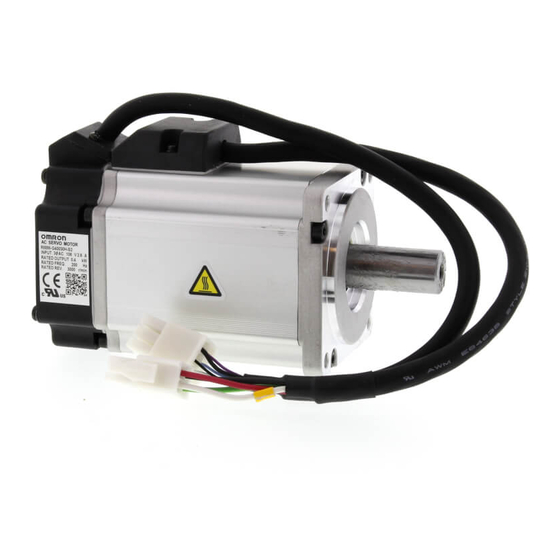
-
Contents
-
Table of Contents
-
Troubleshooting
-
Bookmarks
Quick Links
Cat. No. I562-E1-04
USER’S MANUAL
OMNUC G
SERIES
R88M-G@
(AC Servomotors)
R88D-GT@
(AC Servo Drives)
AC SERVOMOTORS/SERVO DRIVES
Related Manuals for Omron R88D-GT series
Summary of Contents for Omron R88D-GT series
-
Page 1
Cat. No. I562-E1-04 USER’S MANUAL OMNUC G SERIES R88M-G@ (AC Servomotors) R88D-GT@ (AC Servo Drives) AC SERVOMOTORS/SERVO DRIVES… -
Page 2
OMRON. No patent liability is assumed with respect to the use of the information contained herein. Moreover, because OMRON is constantly striving to improve its high-quality products, the information contained in this manual is subject to change without notice. -
Page 3
Introduction Introduction Thank you for choosing the OMNUC G Series. This User’s Manual describes installation/wiring methods and parameter setting procedures required for the operation of the OMNUC G Series as well as troubleshooting and inspection methods. Intended Readers This manual is intended for the following personnel. Those with knowledge of electrical systems (a qualified electrical engineer or the equivalent) as follows: •… -
Page 4
Omron’s exclusive warranty is that the Products will be free from defects in materials and workman- ship for a period of twelve months from the date of sale by Omron (or such other period expressed in writing by Omron). Omron disclaims all other warranties, express or implied. -
Page 5
Disclaimers Performance Data Data presented in Omron Company websites, catalogs and other materials is provided as a guide for the user in determining suitability and does not constitute a warranty. It may represent the result of Omron’s test conditions, and the user must correlate it to actual application requirements. Actual performance is subject to the Omron’s Warranty and Limitations of Liability. -
Page 6
Make sure that these protective covers and shields are put in place as specified before using the product. Consult your OMRON representative when using the product after a long period of storage. WARNING Always connect the frame ground terminals of the Servo Drive and the Servomotor to 100 Ω… -
Page 7
Precautions for Safe Use Installation, operation, maintenance, or inspection must be performed by authorized personnel. Not doing so may result in electric shock or injury. Wiring or inspection must not be performed for at least 15 minutes after turning OFF the power supply. -
Page 8
Precautions for Safe Use WARNING Do not place any flammable materials near the Servomotor, Servo Drive, or Regeneration Resistor. Doing so may result in fire. Mount the Servomotor, Servo Drive, and Regeneration Resistor on metal or other non- flammable materials. Failure to do so may result in fire. -
Page 9
Precautions for Safe Use Installation and Wiring Precautions Caution Do not step on or place a heavy object on the product. Doing so may result in injury. Do not cover the inlet or outlet ports and prevent any foreign objects from entering the product. -
Page 10
Precautions for Safe Use Operation and Adjustment Precautions Caution Confirm that no adverse effects will occur in the system before performing the test operation. Not doing so may result in equipment damage. Check the newly set parameters for proper operation before actually running them. Not doing so may result in equipment damage. -
Page 11
Precautions for Safe Use Warning Label Position Warning labels are located on the product as shown in the following illustration. Be sure to follow the instructions given there. Location of warning label (R88D-GT01H) Warning Label Contents Disposing of the Product •… -
Page 12
• No connectors or mounting screws are provided. They have to be prepared by the user. • Should you find any problems (missing parts, damage to the Servo Drive, etc.), please contact your local sales representative or OMRON sales office. Connector for main circuit… -
Page 13
Items to Check When Unpacking Understanding Servo Drive Model Numbers The model number provides information such as the Servo Drive type, the applicable Servomotor capacity, and the power supply voltage. R88D-GT01H OMNUC G-Series Servo Drive Drive Type T : Three-mode type Applicable Servomotor Capacity A5 : 50 W 01 : 100 W… -
Page 14
Items to Check When Unpacking Understanding Servomotor Model Numbers R88M-GP10030H-BOS2 G-Series Servomotor Motor Type Blank: Cylinder type Flat type Servomotor Capacity 050: 50 W 100: 100 W 200: 200 W 400: 400 W 750: 750 W 900: 900 W 1K0: 1 kW 1K5:… -
Page 15
Items to Check When Unpacking Understanding Decelerator Model Numbers (Backlash = 3′ Max.) R88G-HPG14A05100PBJ Decelerator for G-Series Servomotors Backlash = 3’ Max. Flange Size Number :@40 :@60 :@90 :@120 :@170 :@230 Gear Ratio :1/5 :1/9 (only frame number 11A) :1/11 (except frame number 65A) :1/12 (only frame number 65A) :1/20 (only frame number 65A) -
Page 16
Items to Check When Unpacking Understanding Decelerator Model Numbers (Backlash = 15′ Max.) R88G-VRSF09B100PCJ Decelerator for G-Series Servomotors Backlash = 15’ Max. Gear Ratio :1/5 :1/9 :1/15 :1/25 Flange Size Number :@52 :@78 :@98 Applicable Servomotor Capacity : 50 W :100 W :200 W :400 W… -
Page 17
LED displays and the countermeasures, error diagnoses Chapter 8 Troubleshooting based on the operation status and the countermeasures, and peri- odic maintenance. Provides examples of connections with OMRON PLCs and Posi- Chapter 9 Appendix tion Controllers, and the parameter tables. -
Page 18: Table Of Contents
Table of Contents Introduction ………………1 Terms and Conditions Agreement ……….. 2 Precautions for Safe Use…………..4 Items to Check When Unpacking ………… 10 About This Manual…………….15 Chapter 1 Features and System Configuration Overview………………. 1-1 System Configuration …………… 1-2 Names of Parts and Functions …………
-
Page 19: Table Of Contents
Table of Contents Chapter 5 Operating Functions Position Control…………….5-1 Speed Control ……………… 5-3 Internally Set Speed Control …………5-5 Torque Control …………….. 5-8 Switching the Control Mode …………. 5-11 Forward and Reverse Drive Prohibit ……….5-14 Encoder Dividing …………….5-15 Electronic Gear …………….
-
Page 20
Table of Contents… -
Page 21
Chapter 1 Features and System Configuration 1-1 Overview …………1-1 Overview of the G Series …………1-1 Features of the G Series…………1-1 1-2 System Configuration……… 1-2 1-3 Names of Parts and Functions ……1-3 Servo Drive Part Names …………1-3 Servo Drive Functions…………1-4 Forward and Reverse Motor Rotation ……..1-4 1-4 System Block Diagrams …….. -
Page 22: Overview
High-speed Response The G-Series AC Servomotors and Servo Drives have achieved high-speed response capabilities exceeding OMRON’s W-Series models, with a high-response frequency of 1 kHz (compared to 400 Hz for the W Series). Suppressing Vibration of Low-rigidity Mechanisms during Acceleration/…
-
Page 23: System Configuration
1-2 System Configuration 1-2 System Configuration Controller with Voltage Output SYSMAC CS-series Motion Control Unit Programmable CS1W-MC221/421(-V1) Analog voltage Controller Flexible Motion Controller OMNUC G-Series AC Servo Drive Pulse R88D-G@ string FQM1-MMA22 FQM1-MMP22 SYSMAC PLC and Position Control Unit with pulse output functions SYSMAC CJ/CS-series Position Control Unit CJ1W-NC113/213/413…
-
Page 24: Names Of Parts And Functions
1-3 Names of Parts and Functions 1-3 Names of Parts and Functions Servo Drive Part Names Display area Unit No. switch Settings area Analog monitor 1 check pin (IM) Check pin (G: GND) Analog monitor 2 check pin (SP) RS-485 Communications connector (CN3A) Main-circuit power terminals…
-
Page 25
1-3 Names of Parts and Functions Servo Drive Functions Display Area A 6-digit 7-segment LED display shows the Servo Drive status, alarm codes, parameters, and other information. Check Pins (IM, SP, and G) The actual Servomotor speed, command speed, torque, and number of accumulated pulses can be measured based on the analog voltage level by using an oscilloscope. -
Page 26: System Block Diagrams
1-4 System Block Diagrams 1-4 System Block Diagrams R88D-GTA5L/-GT01L/-GT02L/-GTA5H/-GT01H/-GT02H/-GT04H Voltage detec- tion SW power Current Relay Regene- Over- supply Gate drive detection rative current Main circuit drive control detection control Internal control Display/ MPU & ASIC power setting circuits supply Position, speed, and torque processor, PWM control Encoder…
-
Page 27
1-4 System Block Diagrams R88D-GT04L/-GT08H/-GT10H/-GT15H Internal regeneration resistor Voltage detec- tion SW power Regene- Over- Current supply Relay Gate drive rative current detection Main circuit drive control detection control Internal control Display/ MPU & ASIC power setting circuits Position, speed, and torque processor, supply PWM control Encoder… -
Page 28
1-4 System Block Diagrams R88D-GT20H Terminals Terminals Internal regeneration resistor SW power Regene- Current supply Relay Voltage Gate drive rative detection Main circuit drive detection control control Internal Display/ control MPU & ASIC setting circuits power Position, speed, and torque processor, supply PWM control Encoder… -
Page 29
1-4 System Block Diagrams R88D-GT30H/GT50H Terminals Terminals Internal regeneration resistor SW power Current Regene- supply Relay Voltage Gate drive rative detection Main circuit Gate drive detection control control Internal control Display/ MPU & ASIC power setting circuits Position, speed, and torque processor, supply PWM control Encoder… -
Page 30
1-4 System Block Diagrams R88D-GT75H Terminals Terminals SW power Regene- Current supply Relay Voltage Gate drive rative detection Main circuit Gate drive detection control control Internal control Display/ MPU & ASIC power setting circuits Position, speed, and torque processor, supply PWM control Encoder communications… -
Page 31: Applicable Standards
1-5 Applicable Standards 1-5 Applicable Standards EC Directives EC Directive Product Applicable standards Comments Safety requirements for electrical equipment for AC Servo Drive EN 50178 Low Voltage measurement, control, or laboratory use Directive AC Servomotor IEC 60034-1/-5 Rotating electrical machines Limits of radio disturbance and measurement EN 55011 Class A Group1 methods for industrial, scientific, and medical…
-
Page 32
1-5 Applicable Standards The Servo Drives and Servomotors comply with UL 508C (file No. E179149) as long as the following installation conditions 1 and 2 are met. Use the Servo Drive in a pollution degree 1 or 2 environment as defined in IEC 60664-1 (example: installation in an IP54 control panel). -
Page 33: External And Mounting Hole Dimensions
Chapter 2 Standard Models and Dimensions 2-1 Standard Models ……….2-1 Servo Drives ……………..2-1 Servomotors…………….2-2 Servo Drive-Servomotor Combinations ……..2-5 Decelerators…………….2-7 Accessories and Cables …………2-14 2-2 External and Mounting Hole Dimensions … 2-25 Servo Drives ……………..2-25 Servomotors…………….2-35 Parameter Unit Dimensions ……….2-45 Servomotor and Decelerator Combinations……2-46 Decelerator Dimensions…………2-49 External Regeneration Resistor Dimensions ……2-63…
-
Page 34
2-1 Standard Models 2-1 Standard Models Servo Drives Specifications Model 50 W R88D-GTA5L 100 W R88D-GT01L Single-phase 100 VAC 200 W R88D-GT02L 400 W R88D-GT04L 50 W R88D-GT01H 100 W Single-phase 200 VAC 200 W R88D-GT02H 400 W R88D-GT04H 750 W R88D-GT08H 1 kW R88D-GT10H… -
Page 35
2-1 Standard Models Servomotors 3,000-r/min Servomotors Model With incremental encoder With absolute encoder Specifications Straight shaft without Straight shaft with key Straight shaft without Straight shaft with key and tap and tap 50 W R88M-G05030H R88M-G05030H-S2 R88M-G05030T R88M-G05030T-S2 100 W R88M-G10030L R88M-G10030L-S2 R88M-G10030S R88M-G10030S-S2… -
Page 36
2-1 Standard Models 3,000-r/min Flat Servomotors Model With incremental encoder With absolute encoder Specifications Straight shaft without Straight shaft with key Straight shaft without Straight shaft with key and tap and tap 100 W R88M-GP10030L R88M-GP10030L-S2 R88M-GP10030S R88M-GP10030S-S2 100 V 200 W R88M-GP20030L R88M-GP20030L-S2 R88M-GP20030S… -
Page 37
2-1 Standard Models 1,000-r/min Servomotors Model With absolute encoder Specifications Straight shaft with key Straight shaft without key and tap 900 W R88M-G90010T R88M-G90010T-S2 2 kW R88M-G2K010T R88M-G2K010T-S2 With- 200 V 3 kW R88M-G3K010T R88M-G3K010T-S2 brake 4.5 kW R88M-G4K510T R88M-G4K510T-S2 6 kW R88M-G6K010T R88M-G6K010T-S2… -
Page 38
2-1 Standard Models Servo Drive-Servomotor Combinations The tables in this section show the possible combinations of OMNUC G-Series Servo Drives and Servomotors. The Servomotors and Servo Drives can only be used in the listed combinations. The box (-@) at the end of the model number is for options, such as the shaft type, brake and Decelerators. -
Page 39
2-1 Standard Models 2,000-r/min Servomotors and Servo Drives Servomotor Voltage Servo Drive Rated output With absolute encoder 1 kW R88M-G1K020T-@ R88D-GT10H Single-phase/ three-phase 200 V 1.5 kW R88M-G1K520T-@ R88D-GT15H 2 kW R88M-G2K020T-@ R88D-GT20H 3 kW R88M-G3K020T-@ R88D-GT30H Three-phase 4 kW R88M-G4K020T-@ R88D-GT50H 200 V… -
Page 40
2-1 Standard Models Decelerators The following types of Decelerators are available for OMNUC G-Series Servomotors. Select a Decelerator based on the Servomotor capacity. Backlash = 3’ Max. Decelerators for 3,000-r/min Servomotors Specifications Model Motor capacity Gear ratio R88G-HPG11B05100B@ R88G-HPG11B09050B@ 50 W 1/21 R88G-HPG14A21100B@… -
Page 41
2-1 Standard Models Specifications Model Motor Gear ratio capacity R88G-HPG32A051K0B 1/11 R88G-HPG32A111K0B 1 kW 1/21 R88G-HPG32A211K0B 1/33 R88G-HPG32A331K0B 1/45 R88G-HPG50A451K0B R88G-HPG32A052K0B 1/11 R88G-HPG32A112K0B 1.5 kW 1/21 R88G-HPG32A211K5B 1/33 R88G-HPG50A332K0B 1/45 R88G-HPG50A451K5B R88G-HPG32A052K0B 1/11 R88G-HPG32A112K0B 2 kW 1/21 R88G-HPG50A212K0B 1/33 R88G-HPG50A332K0B R88G-HPG32A053K0B 3 kW 1/11… -
Page 42
2-1 Standard Models Decelerators for 2,000-r/min Servomotors Specifications Model Motor Gear ratio capacity R88G-HPG32A053K0B 1/11 R88G-HPG32A112K0SB 1 kW 1/21 R88G-HPG32A211K0SB 1/33 R88G-HPG50A332K0SB 1/45 R88G-HPG50A451K0SB R88G-HPG32A053K0B 1/11 R88G-HPG32A112K0SB 1.5 kW 1/21 R88G-HPG50A213K0B 1/33 R88G-HPG50A332K0SB R88G-HPG32A053K0B 1/11 R88G-HPG32A112K0SB 2 kW 1/21 R88G-HPG50A213K0B 1/33 R88G-HPG50A332K0SB R88G-HPG32A054K0B… -
Page 43
2-1 Standard Models Decelerators for 1,000-r/min Servomotors Specifications Model Motor Gear ratio capacity R88G-HPG32A05900TB 1/11 R88G-HPG32A11900TB 900 W 1/21 R88G-HPG50A21900TB 1/33 R88G-HPG50A33900TB R88G-HPG32A052K0TB 1/11 R88G-HPG50A112K0TB 2 kW 1/21 R88G-HPG50A212K0TB 1/25 R88G-HPG65A255K0SB R88G-HPG50A055K0SB 1/11 R88G-HPG50A115K0SB 3 kW 1/20 R88G-HPG65A205K0SB 1/25 R88G-HPG65A255K0SB R88G-HPG50A054K5TB 4.5 kW 1/12… -
Page 44
2-1 Standard Models Decelerators for 3,000-r/min Flat Servomotors Specifications Model Motor capacity Gear ratio R88G-HPG11B05100PB@ 1/11 R88G-HPG14A11100PB@ 100 W 1/21 R88G-HPG14A21100PB@ 1/33 R88G-HPG20A33100PB@ 1/45 R88G-HPG20A45100PB@ R88G-HPG14A05200PB@ 1/11 R88G-HPG20A11200PB@ 200 W 1/21 R88G-HPG20A21200PB@ 1/33 R88G-HPG20A33200PB@ 1/45 R88G-HPG20A45200PB@ R88G-HPG20A05400PB@ 1/11 R88G-HPG20A11400PB@ 400 W 1/21 R88G-HPG20A21400PB@ 1/33… -
Page 45
2-1 Standard Models Backlash = 15’ Max. Decelerators for 3,000-r/min Servomotors (Straight Shaft with Key) Specifications Model Motor capacity Gear ratio R88G-VRSF05B100CJ R88G-VRSF09B100CJ 50 W 1/15 R88G-VRSF15B100CJ 1/25 R88G-VRSF25B100CJ R88G-VRSF05B100CJ R88G-VRSF09B100CJ 100 W 1/15 R88G-VRSF15B100CJ 1/25 R88G-VRSF25B100CJ R88G-VRSF05B200CJ R88G-VRSF09C200CJ 200 W 1/15 R88G-VRSF15C200CJ… -
Page 46
2-1 Standard Models Decelerators for 3,000-r/min Flat Servomotors (Straight Shaft with Key) Specifications Model Motor capacity Gear ratio R88G-VRSF05B100PCJ R88G-VRSF09B100PCJ 100 W 1/15 R88G-VRSF15B100PCJ 1/25 R88G-VRSF25B100PCJ R88G-VRSF05B200PCJ R88G-VRSF09C200PCJ 200 W 1/15 R88G-VRSF15C200PCJ 1/25 R88G-VRSF25C200PCJ R88G-VRSF05C400PCJ R88G-VRSF09C400PCJ 400 W 1/15 R88G-VRSF15C400PCJ 1/25 R88G-VRSF25C400PCJ 2-13… -
Page 47
2-1 Standard Models Accessories and Cables Encoder Cables (Standard Cables) Specifications Model R88A-CRGA003C R88A-CRGA005C 10 m R88A-CRGA010C 3,000-r/min Servomotors of 50 to 750 W with an absolute encoder, 15 m R88A-CRGA015C 3,000-r/min Flat Servomotors of 100 to 400 W with an absolute 20 m R88A-CRGA020C encoder… -
Page 48
2-1 Standard Models Servomotor Power Cables (Standard Cables) Model Specifications For Servomotor without For Servomotor with brake brake R88A-CAGA003S R88A-CAGA005S 10 m R88A-CAGA010S 3,000-r/min Servomotors of 50 to 750 W, 15 m R88A-CAGA015S 3,000-r/min Flat Servomotors of 100 to 20 m R88A-CAGA020S 400 W… -
Page 49
2-1 Standard Models Model Specifications For Servomotor without For Servomotor with brake brake R88A-CAGE003S R88A-CAGE005S 10 m R88A-CAGE010S 15 m R88A-CAGE015S 1,500-r/min Servomotors of 7.5 kW, 1,000-r/min Servomotors of 6 kW 20 m R88A-CAGE020S 30 m R88A-CAGE030S 40 m R88A-CAGE040S 50 m R88A-CAGE050S Note There are separate connectors for power and brakes for 3,000-r/min Servomotors of 50 to… -
Page 50
2-1 Standard Models Brake Cables (Standard Cables) Specifications Model R88A-CAGA003B R88A-CAGA005B 10 m R88A-CAGA010B 15 m R88A-CAGA015B 3,000-r/min Servomotors of 50 to 750 W, 3,000-r/min Flat Servomotors of 100 to 400 W 20 m R88A-CAGA020B 30 m R88A-CAGA030B 40 m R88A-CAGA040B 50 m R88A-CAGA050B… -
Page 51
2-1 Standard Models Encoder Cables (Robot Cables) Specifications Model R88A-CRGA003CR R88A-CRGA005CR 10 m R88A-CRGA010CR 3,000-r/min Servomotors of 50 to 750 W 15 m R88A-CRGA015CR with an absolute encoder, 3,000-r/min Flat Servomotors of 100 to 400 W 20 m R88A-CRGA020CR with an absolute encoder 30 m R88A-CRGA030CR… -
Page 52
2-1 Standard Models Servomotor Power Cables (Robot Cables) Model Specifications For Servomotor without For Servomotor with brake brake R88A-CAGA003SR R88A-CAGA005SR 10 m R88A-CAGA010SR 3,000-r/min Servomotors of 50 to 750 W, 15 m R88A-CAGA015SR 3,000-r/min Flat Servomotors of 20 m R88A-CAGA020SR 100 to 400 W 30 m… -
Page 53
2-1 Standard Models Brake Cables (Robot Cables) Specifications Model R88A-CAGA003BR R88A-CAGA005BR 10 m R88A-CAGA010BR 15 m R88A-CAGA015BR 3,000-r/min Servomotors of 50 to 750 W, 3,000-r/min Flat Servomotors of 100 to 400 W 20 m R88A-CAGA020BR 30 m R88A-CAGA030BR 40 m R88A-CAGA040BR 50 m R88A-CAGA050BR… -
Page 54
2-1 Standard Models Servo Relay Units (for CN1) Specifications Model For CS1W-NC113/-NC133 For CJ1W-NC113/-NC133 XW2B-20J6-1B For C200HW-NC113 For CS1W-NC213/-NC413/-NC233/-NC433 For CJ1W-NC213/-NC413/-NC233/-NC433 XW2B-40J6-2B For C200HW-NC213/-NC413 Servo Relay Units XW2B-20J6-8A For CJ1M-CPU21/-CPU22/-CPU23 XW2B-40J6-9A For FQM1-MMA22 XW2B-80J7-12A For FQM1-MMP22 For CQM1-CPU43-V1 XW2B-20J6-3B … -
Page 55
2-1 Standard Models Servo Relay Unit Cables for Position Control Units Specifications Model 0.5 m XW2Z-050J-A3 For CQM1-CPU43-V1 (XW2B-20J6-3B) XW2Z-100J-A3 0.5 m XW2Z-050J-A6 For CS1W-NC113, C200HW-NC113 (XW2B-20J6-1B) XW2Z-100J-A6 0.5 m XW2Z-050J-A7 For CS1W-NC213/-NC413, C200HW-NC213/ -NC413 (XW2B-20J6-2B) XW2Z-100J-A7 0.5 m XW2Z-050J-A10 For CS1W-NC133 (XW2B-20J6-1B) XW2Z-100J-A10… -
Page 56
2-1 Standard Models Control Cables Specifications Model R88A-CPG001M1 R88A-CPG002M1 Motion Control Unit Cables for 1 axis CS1W-MC221-V1/-MC421-V1 R88A-CPG003M1 R88A-CPG005M1 R88A-CPG001M2 R88A-CPG002M2 Motion Control Unit Cables for 2 axes CS1W-MC221-V1/-MC421-V1 R88A-CPG003M2 R88A-CPG005M2 R88A-CPG001S General-purpose Control Cables with Connector on One End R88A-CPG002S XW2Z-100J-B24 Connector-Terminal Block Cables… -
Page 57
2-1 Standard Models Mounting Brackets (L Brackets for Rack Mounting) Specifications Model R88D-GTA5L/-GT01L/-GT01H/-GT02H R88A-TK01G R88D-GT02L/-GT04H R88A-TK02G R88D-GT04L/-GT08H R88A-TK03G R88D-GT10H/-GT15H R88A-TK04G Absolute Encoder Backup Battery Specifications Model 2,000 mA·h 3.6 V R88A-BAT01G 2-24… -
Page 58
2-2 External and Mounting Hole Dimensions 2-2 External and Mounting Hole Dimensions Servo Drives Single-phase 100 VAC: R88D-GTA5L/-GT01L (50 to 100 W) Single-phase 200 VAC: R88D-GT01H/-GT02H (50 to 200 W) Wall Mounting External Dimensions Mounting Hole Dimensions Two, M4 AC SERVO DRIVER UNIT No. -
Page 59
2-2 External and Mounting Hole Dimensions Front Panel Mounting (Using Mounting Brackets) External Dimensions Mounting Hole Dimensions (Reference) Two, M4 5.2 dia. Square hole R2.6 (42)* * The dimensions of the square hole are reference values. Dimensions for front panel mounting are references values that provide leeway. 2-26… -
Page 60
2-2 External and Mounting Hole Dimensions Single-phase 100 VAC: R88D-GT02L (200 W) Single-phase 200 VAC: R88D-GT04H (400 W) Wall Mounting External Dimensions Mounting Hole Dimensions Two, M4 AC SERVO DRIVER UNIT No. DATA Front Panel Mounting (Using Mounting Brackets) External Dimensions Mounting Hole Dimensions (Reference) Two, M4… -
Page 61
2-2 External and Mounting Hole Dimensions Single-phase 100 VAC: R88D-GT04L (400 W) Single-phase/Three-phase 200 VAC: R88D-GT08H (750 W) Wall Mounting External Dimensions Mounting Hole Dimensions Two, M4 AC SERVO DRIVER UNIT No. DATA Front Panel Mounting (Using Mounting Brackets) External Dimensions Mounting Hole Dimensions (Reference) Two, M4… -
Page 62
2-2 External and Mounting Hole Dimensions Single-phase/Three-phase 200 VAC: R88D-GT10H/-GT15H (900 W to 1.5 kW) Wall Mounting External Dimensions Mounting Hole Dimensions Two, M4 AC SERVO DRIVER UNIT No. DATA Front Panel Mounting (Using Mounting Brackets) External Dimensions Mounting Hole Dimensions (Reference) Four, M4 5.2 dia. -
Page 63
2-2 External and Mounting Hole Dimensions Three-phase 200 VAC: R88D-GT20H (2 kW) Wall Mounting External Dimensions 17.5 42.5 R2.6 R2.6 dia. AC SERVO DRIVER UNIT No. DATA R2.6 R2.6 dia. 42.5 17.5 Mounting Hole Dimensions Four, M4 17.5 2-30… -
Page 64
2-2 External and Mounting Hole Dimensions Front Panel Mounting (Using Mounting Brackets) External Dimensions 17.5 42.5 R2.6 R2.6 dia. AC SERVO DRIVER UNIT No. DATA R2.6 R2.6 dia. 42.5 17.5 Mounting Hole Dimensions (Reference) Four, M4 Square hole 20.5 (89)* * The dimensions of the square hole are reference values. -
Page 65
2-2 External and Mounting Hole Dimensions Three-phase 200 VAC: R88D-GT30H/-GT50H (2 to 5 kW) Wall Mounting External Dimensions R2.6 R2.6 5.2 dia. AC SERVO DRIVER UNIT No. DATA R2.6 R2.6 dia. Mounting Hole Dimensions Six, M4 2-32… -
Page 66
2-2 External and Mounting Hole Dimensions Front Panel Mounting (Using Mounting Brackets) External Dimensions 32.3 R2.6 5.2 dia. R2.6 AC SERVO DRIVER UNIT No. DATA R2.6 R2.6 dia. Mounting Hole Dimensions (Reference) Six, M4 Square hole (132)* * The dimensions of the square hole are reference values. -
Page 67
2-2 External and Mounting Hole Dimensions Three-phase 200 VAC: R88D-GT75H (7.5 kW) Front Panel Mounting (Using Mounting Brackets) External Dimensions 37.5 339.3 82.5 45.1 (2.3) Four, 5.2 dia. Mounting Hole Dimensions (Reference) Six, M4 Square hole * The dimensions of the square hole are reference values. -
Page 68
2-2 External and Mounting Hole Dimensions Servomotors 3,000-r/min Servomotors 50 W/100 W R88M-G05030H(-S2)/-G10030L(-S2)/-G10030H(-S2)/-G05030H-B(S2) /-G10030L-B(S2)/-G10030H-B(S2) R88M-G05030T(-S2)/-G10030S(-S2)/-G10030T(-S2)/-G05030T-B(S2) /-G10030S-B(S2)/-G10030T-B(S2) Brake connector Encoder Motor connector connector (Dimensions of shaft end with key and tap) 40 × 40 12.5 Three, h: 9 M3 (depth: 6) Two, 4.3 dia. -
Page 69
2-2 External and Mounting Hole Dimensions 3,000-r/min Servomotors 200 W/400 W/750 W R88M-G20030L(-S2)/-G40030L(-S2)/-G20030H(-S2)/-G40030H(-S2) /-G75030H(-S2)/-G20030L-B(S2)/-G40030L-B(S2) /-G20030H-B(S2)/-G40030H-B(S2)/-G75030H-B(S2) R88M-G20030S(-S2)/-G40030S(-S2)/-G20030T(-S2)/-G40030T(-S2) /-G75030T(-S2)/-G20030S-B(S2)/-G40030S-B(S2) /-G20030T-B(S2)/-G40030T-B(S2)/-G75030T-B(S2) Brake connector Encoder Motor connector connector (Dimensions of shaft end with key and tap) Four, Z dia. C × C M(effective depth: L) Dimensions (mm) Model LR S D1 D2 C… -
Page 70
2-2 External and Mounting Hole Dimensions 3,000-r/min Servomotors 1 kW/1.5 kW/2 kW R88M-G1K030T(-S2)/-G1K530T(-S2)/-G2K030T(-S2)/-G1K030T-B(S2) /-G1K530T-B(S2)/-G2K030T-B(S2) Servomotor (Dimensions of shaft end canon plug C × C with key and tap) Encoder canon plug Four, Z dia. Six, h: 9 M5 (depth: 12) Dimensions (mm) Model LL D1 D2… -
Page 71
2-2 External and Mounting Hole Dimensions 3,000-r/min Servomotors 4 kW/5 kW R88M-G4K030T(-S2)/-G5K030T(-S2)/-G4K030T-B(S2)/-G5K030T-B(S2) Servomotor/brake connector (Dimensions of shaft end 130×130 Encoder with key and tap) connector Four, 9 dia. Eight, h: 9 M8 (depth: 20) 145 dia. Dimensions (mm) Model R88M-G4K030@ R88M-G5K030@ R88M-G4K030@-B@… -
Page 72
2-2 External and Mounting Hole Dimensions 3,000-r/min Flat Servomotors 100 W/200 W/400 W R88M-GP10030L(-S2)/-GP20030L(-S2)/-GP40030L(-S2)/-GP10030H(-S2) /-GP20030H(-S2)/-GP40030H(-S2)/-GP10030L-B(S2)/-GP20030L-B(S2) /-GP40030L-B(S2)/-GP10030H-B(S2)/-GP20030H-B(S2)/-GP40030H-B(S2) R88M-GP10030S(-S2)/-GP20030S(-S2)/-GP40030S(-S2)/-GP10030T(-S2) /-GP20030T(-S2)/-GP40030T(-S2)/-GP10030S-B(S2)/-GP20030S-B(S2) /-GP40030S-B(S2)/-GP10030T-B(S2)/-GP20030T-B(S2)/-GP40030T-B(S2) Encoder connector Motor connector Brake connector C × C (Dimensions of shaft end Four, Z dia. with key and tap) M (depth: L) Dimensions (mm) Model… -
Page 73
2-2 External and Mounting Hole Dimensions 2,000-r/min Servomotors 1 kW/1.5 kW R88M-G1K020T(-S2)/-G1K520T(-S2)/-G1K020T-B(S2)/-G1K520T-B(S2) Servomotor/brake (Dimensions of shaft end connector 130 × 130 with key and tap) Encoder connector Four, 9 dia. Eight, h: 9 M5 (depth: 12) Dimensions (mm) Model R88M-G1K020@ R88M-G1K520@ R88M-G1K020@-B@… -
Page 74
2-2 External and Mounting Hole Dimensions 2,000-r/min Servomotors 4 kW/5 kW R88M-G4K020T(-S2)/-G5K020T(-S2)/-G4K020T-B(S2)/-G5K020T-B(S2) Servomotor/brake connector C × C (Dimensions of shaft end Encoder with key and tap) connector Four, Z dia. M (depth: L) Dimensions (mm) Model LL LR D3 KL1 242 65 28 165 130 150 190 128 11 51 8h9… -
Page 75
2-2 External and Mounting Hole Dimensions 1,500-r/min Servomotors 7.5 kW R88M-G7K515T(-S2)/-G7K515T-B(S2) Brake connector (Dimensions of shaft end Motor Eye-bolt connector with key and tap) Nominal diameter: 10 176 × 176 Encoder 12, h: 9 24 3.2 Four, 13.5 dia. connector M16 (depth:32) Dimensions (mm) -
Page 76
2-2 External and Mounting Hole Dimensions 1,000-r/min Servomotors 900 W/2 kW R88M-G90010T(-S2)/-G2K010T(-S2)/-G90010T-B(S2)/-G2K010T-B(S2) Encoder connector Servomotor/brake connector (Dimensions of shaft end C × C with key and tap) Four, Z dia. M (depth: L) Dimensions (mm) Model LL LR G KL1 175 70 22 145 110 130 165 12 118… -
Page 77
2-2 External and Mounting Hole Dimensions 1,000-r/min Servomotors 4.5 kW R88M-G4K510T(-S2)/-G4K510T-B(S2) (Dimensions of shaft end Servomotor/brake with key and tap) connector 176 × 176 Eye-bolt Nominal 12, h: 9 24 3.2 diameter: 10 Encoder connector Four, 13.5 dia. M16 (depth: 32) Dimensions (mm) Model 300.5… -
Page 78
2-2 External and Mounting Hole Dimensions Parameter Unit Dimensions R88A-PR02G Hand-held Parameter Unit (62) (24) M3 (depth: 5) (15) Mini DIN 8-pin (1500) MD connector 2-45… -
Page 79
2-2 External and Mounting Hole Dimensions Servomotor and Decelerator Combinations 000-r/min Servomotors 1/11 Motor model (1/9 for flange size 1/21 1/33 1/45 No.11) R88G- R88G- R88G- R88M- HPG11B05100B HPG14A21100B R88G- R88G- HPG11B09050B G05030 (Also used with (Also used with HPG14A33050B HPG14A45050B (Gear ratio 1/9) R88M-G10030… -
Page 80
2-2 External and Mounting Hole Dimensions 3,000-r/min Flat Servomotors Motor 1/11 1/21 1/33 1/45 model R88M- R88G- R88G- R88G- R88G- R88G- GP10030 HPG11B05100PB HPG14A11100PB HPG14A21100PB HPG20A33100PB HPG20A45100PB R88M- R88G- R88G- R88G- R88G- R88G- GP20030 HPG14A05200PB HPG20A11200PB HPG20A21200PB HPG20A33200PB HPG20A45200PB R88M- R88G- R88G- R88G-… -
Page 81
2-2 External and Mounting Hole Dimensions 1,000-r/min Servomotors 1/11 1/21 1/33 Motor model (1/12 for flange size (1/20 for flange size (1/25 for flange size No.65) No.65) No.65) R88M- R88G- R88G- R88G- R88G- G90010T HPG32A05900TB HPG32A11900TB HPG50A21900TB HPG50A33900TB R88G- R88M- R88G- R88G- R88G-… -
Page 82
2-2 External and Mounting Hole Dimensions Decelerator Dimensions Backlash = 3’ Max. Decelerators for 3,000-r/min Servomotors Dimensions (mm) Model 1/5 R88G-HPG11B05100B@ 39.5 40 40×40 46 40.0 39.5 1/9 R88G-HPG11B09050B@ 39.5 40 40×40 46 40.0 39.5 50 W 1/21 R88G-HPG14A21100B@ 64.0 60 60×60 70 56.0 55.5 1/33 R88G-HPG14A33050B@ 64.0… -
Page 83
2-2 External and Mounting Hole Dimensions Dimensions (mm) Model 1/5 R88G-HPG14A05400B@ 64.0 60×60 56.0 55.5 1/11 R88G-HPG20A11400B@ 71.0 89 dia. 105 85.0 84.0 400 W 1/21 R88G-HPG20A21400B@ 71.0 89 dia. 105 85.0 84.0 1/33 R88G-HPG32A33400B@ 104.0 133 120 122 dia. 135 70 115.0 114.0 84 98 12.5 35 1/45 R88G-HPG32A45400B@ 104.0 133 120 122 dia. -
Page 84
2-2 External and Mounting Hole Dimensions Dimensions (mm) Model 104 133 120 122 dia. 135 100 115 114 1/5 R88G-HPG32A051K0B 98 12.5 35 104 133 120 122 dia. 135 100 115 114 1/11 R88G-HPG32A111K0B 98 12.5 35 104 133 120 122 dia. 135 100 115 114 1 kW 1/21 R88G-HPG32A211K0B 98 12.5 35… -
Page 85
2-2 External and Mounting Hole Dimensions Dimensions (mm) Model Key dimensions dimensions 1/5 R88G-HPG32A051K0B M6×12 5.0 M10 1/11 R88G-HPG32A111K0B M6×12 5.0 M10 1 kW 1/21 R88G-HPG32A211K0B M6×12 5.0 M10 1/33 R88G-HPG32A331K0B M6×12 5.0 M10 1/45 R88G-HPG50A451K0B M6×10 5.5 M10 1/5 R88G-HPG32A052K0B M8×10 5.0 M10 1/11 R88G-HPG32A112K0B… -
Page 86
2-2 External and Mounting Hole Dimensions Decelerators for 2,000-r/min Servomotors Dimensions (mm) Model × 1/5 R88G-HPG32A053K0B 107 133 120 130 130 135 145 115 114 98 12.5 35 × 1/11 R88G-HPG32A112K0SB 107 133 120 130 130 135 145 115 114 98 12.5 35 ×… -
Page 87
2-2 External and Mounting Hole Dimensions Dimensions (mm) Model 1/5 R88G-HPG50A054K0SB 149 156 170 180×180 190 165 165 163 122 103 12.0 53 1/11 R88G-HPG50A114K0SB 149 156 170 180×180 190 165 165 163 122 103 12.0 53 4 kW 1/20 R88G-HPG65A204K0SB 231 222 230 180×180 260 165 220 214 168 165 12.0 57 1/25 R88G-HPG65A254K0SB 231 222 230 180×180 260 165 220 214 168 165 12.0 57… -
Page 88
2-2 External and Mounting Hole Dimensions Decelerators for 1,000-r/min Servomotors Dimensions (mm) Model 1/5 R88G-HPG32A05900TB 133 120 130×130 135 145 115 114 98 12.5 35 1/11 R88G-HPG32A11900TB 133 120 130×130 135 145 115 114 98 12.5 35 900 W 1/21 R88G-HPG50A21900TB 156 170 130×130 190 145 165 163 122 103 12.0 53 1/33 R88G-HPG50A33900TB 156 170 130×130 190 145 165 163 122 103 12.0 53… -
Page 89
2-2 External and Mounting Hole Dimensions Dimensions (mm) Model Key dimensions dimensions 1/5 R88G-HPG32A05900TB M8×25 5.0 M10 1/11 R88G-HPG32A11900TB M8×25 5.0 M10 900 W 1/21 R88G-HPG50A21900TB M8×25 5.5 M10 1/33 R88G-HPG50A33900TB M8×25 5.5 M10 1/5 R88G-HPG32A052K0TB 11 M12×25 5.0 M10 1/11 R88G-HPG50A112K0TB 14 M12×25 5.5 M10… -
Page 90
2-2 External and Mounting Hole Dimensions Decelerators for 3,000-r/min Flat Servomotors Dimensions (mm) Model 1/5 R88G-HPG11B05100PB@ 39.5 60×60 40.0 39.5 1/11 R88G-HPG14A11100PB@ 64.0 60×60 56.0 55.5 100 W 1/21 R88G-HPG14A21100PB@ 64.0 60×60 56.0 55.5 1/33 R88G-HPG20A33100PB@ 71.0 89 dia. 105 85.0 84.0 1/45 R88G-HPG20A45100PB@ 71.0 89 dia. -
Page 91
2-2 External and Mounting Hole Dimensions Dimensions (mm) Model 1/5 R88G-HPG20A05400PB@ 78.0 80×80 85.0 84.0 1/11 R88G-HPG20A11400PB@ 78.0 80×80 85.0 84.0 400 W 1/21 R88G-HPG20A21400PB@ 78.0 80×80 85.0 84.0 1/33 R88G-HPG32A33400PB@ 104.0 133 120 122 dia. 135 90 115.0 114.0 84 12.5 1/45 R88G-HPG32A45400PB@ 104.0 133 120 122 dia. -
Page 92
2-2 External and Mounting Hole Dimensions Backlash = 15’ Max. Decelerators for 3,000-r/min Servomotors Dimensions (mm) Model 1/5 R88G-VRSF05B100CJ 67.5 1/9 R88G-VRSF09B100CJ 67.5 50 W 1/15 R88G-VRSF15B100CJ 78.0 1/25 R88G-VRSF25B100CJ 78.0 1/5 R88G-VRSF05B100CJ 67.5 1/9 R88G-VRSF09B100CJ 67.5 100 W 1/15 R88G-VRSF15B100CJ 78.0 1/25 R88G-VRSF25B100CJ 78.0 1/5 R88G-VRSF05B200CJ 72.5… -
Page 93
2-2 External and Mounting Hole Dimensions Dimensions (mm) Model Key dimensions 1/5 R88G-VRSF05B100CJ 12 1/9 R88G-VRSF09B100CJ 12 50 W 1/15 R88G-VRSF15B100CJ 12 1/25 R88G-VRSF25B100CJ 12 1/5 R88G-VRSF05B100CJ 12 1/9 R88G-VRSF09B100CJ 12 100 W 1/15 R88G-VRSF15B100CJ 12 1/25 R88G-VRSF25B100CJ 12 1/5 R88G-VRSF05B200CJ 12 1/9 R88G-VRSF09C200CJ 19 200 W 1/15 R88G-VRSF15C200CJ 19… -
Page 94
2-2 External and Mounting Hole Dimensions Decelerators for 3,000-r/min Flat Servomotors Dimensions (mm) Model 1/5 R88G-VRSF05B100PCJ 67.5 1/9 R88G-VRSF09B100PCJ 67.5 100 W 1/15 R88G-VRSF15B100PCJ 78.0 1/25 R88G-VRSF25B100PCJ 78.0 1/5 R88G-VRSF05B200PCJ 72.5 1/9 R88G-VRSF09C200PCJ 89.5 200 W 1/15 R88G-VRSF15C200PCJ 100.0 50 1/25 R88G-VRSF25C200PCJ 100.0 50 1/5 R88G-VRSF05C400PCJ 89.5 1/9 R88G-VRSF09C400PCJ 89.5… -
Page 95
2-2 External and Mounting Hole Dimensions Dimensions (mm) Model Key dimensions 1/5 R88G-VRSF05B100PCJ 12 1/9 R88G-VRSF09B100PCJ 12 100 W 1/15 R88G-VRSF15B100PCJ 12 1/25 R88G-VRSF25B100PCJ 12 1/5 R88G-VRSF05B200PCJ 12 1/9 R88G-VRSF09C200PCJ 19 200 W 1/15 R88G-VRSF15C200PCJ 19 1/25 R88G-VRSF25C200PCJ 19 1/5 R88G-VRSF05C400PCJ 19 1/9 R88G-VRSF09C400PCJ 19 400 W 1/15 R88G-VRSF15C400PCJ 19… -
Page 96
2-2 External and Mounting Hole Dimensions External Regeneration Resistor Dimensions External Regeneration Resistor R88A-RR08050S/-RR080100S Thermal switch output t1.2 R88A-RR22047S1 Thermal switch output t1.2 R88A-RR50020S 2-63… -
Page 97
2-2 External and Mounting Hole Dimensions Reactor Dimensions 3G3AX-DL2002 Two, M4 Ground terminal (M4) Four, 5.2 × 8 3G3AX-DL2004 Two, M4 Ground terminal (M4) Four, 5.2 × 8 2-64… -
Page 98
2-2 External and Mounting Hole Dimensions 3G3AX-DL2007 Two, M4 Ground terminal (M4) Four, 5.2 × 8 3G3AX-DL2015 Two, M4 Ground terminal (M4) Four, 5.2 × 8 2-65… -
Page 99
2-2 External and Mounting Hole Dimensions 3G3AX-DL2022 Two, M4 Ground terminal (M4) Four, 6 × 9 3G3AX-AL2025/-AL2055 Ground terminal (M5) Six, M4 terminal screws Terminal block Ro R So S To T Ro R So S To Connection Diagram Four, 6 dia. -
Page 100
2-2 External and Mounting Hole Dimensions 3G3AX-AL2110/-AL2220 Terminal holes: Six, K dia. Ro R So S To R So S To Connection Diagram X±1 Y±1 Four, 6 dia. W=Terminal width (Notch) Ground terminal (M6) Dimensions (mm) Model 3G3AX-AL2110 150 103 70 170 108 60 80 5.3 3G3AX-AL2220 180 113 75 190 140 90… -
Page 101
Chapter 3 Specifications 3-1 Servo Drive Specifications ……… 3-1 General Specifications …………3-1 Characteristics …………..3-2 Main Circuit and Servomotor Connections ……3-6 Control I/O Connector Specifications (CN1) ……3-9 Control Input Circuits …………3-17 Control Input Details ………….3-20 Control Output Circuits…………3-26 Control Output Details…………3-27 Encoder Connector Specifications (CN2) ……3-30 Parameter Unit Connector Specifications (CN3B) ….3-31 3-2 Servomotor Specifications ……… -
Page 102: Servo Drive Specifications
3-1 Servo Drive Specifications 3-1 Servo Drive Specifications Select the Servo Drive matching the Servomotor to be used. (For details, refer to Servo Drive- Servomotor Combinations on page 2-5.) The same OMNUC G-Series Servo Drive can be used for either a pulse string input or analog input. You can change the control mode according to the Controller.
-
Page 103
3-1 Servo Drive Specifications Characteristics Servo Drives with 100-VAC Input Power Item R88D-GTA5L R88D-GT01L R88D-GT02L R88D-GT04L Continuous output current (rms) 1.3 A 1.8 A 2.4 A 4.9 A Momentary maximum output current (rms) 3.9 A 5.4 A 7.2 A 14.7 A Power supply… -
Page 104
3-1 Servo Drive Specifications Servo Drives with Single-phase 200-VAC Input Power R88D- R88D- R88D- R88D- R88D- R88D- Item GT01H GT02H GT04H GT08H GT10H GT15H Continuous output current (rms) 1.16 A 1.6 A 2.7 A 4.0 A 5.9 A 9.8 A Momentary maximum output current (rms) 3.5 A 5.3 A… -
Page 105
3-1 Servo Drive Specifications Servo Drives with Three-phase 200-VAC Input Power Item R88D-GT20H R88D-GT30H R88D-GT50H R88D-GT75H Continuous output current (rms) 14.3 A 17.4 A 31.0 A 45.4 A Momentary maximum output current 45.3 A 63.6 A 84.8 A 170.0 A (rms) Power supply… -
Page 106
3-1 Servo Drive Specifications Protective Functions Error detection Description The voltage between P and N in the control voltage converter has dropped below the spec- Control power supply undervoltage ified value. Overvoltage The voltage between P and N in the converter has exceeded the specified value. The main power supply between L1−L3 was interrupted for longer than the time set in the Momentary Hold Time (Pn6D) when the Undervoltage Alarm Selection (Pn65) was set to 1. -
Page 107
3-1 Servo Drive Specifications Main Circuit and Servomotor Connections When wiring the main circuit, use proper wire sizes, grounding systems, and anti-noise measures. R88D-GTA5L/-GT01L/-GT02L/-GT04L R88D-GT01H/-GT02H/-GT04H/-GT08H/-GT10H/-GT15H Main Circuit Connector Specifications (CNA) Name Function Symbol R88D-GT@L (50 W to 400 W): Single-phase 100 to 115 VAC (85 to 127 V), 50/60 Hz Main circuit power… -
Page 108
3-1 Servo Drive Specifications R88D-GT20H/-GT30H/-GT50H Main Circuit Terminal Block Specifications Symbol Name Function Main circuit power R88D-GT H (2 to 5 kW): Three-phase 200 to 230 VAC (170 to 253 V), 50/60Hz supply input Control circuit R88D-GT H: Single-phase 200 to 230 VAC (170 to 253V), 50/60 Hz power supply input External 2 to 5 kW: Normally B2 and B3 are connected. -
Page 109
3-1 Servo Drive Specifications R88D-GT75H Main Circuit Terminal Block Specifications (TB1) Symbol Name Function Main circuit power R88D-GT75H (6 to 7.5 kW): Three-phase 200 to 230 VAC (170 to 253 V), supply input 50/60Hz External 6 kW, 7.5 kW: A regeneration resistor is not built in. Regeneration Connect an External Regeneration Resistor between B1 and B2, Resistor connection… -
Page 110
3-1 Servo Drive Specifications Control I/O Connector Specifications (CN1) Control I/O Signal Connections and External Signal Processing for Position Control Reverse pulse 500 kpps max. Maximum Brake Interlock operating voltage: Forward 30 VDC pulse Maximum Servo Ready Output output current: Reverse 50 mA DC… -
Page 111
3-1 Servo Drive Specifications Control I/O Signal Connections and External Signal Processing for Speed Control BKIR Speed Command Input Maximum Brake Interlock operating BKIRCOM AGND voltage: Forward Torque 30 VDC READY Limit Input Maximum Servo Ready Output output READYCOM AGND current: Reverse Torque… -
Page 112
3-1 Servo Drive Specifications Control I/O Signal Connections and External Signal Processing for Torque Control Torque Command Input or Speed Limit BKIR Input TREF1/VLIM Maximum Brake Interlock operating BKIRCOM AGND voltage: Torque Command 30 VDC READY Input TREF2 Maximum Servo Ready Output output READYCOM… -
Page 113
3-1 Servo Drive Specifications Control I/O Signals CN1 Control Inputs Control Symbol Name Function/Interface mode 24-V Open-collector Input +24VCW for Command Pulse Input terminals for position command pulses. +24VCC 24-V Open-collector Input These are selected by setting the Command Pulse Input for Command Pulse Selection (Pn40) to 0. -
Page 114
3-1 Servo Drive Specifications Control Symbol Name Function/Interface mode When the Zero Speed Designation/Speed Command Di- rection Switch (Pn06) is set to 0, Zero Speed Designation Input is disabled. Zero Speed Designation When the Zero Speed Designation/Speed Command Di- Speed, VZERO Input rection Switch (Pn06) is set to 1, Zero Speed Designation… -
Page 115
3-1 Servo Drive Specifications Control Symbol Name Function/Interface mode Backup battery connector terminals when the absolute Backup Battery encoder power is interrupted. Input When a backup battery is connected to this terminal, BATGND the battery case is not required. Position command pulse input when the Command +CWLD Reverse Pulse Pulse Input Selection (Pn40) is set to 1. -
Page 116
3-1 Servo Drive Specifications CN1 Control Outputs Control Symbol Name Function/Interface mode BKIRCOM Outputs holding brake timing signals. Brake Interlock Output Releases the holding brake when ON. BKIR Used according to the setting of the General- OUTM1 General-purpose Output 1 purpose Output 1 Selection (Pn0A). -
Page 117
3-1 Servo Drive Specifications CN1 Pin Arrangement 24-V Open- Zero Speed Designation VZERO/DF collector Input Input/Vibration Filter +24VCW for Command 24-V Open- Switch/Speed Command SEL/PNSEL Gain Switch/ Pulse collector Input Rotation Direction Switch +24VCCW GSEL/TLSEL Torque Limit for Command Reverse Pulses Input/ Electronic Gear Switch… -
Page 118
3-1 Servo Drive Specifications Control Input Circuits Speed Command/Torque Command Input REF/TREF1/VLIM – AGND +3.3 V – PCL/TREF2 AGND +3.3 V – The maximum allowable input voltage is ±10 V for each input. The VR must Precautions be 2 kΩ with B characteristics and 1/2 W minimum. R must be 200 Ω and for Correct Use 1/2 W minimum. -
Page 119
3-1 Servo Drive Specifications Position Command Pulse Input (Photocoupler Input) Line Driver Input (500 kpps Maximum) (+CW:3, −CW:4, +CCW:5, −CCW:6) Controller Servo Drive Input current: 9 mA, 3 V Applicable line driver: AM26LS31A or the equivalent Precautions The twisted-pair cable should not exceed 10 m in length. for Correct Use Open-collector Input •… -
Page 120
3-1 Servo Drive Specifications Sequence Input External power supply: 12 VDC ±5% to +24VIN 24 VDC ±5% Power supply capacity: Photocoupler input 50 mA min. (per Unit) Minimum ON time: 40 ms To other input circuit ground commons To other input circuits Signal Levels ON level: 10 V min. -
Page 121
3-1 Servo Drive Specifications Control Input Details Details on the input pins for the CN1 connector are described here. High-speed Photocoupler Inputs: Reverse Pulse/Forward Pulse Inputs, Feed Pulse/Direction Signal Inputs, or 90° Phase Difference Signal Input Pin 3: +Reverse Pulse Input (+CW), +Feed Pulse Input (+PULS), or +Phase A Input (+FA) Pin 4: −Reverse Pulse Input (−CW), −Feed Pulse Input (−PULS), or −Phase A Input (−FA) Pin 5: +Forward Pulse Input (+CCW), +Direction Signal (+SIGN), or +Phase B Input (+FB) Pin 6: −Forward Pulse Input (−CCW), −Direction Signal (−SIGN), or −Phase B Input (−FB) -
Page 122
3-1 Servo Drive Specifications Command Pulse Timing for Photocoupler Inputs Command pulse mode Timing Feed pulses/direction Forward command Reverse command signal Direction signal Maximum Input Frequency Line driver: 500 kpps Open collector: 200 kpps Feed pulses τ t1 ≤ 0.5 μs t1 ≤… -
Page 123
3-1 Servo Drive Specifications Line-receiver Inputs: Reverse Pulse/Forward Pulse Inputs, Feed Pulse/Direction Signal Inputs, or 90° Phase Difference Signal Inputs Pin 44: +Reverse Pulse Input (+CW), +Feed Pulse Input (+PULS), or +Phase A Input (+FA) Pin 45: −Reverse Pulse Input (−CW), −Feed Pulse Input (−PULS), or −Phase A Input (−FA) Pin 46: +Forward Pulse Input (+CCW), +Direction Signal (+SIGN), or +Phase B Input (+FB) Pin 47: −Forward Pulse Input (−CCW), −Direction Signal (−SIGN), or −Phase B Input (−FB) Functions… -
Page 124
3-1 Servo Drive Specifications Command Pulse Timing for Line-receiver Inputs Command pulse mode Timing Feed pulses/direction Forward command Reverse command signal Direction signal Maximum Input Frequency Line driver: 2 Mpps Feed pulses τ t1 ≤ 20 ns t2 > 500 ns τ… -
Page 125
3-1 Servo Drive Specifications Reverse Drive Prohibit Input (NOT) and Forward Drive Prohibit Input (POT) Pin 8: Reverse Drive Prohibit Input (NOT) Pin 9: Forward Drive Prohibit Input (POT) Functions • These inputs are used to prohibit driving in the forward and reverse directions. •… -
Page 126
3-1 Servo Drive Specifications Alarm Reset Input (RESET) Pin 31: Alarm Reset Input (RESET) Functions • Pin 31 is the external reset signal for Servo Drive alarms. (The alarms are reset when this signal is input.) • The alarm status is reset when RESET is connected to the 24-V power supply ground for +24VIN for 120 ms or longer. -
Page 127
3-1 Servo Drive Specifications Control Output Circuits Position Feedback Output Servo Drive Controller R = 120 to 180 Ω Phase A Phase A Output line driver AM26C31 or Phase B Phase B the equivalent Phase Z Phase Z ZCOM Applicable line receiver Shell AM26C32 or the equivalent… -
Page 128
3-1 Servo Drive Specifications Control Output Details Control Output Sequence Control power supply (L1C, L2C) Approx. 100 to 300 ms Internal control power supply Approx. 2 s MPU initialization completed 0 ms min. Main circuit power supply (L1, L2, L3) Approx. -
Page 129
3-1 Servo Drive Specifications Encoder Outputs (Phases A, B, and Z) Pin 21: +A, 22: −A, 48: −B, 49: +B, 23: +Z, 24: −Z Functions • Pin 21 outputs the phase-A, phase-B, and phase-Z encoder signals for the Servomotor. •… -
Page 130
3-1 Servo Drive Specifications Brake Interlock Output (BKIR) Pin 11: Brake Interlock Output (BKIR) Functions • Pin 11 outputs an external brake timing signal according to the settings of the Brake Timing When Stopped (Pn6A) and Brake Timing During Operation (Pn6B). … -
Page 131
3-1 Servo Drive Specifications Encoder Connector Specifications (CN2) Symbol Name Function/Interface Encoder power supply +5 V Power supply output for the encoder 5.2 V, 180 mA Encoder power supply BAT+ Battery + Backup power supply output for the absolute encoder. 3.6 V, 100 μA for operation during power interruption, 265 μA for power interruption timer, and 3.6 μA when power is supplied to BAT−… -
Page 132
3-1 Servo Drive Specifications Communications Connector Specifications (CN3A) Symbol Name Function/Interface Ground RS-485 Communications data interface between Servo Drives communications data A− Connector for CN3A (8 Pins) Name Model Manufacturer Connector MD-S8000-10 J.S.T. Mfg. Co. Parameter Unit Connector Specifications (CN3B) Symbol Name Function/Interface… -
Page 133: Servomotor Specifications
3-2 Servomotor Specifications 3-2 Servomotor Specifications The following OMNUC G-Series AC Servomotors are available. • 3,000-r/min Servomotors • 3,000-r/min Flat Servomotors • 2,000-r/min Servomotors • 1,000-r/min Servomotors There are various options available on the Servomotors, such as models with brakes or different shaft types.
-
Page 134
3-2 Servomotor Specifications Characteristics 3,000-r/min Servomotors 100 VAC Model (R88M-) G05030H G10030L G20030L G40030L Item Unit G05030T G10030S G20030S G40030S Rated output Rated torque N·m 0.16 0.32 0.64 Rated rotation speed r/min 3000 Max. momentary rotation r/min 5000 speed Max. -
Page 135
3-2 Servomotor Specifications 200 VAC Model (R88M-) G05030H G10030H G20030H G40030H G75030H Item Unit G05030T G10030T G20030T G40030T G75030T Rated output t Rated torque N·m 0.16 0.32 0.64 Rated rotation speed r/min 3000 Max. momentary rotation r/min 5000 4500 speed Max. -
Page 136
3-2 Servomotor Specifications 200 VAC Model (R88M-) G1K030T G1K530T G2K030T G3K030T G4K030T G5K030T Item Unit Rated output 1000 1500 2000 3000 4000 5000 Rated torque N·m 3.18 4.77 6.36 9.54 12.6 15.8 Rated rotation speed r/min 3000 Max. momentary rotation r/min 5000 4500… -
Page 137
3-2 Servomotor Specifications *1. These are the values when the Servomotor is combined with a Servo Drive at room temperature (20°C, 65%). The maximum momentary torque indicates the standard value. *2. Applicable Load Inertia: • The operable load inertia ratio (load inertia/rotor inertia) depends on the mechanical configuration and its rigidity. -
Page 138
3-2 Servomotor Specifications • 3,000-r/min Servomotors with 200-VAC Power Input The following graphs show the characteristics with a 3-m standard cable and a 200-VAC input. R88M-G05030H/T (50 W) R88M-G10030H/T (100 W) R88M-G20030H/T (200 W) (N·m) (N·m) (N·m) 1.0 0.93 0.93 2.0 1.78… -
Page 139
3-2 Servomotor Specifications Use the following Servomotors in the ranges shown in the graphs below. Precautions Using outside of these ranges may cause the Servomotor to generate heat, for Correct Use which could result in encoder malfunction. R88M-G05030H/T R88M-G05030H/T … -
Page 140
3-2 Servomotor Specifications 3,000-r/min Flat Servomotors 100 VAC 200 VAC Model (R88M-) GP10030L GP20030L GP40030L GP10030H GP20030H G40030H Item Unit GP10030S GP20030S GP40030S GP10030T GP20030T G40030T Rated output Rated torque N·m 0.32 0.64 0.32 0.64 Rated rotation speed r/min 3000 3000 Max. -
Page 141
3-2 Servomotor Specifications *1. These are the values when the Servomotor is combined with a Servo Drive at room temperature (20°C, 65%). The maximum momentary torque indicates the standard value. *2. Applicable Load Inertia: • The operable load inertia ratio (load inertia/rotor inertia) depends on the mechanical configuration and its rigidity. -
Page 142
3-2 Servomotor Specifications 2,000-r/min Servomotors Model (R88M-) 200 VAC G1K020T G1K520T G2K020T G3K020T G4K020T G5K020T G7K515T Item Unit Rated output 1000 1500 2000 3000 4000 5000 7500 Rated torque N·m 7.15 9.54 14.3 18.8 23.8 Rated rotation speed r/min 2000 1500 Max. -
Page 143
3-2 Servomotor Specifications *1. These are the values when the Servomotor is combined with a Servo Drive at room temperature (20°C, 65%). The maximum momentary torque indicates the standard value. *2. Applicable Load Inertia: • The operable load inertia ratio (load inertia/rotor inertia) depends on the mechanical configuration and its rigidity. -
Page 144
3-2 Servomotor Specifications 1,000-r/min Servomotors Model (R88M-) 200 VAC G90010T G2K010T G3K010T G4K510T G6K010T Item Unit Rated output 2000 3000 4500 6000 Rated torque N·m 8.62 19.1 28.4 42.9 57.2 Rated rotation speed r/min 1000 Max. momentary rotation r/min 2000 speed Max. -
Page 145
3-2 Servomotor Specifications *1. These are the values when the Servomotor is combined with a Servo Drive at room temperature (20°C, 65%). The maximum momentary torque indicates the standard value. *2. Applicable Load Inertia: • The operable load inertia ratio (load inertia/rotor inertia) depends on the mechanical configuration and its rigidity. -
Page 146
3-2 Servomotor Specifications Use the following Servomotors in the ranges shown in the graphs below. Precautions Using outside of these ranges may cause the Servomotor to generate heat, for Correct Use which could result in encoder malfunction. R88M-G4K510 R88M-G6K010T 4.5 kW (Without Oil Seal) 6 kW (With Oil Seal) Without brake… -
Page 147
3-2 Servomotor Specifications Encoder Specifications Incremental Encoders Item Specifications Encoder system Optical encoder No. of output pulses Phases A and B: 2,500 pulses/rotation, Phase Z: 1 pulse/rotation Power supply voltage 5 VDC ±5% Power supply current 180 mA (max.) Output signals +S, −S Output interface… -
Page 148: Decelerator Specifications
3-3 Decelerator Specifications 3-3 Decelerator Specifications The following Decelerators are available for use with OMNUC G-Series Servomotors. Select a Decelerator matching the Servomotor capacity. Standard Models and Specifications Backlash = 3’ Max. Decelerators for 3,000-r/min Servomotors Maxi- Maxi- Rated Allow- Allow- Effi-…
-
Page 149
3-3 Decelerator Specifications Maxi- Maxi- Rated Allow- Allow- Effi- rota- Rated momen- Decelerator able able cien- momen- Weight tion torque tary inertia radial thrust Model tary speed rotation load load torque speed r/min N·m r/min N·m kg·m R88G- 16.0 2.07 × 10 −5 5.66 1000… -
Page 150
3-3 Decelerator Specifications Maxi- Maxi- Rated Allow- Allow- Effi- Decelera- rota- Rated momen- able able cien- momen- Weight tion torque tary radial thrust Model tary inertia speed rotation load load torque speed r/min N·m r/min N·m kg·m R88G- 26.7 1000 77.4 3.90 ×… -
Page 151
3-3 Decelerator Specifications Decelerators for 2,000-r/min Servomotors Maxi- Maxi- Rated Allow- Allow- Effi- rota- Rated momen- Decelerator able able cien- momen- Weight tion torque tary inertia radial thrust Model tary speed rotation load load torque speed r/min N·m r/min N·m kg·m R88G- 20.4… -
Page 152
3-3 Decelerator Specifications Maxi- Rated Maximum Allow- Allow- rota- Rated Effi- momen- momen- Decelerator able able Weight tion torque ciency tary tary inertia radial thrust Model speed rotation torque load load speed r/min N·m r/min N·m kg·m R88G- 3.80 × 10 66.0 190.1 3542… -
Page 153
3-3 Decelerator Specifications Decelerators for 1,000-r/min Servomotors Maxi- Maxi- Rated Allow- Allow- rota- Rated Effi- momen- Decelerator able able momen- Weight tion torque ciency tary inertia radial thrust Model tary speed rotation load load torque speed r/min N·m r/min N·m kg·m R88G- 39.9… -
Page 154
3-3 Decelerator Specifications Decelerators for 3,000-r/min Flat Servomotors Maxi- Maxi- Rated Allow- Allow- Effi- Decelera- rota- Rated momen- able able cien- momen- Weight tion torque tary radial thrust Model tary inertia speed rotation load load torque speed r/min N·m r/min N·m kg·m R88G-… -
Page 155
3-3 Decelerator Specifications Backlash = 15’ Max. Decelerators for 3,000-r/min Servomotors Maxi- Maxi- Rated Allow- Allow- Effi- Decelera- rota- Rated able able cien- Weight tion torque mentary radial thrust Model mentary inertia speed rotation load load torque speed r/min N·m r/min N·m… -
Page 156
3-3 Decelerator Specifications Maxi- Maxi- Rated Allow- Allow- Effi- Decelera- rota- Rated able able cien- Weight tion torque mentary radial thrust Model mentary inertia speed rotation load load torque speed r/min N·m r/min N·m kg·m R88G- 15.6 3.63 × 10 −5 5.40 1000… -
Page 157
3-3 Decelerator Specifications Decelerators for 3,000-r/min Flat Servomotors Maxi- Maxi- Rated Allow- Allow- Effi- Decelera- rota- Rated momen- able able cien- momen- Weight tion torque tary radial thrust Model tary inertia speed rotation load load torque speed r/min N·m r/min N·m kg·m R88G-… -
Page 158: Cable And Connector Specifications
3-4 Cable and Connector Specifications 3-4 Cable and Connector Specifications Encoder Cable Specifications These cables are used to connect the encoder between a Servo Drive and Servomotor. Select the Encoder Cable matching the Servomotor. Encoder Cables (Standard Cables) R88A-CRGA@C Cable Models For absolute encoders: 3,000-r/min Servomotors of 50 to 750 W and 3,000-r/min Flat Servomotors of 100 to 400 W…
-
Page 159
3-4 Cable and Connector Specifications R88A-CRGB@C Cable Models For incremental encoders: 3,000-r/min Servomotors of 50 to 750 W and 3,000-r/min Flat Servomotors of 100 to 400 W Model Length (L) Outer diameter of sheath Weight R88A-CRGB003C Approx. 0.2 kg R88A-CRGB005C Approx. -
Page 160
3-4 Cable and Connector Specifications R88A-CRGC@N Cable Models For both absolute encoders and incremental encoders: 3,000-r/min Servomotors of 1 to 5 kW, 2,000-r/min Servomotors of 1 to 5 kW, 1,500-r/min Servomotors of 7.5 kW, and 1,000-r/min Servomotors of 900 W to 6 kW Model Length (L) Outer diameter of sheath… -
Page 161
3-4 Cable and Connector Specifications Encoder Cables (Robot Cables) R88A-CRGA@CR Cable Models For absolute encoders: 3,000-r/min Servomotors of 50 to 750 W and 3,000-r/min Flat Servomotors of 100 to 400 W Model Length (L) Outer diameter of sheath Weight R88A-CRGA003CR Approx. -
Page 162
3-4 Cable and Connector Specifications R88A-CRGB@CR Cable Models For incremental encoders: 3,000-r/min Servomotors of 50 to 750 W and 3,000-r/min Flat Servomotors of 100 to 400 W Model Length (L) Outer diameter of sheath Weight R88A-CRGB003CR Approx. 0.2 kg R88A-CRGB005CR Approx. -
Page 163
3-4 Cable and Connector Specifications R88A-CRGC@NR Cable Models For both absolute encoders and incremental encoders: 3,000-r/min Servomotors of 1 to 5 kW, 2,000-r/min Servomotors of 1 to 5 kW, 1,000-r/min Servomotors of 900 W to 4.5 kW Model Length (L) Outer diameter of sheath Weight R88A-CRGC003NR… -
Page 164
3-4 Cable and Connector Specifications Absolute Encoder Battery Cable Specifications Cable Models Model Length (L) R88A-CRGD0R3C 0.3 m Connection Configuration and Dimensions 43.5 43.5 Servo Drive Servomotor R88D− R88M−G@ GN@− t=12 t=12 Battery holder Wiring Servo Drive Servomotor Signal Signal Connector socket: Black 54280-0609… -
Page 165
3-4 Cable and Connector Specifications Servomotor Power Cable Specifications These cables connect the Servo Drive and Servomotor. Select the cable matching the Servomotor. Precautions Use a robot cable if the Servomotor is to be used on moving parts. for Correct Use … -
Page 166
3-4 Cable and Connector Specifications R88A-CAGB@S Cable Models For 3,000-r/min Servomotors of 1 to 1.5 kW, 2,000-r/min Servomotors of 1 to 1.5 kW, and 1,000-r/min Servomotors of 900 W Model Length (L) Outer diameter of sheath Weight R88A-CAGB003S Approx. 0.7 kg R88A-CAGB005S Approx. -
Page 167
3-4 Cable and Connector Specifications R88A-CAGC@S Cable Models For 3,000-r/min Servomotors of 2 kW and 2,000-r/min Servomotors of 2 kW Model Length (L) Outer diameter of sheath Weight R88A-CAGC003S Approx. 0.7 kg R88A-CAGC005S Approx. 1.0 kg R88A-CAGC010S 10 m Approx. 2.0 kg R88A-CAGC015S 15 m Approx. -
Page 168
3-4 Cable and Connector Specifications R88A-CAGD@S Cable Models For 3,000-r/min Servomotors of 3 to 5 kW, 2,000-r/min Servomotors of 3 to 5 kW, and 1,000-r/min Servomotors of 2 to 4.5 kW Model Length (L) Outer diameter of sheath Weight R88A-CAGD003S Approx. -
Page 169
3-4 Cable and Connector Specifications R88A-CAGE@S Cable Models For 1,500-r/min Servomotors of 7.5 kW and 1,000-r/min Servomotors of 6 kW Model Length (L) Outer diameter of sheath Weight R88A-CAGE003S Approx. 4.0 kg R88A-CAGE005S Approx. 6.5 kg R88A-CAGE010S 10 m Approx. 12.6 kg R88A-CAGE015S 15 m Approx. -
Page 170
3-4 Cable and Connector Specifications Power Cables for Servomotors without Brakes (Robot Cables) R88A-CAGA@SR Cable Models For 3,000-r/min Servomotors of 50 to 750 W and 3,000-r/min Flat Servomotors of 100 to 400 W Model Length (L) Outer diameter of sheath Weight R88A-CAGA003SR Approx. -
Page 171
3-4 Cable and Connector Specifications R88A-CAGB@SR Cable Models For 3,000-r/min Servomotors of 1 to 1.5 kW, 2,000-r/min Servomotors of 1 to 1.5 kW, and 1,000-r/min Servomotors of 900 W Model Length (L) Outer diameter of sheath Weight R88A-CAGB003SR Approx. 0.8 kg R88A-CAGB005SR Approx. -
Page 172
3-4 Cable and Connector Specifications R88A-CAGC@SR Cable Models For 3,000-r/min Servomotors of 2 kW and 2,000-r/min Servomotors of 2 kW Model Length (L) Outer diameter of sheath Weight R88A-CAGC003SR Approx. 0.8 kg R88A-CAGC005SR Approx. 1.3 kg R88A-CAGC010SR 10 m Approx. 2.4 kg R88A-CAGC015SR 15 m Approx. -
Page 173
3-4 Cable and Connector Specifications R88A-CAGD@SR Cable Models For 3,000-r/min Servomotors of 3 to 5 kW, 2,000-r/min Servomotors of 3 to 5 kW, and 1,000-r/min Servomotors of 2 to 4.5 kW Model Length (L) Outer diameter of sheath Weight R88A-CAGD003SR Approx. -
Page 174
3-4 Cable and Connector Specifications Power Cables for Servomotors with Brakes (Standard Cables) R88A-CAGB@B Cable Models For 3,000-r/min Servomotors of 1 to 1.5 kW, 2,000-r/min Servomotors of 1 to 1.5 kW, and 1,000-r/min Servomotors of 900 W Model Length (L) Outer diameter of sheath Weight R88A-CAGB003B… -
Page 175
3-4 Cable and Connector Specifications R88A-CAGC@B Cable Models For 3,000-r/min Servomotors of 2 kW and 2,000-r/min Servomotors of 2 kW Model Length (L) Outer diameter of sheath Weight R88A-CAGC003B Approx. 0.8 kg R88A-CAGC005B Approx. 1.3 kg R88A-CAGC010B 10 m Approx. 2.4 kg R88A-CAGC015B 15 m Approx. -
Page 176
3-4 Cable and Connector Specifications R88A-CAGD@B Cable Models For 3,000-r/min Servomotors of 3 to 5 kW, 2,000-r/min Servomotors of 3 to 5 kW, and 1,000-r/min Servomotors of 2 to 4.5 kW Model Length (L) Outer diameter of sheath Weight R88A-CAGD003B Approx. -
Page 177
3-4 Cable and Connector Specifications Power Cables for Servomotors with Brakes (Robot Cables) R88A-CAGB@BR Cable Models For 3,000-r/min Servomotors of 1 to 1.5 kW, 2,000-r/min Servomotors of 1 to 1.5 kW, and 1,000-r/min Servomotors of 900 W Model Length (L) Outer diameter of sheath Weight R88A-CAGB003BR… -
Page 178
3-4 Cable and Connector Specifications R88A-CAGC@BR Cable Models For 3,000-r/min Servomotors of 2 kW and 2,000-r/min Servomotors of 2 kW Model Length (L) Outer diameter of sheath Weight R88A-CAGC003BR Approx. 0.9 kg R88A-CAGC005BR Approx. 1.5 kg R88A-CAGC010BR 10 m Approx. 2.8 kg R88A-CAGC015BR 15 m Approx. -
Page 179
3-4 Cable and Connector Specifications R88A-CAGD@BR Cable Models For 3,000-r/min Servomotors of 3 to 5 kW, 2,000-r/min Servomotors of 3 to 5 kW, and 1,000-r/min Servomotors of 2 to 4.5 kW Model Length (L) Outer diameter of sheath Weight R88A-CAGD003BR Approx. -
Page 180
3-4 Cable and Connector Specifications Brake Cables (Standard Cables) R88A-CAGA@B Cable Models For 3,000-r/min Servomotors of 50 to 750 W and 3,000-r/min Flat Servomotors of 100 to 400 W Model Length (L) Outer diameter of sheath Weight R88A-CAGA003B Approx. 0.1 kg R88A-CAGA005B Approx. -
Page 181
3-4 Cable and Connector Specifications R88A-CAGE@B Cable Models For 1,500-r/min Servomotors of 7.5 kW and 1,000-r/min Servomotors of 6 kW Model Length (L) Outer diameter of sheath Weight R88A-CAGE003B Approx. 0.2 kg R88A-CAGE005B Approx. 0.3 kg R88A-CAGE010B 10 m Approx. 0.5 kg R88A-CAGE015B 15 m Approx. -
Page 182
3-4 Cable and Connector Specifications Brake Cables (Robot Cables) R88A-CAGA@BR Cable Models For 3,000-r/min Servomotors of 50 to 750 W and 3,000-r/min Flat Servomotors of 100 to 400 W Model Length (L) Outer diameter of sheath Weight R88A-CAGA003BR Approx. 0.1 kg R88A-CAGA005BR Approx. -
Page 183
Note 3. If a bending radius smaller than the minimum bending radius is used, it may result in mechanical damage or ground fault damage due to insulation breakdown. If it is necessary to use a bending radius smaller than the minimum bending radius, consult with your OMRON representative. Encoder Cables Model… -
Page 184
3-4 Cable and Connector Specifications Brake Cables Model Minimum bending radius (R) R88A-CAGA@@@BR 45 mm : 003 to 050 Moving Bend Test Stroke: 750 mm Bending radius (R) 30 times/min *1. Encoder cable: 30 to 50 m only Stroke: 550 mm, 50 times/min 3-83… -
Page 185
3-4 Cable and Connector Specifications Communications Cable Specifications Computer Monitor Cable Cable Models Cables for RS-232 Communications Model Length (L) Outer diameter of sheath Weight R88A-CCG002P2 4.2 dia. Approx. 0.1 kg Connection Configuration and Dimensions 2000 Servo Drive Personal computer R88D-G@ Wiring Personal computer… -
Page 186
3-4 Cable and Connector Specifications Communications Cables Cable Models Cables for RS-485 Communications Model Length (L) Outer diameter of sheath Weight R88A-CCG0R5P4 0.5 m 4.2 dia. Approx. 0.1 kg R88A-CCG001P4 Connection Configuration and Dimensions Wiring Servo Drive Servo Drive Signal Signal RS485… -
Page 187
3-4 Cable and Connector Specifications Connector Specifications Control I/O Connector (R88A-CNU11C) This connector connects to the control I/O connector (CN1) on the Servo Drive. Use this connector when preparing a control cable yourself. Dimensions Connector plug: 10150-3000PE (Sumitomo 3M) Connector case: 10350-52A0-008 (Sumitomo 3M) t = 18… -
Page 188
3-4 Cable and Connector Specifications R88A-CNG01R (for Servomotor Connector) Use the following cable. • Applicable wire: AWG22 max. • Outer diameter of sheath: 1.75mm dia. max. Panel Mounting Hole ±0.4 ±0.4 23.7 5.35 ( 8.8 ) 14.55 ±0.15 Connector housing: *1. -
Page 189
3-4 Cable and Connector Specifications Power Cable Connector (R88A-CNG01A) This connector is used for power cables. Use it when preparing a power cable yourself. Panel Mounting Hole ±0.4 ±0.4 11.8 23.7 5.35 ( 8.8 ) 10.35 ±0.15 Connector housing: 172159-1 (Tyco Electronics AMP KK) Applicable panel thickness: Contact socket:… -
Page 190
Control Cable Specifications Motion Control Unit Cables (R88A-CPG@M@) Use this cable to connect to the Motion Control Units in OMRON SYSMAC Programmable Controllers. Cables are available for either one axis or two axes. The following Motion Control Units can be used. -
Page 191
3-4 Cable and Connector Specifications Wiring • Cables for One Axis Motion Control Unit Servo Drive AWG20 Red Signal Signal AWG20 Black +24V DCGND White/Black (1) XALM /ALM Pink/Black (1) XRUN Yellow/Black (1) XALMRS RESET Gray/Black (1) XSGND SENGND Gray/Red (1) XSOUT Orange/Black (2) ZCOM… -
Page 192
3-4 Cable and Connector Specifications • Cables for Two Axes Motion Control Unit Servo Drive AWG20 Red Signal Signal AWG20 Black +24V DCGND White/Black (1) XALM /ALM Pink/Black (1) XRUN Yellow/Black (1) XALMRS RESET Gray/Black (1) XSGND SENGND Gray/Red (1) XSOUT Orange/Black (2) ZCOM… -
Page 193
3-4 Cable and Connector Specifications General-purpose Control Cables (R88A-CPG@S) A General-purpose Control Cable connects to the Servo Drive’s control I/O connector (CN1). The connector for the controller is not provided. When connecting to a Position Control Unit which doesn’t have a specified cable or connecting to another company’s controller, prepare wiring suited for the controller to be connected. -
Page 194
3-4 Cable and Connector Specifications Wiring Wire/mark color Signal Wire/mark color Signal Orange/Red (1) +24VCW Pink/Black (3) GSEL/TLSEL Orange/Black (1) +24VCCW White/Black (3) GESEL/VSEL3 Gray/Red (1) +CW/+PULS/+FA Yellow/Red (3) Gray/Black (1) −CW/−PULS/−FA Pink/Red (3) ECRST/VSEL2 White/Red (1) +CCW/+SIGN/+FB Yellow/Black (3) RESET −CCW/−SIGN/−FB White/Black (1) -
Page 195
3-4 Cable and Connector Specifications Connector Terminal Block Cables (XW2Z-@J-B24) This Cable is for the connector terminal block of the Servo Drive’s control I/O connector (CN1). All of the pins in the control I/O connector (CN1) can be converted to terminals on the terminal block. Cable Models Model Length (L) -
Page 196
Blue/Black (5) 10350-52A0-008 (Sumitomo 3M) Pink/Red (5) Pink/Black (5) BATGND Terminal Block Connector Green/Red (5) +CWLD Connector socket: XG4M-5030 Green/Black (5) CWLD (OMRON) Orange/Red (5) +CCWLD Orange/Black (5) CCWLD Strain relief: XG4T-5004 Gray/Red (5) (OMRON) Gray/Black (5) Orange/Black (1) Cable Shell ×… -
Page 197
3-4 Cable and Connector Specifications Connector-Terminal Block Conversion Unit The Connector-Terminal Block Conversion Unit can be used along with a Connector Terminal Block Cable (XW2Z-@J-B24) to convert the Servo Drive’s control I/O connector (CN1) to a terminal block. XW2B-50G4 (M3 screw terminal block) •… -
Page 198
3-4 Cable and Connector Specifications XW2B-50G5 (M3.5 Screw Terminal Block) • Dimensions Flat cable connector (MIL plug) 247.5 15.5 29.5 Two, 3.5 dia. Terminal block (45.3) 43.5 20.5 • When using crimp terminals, use crimp terminals with the following Precautions dimensions. -
Page 199
3-4 Cable and Connector Specifications XW2D-50G6 (M3 Screw Terminal Block) • Dimensions XG4A MIL Connector Two, 4.5 dia. (39.1) 17.6 6 40 (4.5) DIN Track lock • When using crimp terminals, use crimp terminals with the following Precautions dimensions. for Correct Use •… -
Page 200: Servo Relay Units And Cable Specifications
Servo Relay Units and Cable Specifications This section provides the specifications for the Servo Relay Units and Cables used for connecting to Position Control Units for OMRON Programmable Controllers (SYSMAC). Select the models that match the Position Control Unit to be used.
-
Page 201
*3. The 0 V terminal is internally connected to the common terminals. *4. The following crimp terminal is applicable: R1.25-3 (round with open end). XW2B-40J6-2B This Servo Relay Unit connects to the following OMRON Position Control Units. • CJ1W-NC213/-NC233/-NC413/-NC433 • CS1W-NC213/-NC233/-NC413/-NC433 •… -
Page 202
*3. The 0 V terminal is internally connected to the common terminals. *4. The following crimp terminal is applicable: R1.25-3 (round with open end). XW2B-20J6-3B This Servo Relay Unit connects to the following OMRON Programmable Controller. • CQM1-CPU43-V1 Dimensions… -
Page 203
3-5 Servo Relay Units and Cable Specifications Wiring +24 V CCW RUN BKIR ECRST Common Common RESET ALMCOM (*3) (*1) (*1) 24 VDC (*2) 24 VDC *1. If this signal is input, the output pulse from the CQM1 will be input to the high-speed counter. *2. -
Page 204
3-5 Servo Relay Units and Cable Specifications XW2B-20J6-8A This Servo Relay Unit connects to the following OMRON Programmable Controllers. • CJ1M-CPU21/-CPU22/-CPU23 (for 1 axis) Dimensions CJ1M-CPU21/22/23 connector Servo Drive connector Two, 3.5 dia. • Terminal Block pitch: 7.62 mm. -
Page 205
3-5 Servo Relay Units and Cable Specifications Wiring The Servo Drive phase-Z output signal is wired to the origin proximity signal in this Terminal Block. (*3) Origin +24 V MING BKIR proximity RESET ALMCOM Common Common Common Common Common (*2) CW limit (*1) CCW limit (*1) 24 VDC… -
Page 206
3-5 Servo Relay Units and Cable Specifications XW2B-40J6-9A This Servo Relay Unit connects to the following OMRON Programmable Controllers. • CJ1M-CPU21/-CPU22/-CPU23 (for 2 axes) Dimensions X-axis Servo Y-axis Servo CJ1M-CPU21/22/23 connector Drive connector Drive connector Two, 3.5 dia. • Terminal Block pitch: 7.62 mm. -
Page 207
3-5 Servo Relay Units and Cable Specifications Wiring The Servo Drive phase-Z output signal is wired to the origin proximity signal in this Terminal Block. (*3) (*3) Y-axis X-axis X-axis X-axis Y-axis Y-axis Y-axis Y-axis X-axis X-axis +24 V origin origin MING MING… -
Page 208
3-5 Servo Relay Units and Cable Specifications XW2B-80J7-12A This Servo Relay Unit connects to the following OMRON Programmable Controllers. • FQM1-MMA22 • FQM1-MMP22 Dimensions Signal selection switch 4.5 dia. Servo Drive phase B selection switch 100 90 Controller general-purpose I/O… -
Page 209
3-5 Servo Relay Units and Cable Specifications System Configuration Example for the FQM1 FQM1-MMP22 FQM1 Motion Control Module Flexible Motion Controller PA202 CM002 MMP22 MMA22 FLEXIBLE POWER MOTION CONTROLLER PRPHL COMM1 COMM2 PERIPHERAL AC100 -240V INPUT L2/N PORT RS422 XW2Z-@J-A28 XW2Z-@ J-A30 General-purpose I/O Connecting Cable Special I/O Connecting Cable… -
Page 210
3-5 Servo Relay Units and Cable Specifications FQM1-MMA22 Signal Names No. 60 61 62 63 67 68 69 70 72 73 77 78 No. 40 41 42 43 47 48 49 50 52 53 57 58 No. 20 21 22 23 27 28 29 30 32 33… -
Page 211
3-5 Servo Relay Units and Cable Specifications FQM1-MMP22 Signal Names No. 60 61 62 63 67 68 69 70 72 73 77 78 No. 40 41 42 43 47 48 49 50 52 53 57 58 No. 20 21 22 23 27 28 29 30 32 33… -
Page 212
3-5 Servo Relay Units and Cable Specifications Wiring Example Servo Drive signals FQM1 signals #1 #2 For Servo Drive #1 For Servo Drive #2 OUT0 OUT4 ECRST OUT2 OUT6 /ALM BKIR 68 28 IN10 Terminal block No. 20 +24 V 60 61 62 63 64 65 66 67 69 70 71 72 73 74 75 76 77 78 79 40 41 42 43 44 45 46 47 48 49 50 51 52 53 54 55 56 57 58 59… -
Page 213
3-5 Servo Relay Units and Cable Specifications Servo Drive-Servo Relay Unit Cable Specifications Servo Drive Cable (XW2Z-@J-B25) This Cable connects the Servo Drive to a Servo Relay Unit (XW2B-20J6-1B/-3B, XW2B-40J6-2B). Cable Models Model Length (L) Outer diameter of sheath Weight XW2Z-100J-B25 Approx. -
Page 214
3-5 Servo Relay Units and Cable Specifications Servo Drive Cable (XW2Z-@J-B26) This Cable connects the Servo Drive to a Servo Relay Unit (XW2B-80J7-12A). Use this Cable only with the FQM1-MMP22 Motion Control Module. Cable Models Model Length (L) Outer diameter of sheath Weight XW2Z-100J-B26 Approx. -
Page 215
3-5 Servo Relay Units and Cable Specifications Servo Drive Cable (XW2Z-@J-B27) This Cable connects the Servo Drive to a Servo Relay Unit (XW2B-80J7-12A). Use this Cable only with the FQM1-MMA22 Motion Control Module. Cable Models Model Length (L) Outer diameter of sheath Weight XW2Z-100J-B27 Approx. -
Page 216
3-5 Servo Relay Units and Cable Specifications Servo Drive Cable (XW2Z-@J-B31) This Cable connects the Servo Drive to a Servo Relay Unit (XW2B-20J6-8A, XW2B-40J6-9A). Cable Models Model Length (L) Outer diameter of sheath Weight XW2Z-100J-B31 Approx. 0.1 kg 8.1 dia. XW2Z-200J-B31 Approx. -
Page 217
3-5 Servo Relay Units and Cable Specifications Position Control Unit-Servo Relay Unit Cable Specifications Position Control Unit Cable (XW2Z-@J-A3) This Cable connects a Programmable Controller (CQM1-CPU43-V1) to a Servo Relay Unit (XW2B- 20J6-3B). Cable Models Model Length (L) Outer diameter of sheath Weight XW2Z-050J-A3 50 cm… -
Page 218
3-5 Servo Relay Units and Cable Specifications Position Control Unit Cable (XW2Z-@J-A6) This Cable connects a Position Control Unit (CS1W-NC113) to a Servo Relay Unit (XW2B-20J6- 1B). Cable Models Model Length (L) Outer diameter of sheath Weight XW2Z-050J-A6 50 cm Approx. -
Page 219
3-5 Servo Relay Units and Cable Specifications Position Control Unit Cable (XW2Z-@J-A7) This Cable connects a Position Control Unit (C1W-NC213 or CS1W-NC413) to a Servo Relay Unit (XW2B-40J6-2B). Cable Models Model Length (L) Outer diameter of sheath Weight XW2Z-050J-A7 50 cm Approx. -
Page 220
3-5 Servo Relay Units and Cable Specifications Position Control Unit Cable (XW2Z-@J-A10) This Cable connects a Position Control Unit (CS1W-NC133) to a Servo Relay Unit (XW2B-20J6- 1B). Cable Models Model Length (L) Outer diameter of sheath Weight XW2Z-050J-A10 50 cm Approx. -
Page 221
3-5 Servo Relay Units and Cable Specifications Position Control Unit Cable (XW2Z-@J-A11) This Cable connects a Position Control Unit (CS1W-NC233/433) to a Servo Relay Unit (XW2B- 40J6-2B). Cable Models Model Length (L) Outer diameter of sheath Weight XW2Z-050J-A11 50 cm Approx. -
Page 222
3-5 Servo Relay Units and Cable Specifications Position Control Unit Cable (XW2Z-@J-A14) This Cable connects a Position Control Unit (CJ1W-NC113) to a Servo Relay Unit (XW2B-20J6- 1B). Cable Models Model Length (L) Outer diameter of sheath Weight XW2Z-050J-A14 50 cm Approx. -
Page 223
3-5 Servo Relay Units and Cable Specifications Position Control Unit Cable (XW2Z-@J-A15) This Cable connects a Position Control Unit (CJ1W-NC213/NC413) to a Servo Relay Unit (XW2B- 40J6-2B). Cable Models Model Length (L) Outer diameter of sheath Weight XW2Z-050J-A15 50 cm Approx. -
Page 224
3-5 Servo Relay Units and Cable Specifications Position Control Unit Cable (XW2Z-@J-A18) This Cable connects a Position Control Unit (CJ1W-NC133) to a Servo Relay Unit (XW2B-20J6- 1B). Cable Models Model Length (L) Outer diameter of sheath Weight XW2Z-050J-A18 50 cm Approx. -
Page 225
3-5 Servo Relay Units and Cable Specifications Position Control Unit Cable (XW2Z-@J-A19) This Cable connects a Position Control Unit (CJ1W-NC233/NC433) to a Servo Relay Unit (XW2B- 40J6-2B). Cable Models Model Length (L) Outer diameter of sheath Weight XW2Z-050J-A19 50 cm Approx. -
Page 226
3-5 Servo Relay Units and Cable Specifications Position Control Unit Cable (XW2Z-@J-A33) This Cable connects a Programmable Controller (CJ1M-CPU21/CPU22/CPU23) to a Servo Relay Unit (XW2B-20J6-8A or XW2B-40J6-9A). Cable Models Model Length (L) Outer diameter of sheath Weight XW2Z-050J-A33 50 cm Approx. -
Page 227
3-5 Servo Relay Units and Cable Specifications Position Control Unit Cable (XW2Z-@J-A28) This Cable connects the general-purpose I/O connector of a Flexible Motion Control Module (FQM1-MMP22/-MMA22) to a Servo Relay Unit (XW2B-80J7-12A). Cable Models Model Length (L) Outer diameter of sheath Weight XW2Z-050J-A28 50 cm… -
Page 228
3-5 Servo Relay Units and Cable Specifications Position Control Unit Cable (XW2Z-@J-A30) This Cable connects the special I/O connector of a Flexible Motion Control Module (FQM1-MMP22) to a Servo Relay Unit (XW2B-80J7-12A). Cable Models Model Length (L) Outer diameter of sheath Weight XW2Z-050J-A30 50 cm… -
Page 229
3-5 Servo Relay Units and Cable Specifications Position Control Unit Cable (XW2Z-@J-A31) This Cable connects the special I/O connector of a Flexible Motion Control Module (FQM1-MMA22) to a Servo Relay Unit (XW2B-80J7-12A). Cable Models Model Length (L) Outer diameter of sheath Weight XW2Z-050J-A31 50 cm… -
Page 230: Parameter Unit Specifications
3-6 Parameter Unit Specifications 3-6 Parameter Unit Specifications R88A-PR02G Hand-held Parameter Unit The Parameter Unit is required to operate the Servo Drive from a distance away from the Servo Drive, or to operate and monitor the Servo Drive from a control panel. The cable connected to the Parameter Unit is 1.5 m long.
-
Page 231: External Regeneration Resistor Specifications
3-7 External Regeneration Resistor Specifications 3-7 External Regeneration Resistor Specifications External Regeneration Resistor Specifications R88A-RR08050S Regeneration Nominal Heat radiation Thermal switch output Model Resistance absorption for 120°C capacity condition specifications temperature rise Operating temperature: 150°C ± 5°C NC contact Aluminum, Rated output (resistive R88A-…
-
Page 232
3-7 External Regeneration Resistor Specifications R88A-RR50020S Regeneration Nominal Heat radiation Thermal switch Model Resistance absorption for 120°C capacity condition output specifications temperature rise Operating temperature: 200°C ± 7°C NC contact Aluminum, Rated output (resistive R88A- 20 Ω 500 W 180 W 600 ×… -
Page 233: Reactor Specifications
3-8 Reactor Specifications 3-8 Reactor Specifications Connect a Reactor to the Servo Drive as a harmonic current control measure. Select a model matching the Servo Drive to be used. Specifications Servo Drive Reactor Number of Rated Model power Model Inductance Weight current…
-
Page 234
3-8 Reactor Specifications 3-133… -
Page 235: Connection Examples
Chapter 4 System Design 4-1 Installation Conditions ……..4-1 Servo Drives ……………..4-1 Servomotors…………….4-3 Decelerators…………….4-7 4-2 Wiring …………..4-11 Connecting Cables…………..4-11 Selecting Connecting Cables……….4-12 Peripheral Device Connection Examples……4-17 Main Circuit and Servomotor Connections ……4-21 4-3 Wiring Conforming to EMC Directives….4-27 Wiring Method……………4-27 Selecting Connection Components……..4-32 4-4 Regenerative Energy Absorption …….
-
Page 236: Installation Conditions
4-1 Installation Conditions 4-1 Installation Conditions Servo Drives Space around Drives • Install Servo Drives according to the dimensions shown in the following illustration to ensure proper heat dispersion and convection inside the panel. If the Servo Drives are installed side by side, install a fan for air circulation to prevent uneven temperatures from developing inside the panel.
-
Page 237
4-1 Installation Conditions • If a Servo Drive is always operated at the ambient temperature of 55°C and with 100% of the rated torque and rated rotation speed, its service life is expected to be approximately 28,000 hours (excluding the axial-flow fan). A drop of 10°C in the ambient temperature will double the expected service life. -
Page 238
4-1 Installation Conditions Servomotors Operating Environment • The environment in which the Servomotor is operated must meet the following conditions. Operating the Servomotor outside of the following ranges may result in malfunction of the Servomotor. Ambient operating temperature: 0 to 40°C (See note.) Ambient operating humidity: 85% RH max. -
Page 239
4-1 Installation Conditions • When connecting to a V-belt or timing belt, consult the manufacturer for belt selection and tension. • A radial load twice the belt tension will be placed on the motor shaft. Do not allow a radial load exceeding specifications to be placed on the motor shaft. -
Page 240
The Servomotor oil seal dimensions are given below. The expected service life of an oil seal is approximately 5,000 hours. The actual life depends on the application conditions and environment. Oil seal installation and replacement are treated as repair work. For inquiries, consult your OMRON representative. -
Page 241
4-1 Installation Conditions Other Precautions • Take measures to protect the shaft from corrosion. The shafts are coated with anti-corrosion oil when shipped, but anti-corrosion oil or grease should also be applied when connecting the shaft to a load. WARNING Do not apply commercial power directly to the Servomotor. -
Page 242
4-1 Installation Conditions Decelerators Installing Decelerators Installing an R88G-HPG@@@ (Backlash = 3’ Max.) Use the following procedure to install the Decelerator on the Servomotor. 1. Turn the input joint and align the head of the bolt that secures the shaft with the rubber cap. -
Page 243
4-1 Installation Conditions Installing the Decelerator When installing the R88G-HPG@@@, first make sure that the mounting surface is flat and that there are no burrs on the tap sections, and then bolt on the mounting flanges. Mounting Flange Bolt Tightening Torque for Aluminum R88G-HPG Number of bolts Bolt size… -
Page 244
4-1 Installation Conditions Installing an R88G-VRSF@@@ (Backlash = 15’ Max.) Use the following procedure to install the Decelerator to the Servomotor. 1. Turn the input joint and align the head of the bolt that secures the shaft with the rubber cap. Make sure the set bolts are loose. -
Page 245
4-1 Installation Conditions Installing the Decelerator When installing the R88G-VRSF@@@, first make sure that the mounting surface is flat and that there are no burrs on the tap sections, and then bolt on the mounting flanges. Mounting Flange Bolt Tightening Torque for Aluminum R88G-VRSF B frame C frame… -
Page 246: Wiring
This section shows the types of connecting cables used in an OMNUC G-Series servo system. A wide selection of cables are available when configuring a servo system with an OMRON SYSMAC Motion Control Unit or Position Unit, which makes wiring easy.
-
Page 247
4-2 Wiring Selecting Connecting Cables Encoder Cables (Standard Cables) Select an Encoder Cable matching the Servomotor to be used. Servomotor type Encoder Cable Comments R88A-CRGA@@@C 50 to 750 W 3,000-r/min Servomotors R88A-CRGB@@@C 50 to 750 W The @@@ digits in the model 1 to 5 kW R88A-CRGC@@@N number indicate the cable… -
Page 248
4-2 Wiring Power Cables (Standard Cables) Select a Power Cable matching the Servomotor to be used. Power Cables for Servomotors Power Cables for Servomotors Servomotor type Without Brakes With Brakes R88A-CAGA@@@S (For Power Connector) 50 to 750 W R88A-CAGA@@@S R88A-CAGA@@@B (For Brake Connector) 3,000-r/min Servomotors… -
Page 249
4-2 Wiring Power Cables (Robot Cables) Use a robot cable when the power cable must be flexible. Power Cables for Servomo- Power Cables for Servomotors Servomotor type tors without Brakes with Brakes R88A-CAGA@@@SR (For Power Connector) 50 to 750 W R88A-CAGA@@@SR R88A-CAGA@@@BR (For Brake Connector) -
Page 250
4-2 Wiring RS-485 Communications Cable Multiple Servo Drives can be connected by connecting one Servo Drive to a computer or a host controller using RS-232 communications and by connecting the other Servo Drives together with RS-485 communications. Name/specifications Model Remarks The @@@ digits in the model number indicate the cable… -
Page 251
4-2 Wiring Motion Control Unit Cable There are special cables for 1-axis and 2-axis Motion Control Unit operation. Select the appropriate cable for the number of axes to be connected. Motion Control Unit Cable Remarks The @@@ digits in the model number For 1 R88A-CPG@@@M1 indicate the cable length. -
Page 252
BKIR contactors (MC). Recommended relay: MY Relay (24 V), by (*2) User BKIRCOM OMRON. For example, the MY2 Relay’s control rated inductive load is 2 A at 24 VDC and device applicable to all G-Series Servomotors with brakes. The brake is not affected by the polarity of Control Cable the power supply. -
Page 253
24 VDC 24 VDC two magnetic contactors (MC). ALMCOM Recommended relay: MY Relay (24 V), by OMRON. For example, the MY2 Relay’s rated inductive load is 2 A at 24 VDC and BKIR applicable to all G-Series Servomotors with User (*2) brakes. -
Page 254
/ALM 24 VDC two magnetic contactors (MC). ALMCOM Recommended relay: MY Relay (24 V), by OMRON. For example, the MY2 24 VDC Relay’s rated inductive load is 2 A at 24 BKIR VDC and applicable to all G-Series Servomotors with brakes. -
Page 255
24 VDC two magnetic contactors (MC). ALMCOM Recommended relay: MY Relay (24 V), by OMRON. For example, the MY2 Relay’s 24 VDC rated inductive load is 2 A at 24 VDC and BKIR applicable to all G-Series Servomotors with… -
Page 256
4-2 Wiring Main Circuit and Servomotor Connections When wiring the main circuit, use proper wire sizes, grounding systems, and anti-noise measures. R88D-GTA5L/-GT01L/-GT02L/-GT04L R88D-GT01H/-GT02H/-GT04H/-GT08H/-GT10H/-GT15H Main Circuit Connector Specifications (CNA) Sym- Name Description R88D-GT@L (50 W to 400 W): Single-phase 100 to 115 VAC (85 to 127 V), 50/60 Hz Main circuits power R88D-GT@H (50 W to 1.5 kW):… -
Page 257
4-2 Wiring R88D-GT20H/-GT30H/-GT50H Main Circuit Terminal Block Specifications Symbol Name Function Main circuit power R88D-GT@H (2 to 5 kW): Three-phase 200 to 230 VAC (170 to 253 V), 50/60Hz supply input Control circuit power R88D-GT@H: Single-phase 200 to 230 VAC (170 to 253 V), 50/60 Hz supply input External 2 to 5 kW: Normally B2 and B3 are connected. -
Page 258
4-2 Wiring R88D-GT75H Main Circuit Terminal Block Specifications (TB1) Symbol Name Function Main circuit power R88D-GT75H (6 to 7.5 kW): Three-phase 200 to 230 VAC (170 to 253 V), supply input 50/60Hz External 6 kW, 7.5 kW: A regeneration resistor is not built in. Regeneration Connect an External Regeneration Resistor between B1 and B2, Resistor connection… -
Page 259
4-2 Wiring Terminal Block Wire Sizes 100-VAC Input: R88D-GT@@L Model (R88D-) GTA5L GT01L GT02L GT04L Item Unit Power supply capacity Main circuit power Rated current supply input (L1 and L3, or Wire size AWG18 AWG16 L1, L2, and L3) Control circuit Rated current 0.09… -
Page 260
*1. The left value is for single-phase input power, and the right value is for three-phase input power. *2. Use the same wire sizes for B1 and B2. Connect an OMRON Servomotor Power Cable to the Servomotor connection terminals. Wire Sizes and Allowable Current (Reference) The following table shows the allowable current when there are three power supply wires. -
Page 261
4-2 Wiring Terminal Block Wiring Procedure Connector-type Terminal Blocks are used for Servo Drives of 1.5 kW or less (R88D-GTA5L to GT15H). The procedure for wiring these Terminal Blocks is explained below. Connector-type Terminal Block (Example: R88D-GT01H) 1. Remove the Terminal Block from the Servo Drive before wiring. The Servo Drive will be damaged if the wiring is done with the Terminal Block in place. -
Page 262: Wiring Conforming To Emc Directives
4-3 Wiring Conforming to EMC Directives Wiring Conforming to EMC Directives Conformance to the EMC Directives (EN 55011 Class A Group 1 (EMI) and EN 61000-6-2 (EMS)) can be ensured by wiring under the conditions described below. These conditions are for conformance of OMNUC G-Series products to the EMC Directives.
-
Page 263
Industries Co., Ltd. Three-phase 200 VAC 3SUP-HU30-ER-6 (30 A) Three-phase 200 VAC 3SUP-HL50-ER-6B (50 A) Servo Drive OMRON Corp. Servomotor OMRON Corp. Clamp core ZCAT3035-1330 Controller Switch box *1. A specified combination of Servo Drive and Servomotor must be used. -
Page 264
4-3 Wiring Conforming to EMC Directives Cable Details Symbol Supplies from Connects to Cable name Length Remarks Shielded Ferrite Three- AC power supply Noise filter Power supply line phase 200 VAC Noise filter Servo Drive Power supply line Servo Drive Servomotor Power cable 20 m… -
Page 265
4-3 Wiring Conforming to EMC Directives • If no-fuse breakers are installed at the top and the power supply line is wired from the lower duct, use metal tubes for wiring or make sure that there is adequate distance between the input lines and the internal wiring. -
Page 266
4-3 Wiring Conforming to EMC Directives Door Structure • Use a metal door. • Use a water-draining structure where the door and case fit together, and leave no gaps. (Refer to the diagrams on the next page.) • Use a conductive gasket between the door and the case. (Refer to the diagrams on the next page.) •… -
Page 267
4-3 Wiring Conforming to EMC Directives Selecting Connection Components This section explains the criteria for selecting the connection components required to improve noise resistance. Understand each component’s characteristics, such as its capacity, performance, and applicable conditions when selecting the components. For more details, contact the manufacturers directly. -
Page 268
4-3 Wiring Conforming to EMC Directives Leakage Breakers • Select leakage breakers designed for protection against grounding faults. • Because switching takes place inside the Servo Drives, high-frequency current leaks from the switching elements of the Servo Drive, the armature of the motor, and the cables. High-frequency breakers with surge withstand capability do not detect high-frequency current, preventing the breaker from operating with high-frequency leakage current. -
Page 269
4-3 Wiring Conforming to EMC Directives Surge Absorbers • Use surge absorbers to absorb lightning surge voltage and abnormal voltage from power supply input lines. • When selecting surge absorbers, take into account the varistor voltage, the allowable surge current and the energy. -
Page 270
4-3 Wiring Conforming to EMC Directives Noise Filters for the Power Supply Input • Use the following noise filters for the Servo Drive’s power supply. Noise filter for the power supply Input Servo Drive model Rated Max. leakage Model Manufacturer current current (60 Hz) -
Page 271
4-3 Wiring Conforming to EMC Directives 3SUP-HU30-ER-6 3SUP-HL50-ER-6B ±3.0 ±1.0 Two, Two, 5.5 × 7 dia. 5.5 dia. Ground terminal Cover mounting screw Cover Noise Filter Circuit Diagrams SUP-EK5-ER-6 3SUP-HQ10-ER-6 3SUP-HU30-ER-6 3SUP-HL50-ER-6B LINE LOAD Noise Filter for the Brake Power Supply •… -
Page 272
Use one of the following filters to prevent switching noise of PWM of the Servo Drive and to prevent noise emitted from the internal oscillation circuit. Model Manufacturer Application 3G3AX-ZCL1 OMRON Servo Drive output and power cable 3G3AX-ZCL2 OMRON Servo Drive output and power cable ESD-R-47B… -
Page 273
4-3 Wiring Conforming to EMC Directives Impedance Characteristics 3G3AX-ZCL1 3G3AX-ZCL2 1000 1000 10000 Frequency (kHz) Frequency (kHz) ESD-R-47B ZCAT 3035-1330 1000 10000 1000 1000 1000 Frequency (MHz) Frequency (MHz) 4-38… -
Page 274
J7L-09-22200 11 A 200 VAC J7L-12-22200 13 A 200 VAC J7L-18-22200 18 A 200 VAC J7L-32-22200 26 A 200 VAC OMRON J7L-40-22200 35 A 200 VAC J7L-50-22200 50 A 200 VAC J7L-65-22200 65 A 200 VAC J7L-75-22200 75 A 200 VAC… -
Page 275
4-3 Wiring Conforming to EMC Directives Improving Encoder Cable Noise Resistance Take the following steps during wiring and installation to improve the encoder’s noise resistance. • Always use the specified Encoder Cables. • If cables are joined midway, be sure to use connectors and do not remove more than 50 mm of the cable insulation. -
Page 276
4-3 Wiring Conforming to EMC Directives Improving Control I/O Signal Noise Resistance Positioning can be affected and I/O signal errors can occur if control I/O is influenced by noise. • Use completely separate power supplies for the control power supply (especially 24 VDC) and the external operation power supply. -
Page 277
4-3 Wiring Conforming to EMC Directives Selecting Other Parts for Noise Resistance This section explains the criteria for selecting other connection components required to improve noise resistance. Understand each component’s characteristics, such as its capacity, performance, and applicable conditions when selecting the components. For more details, contact the manufacturers directly. -
Page 278
Manufacturer Model Remarks current 3G3AX-NF001 3G3AX-NF002 12 A 3G3AX-NF003 25 A OMRON For inverter output 3G3AX-NF004 50 A 3G3AX-NF005 75 A 3G3AX-NF006 100 A Note 1. Servomotor output lines cannot use the same noise filters for power supplies. Note 2. Typical general-purpose noise filters are made for power supply frequencies of 50/60 Hz. If… -
Page 279
4-3 Wiring Conforming to EMC Directives 3G3AX-NF003/-NF004/-NF005/-NF006 Six, O Two, N Four, 6.5 dia. Dimensions (mm) Model 3G3AX-NF003 3G3AX-NF004 3G3AX-NF005 3G3AX-NF006 4-44… -
Page 280: Regenerative Energy Absorption
4-4 Regenerative Energy Absorption 4-4 Regenerative Energy Absorption The Servo Drives have internal regenerative energy absorption circuitry, which absorbs the regenerative energy produced during Servomotor deceleration and prevents the DC voltage from increasing. An overvoltage error occurs, however, if the amount of regenerative energy from the Servomotor is too large.
-
Page 281
4-4 Regenerative Energy Absorption • For Servo Drive models with internal capacitors used for absorbing regenerative energy (i.e., models of 400 W or less), the values for both E or E (unit: J) must be lower than the Servo Drive’s regenerative energy absorption capacity. (The capacity depends on the model. For details, refer to Servo Drive Regenerative Energy Absorption Capacity on page 4-48.) •… -
Page 282
4-4 Regenerative Energy Absorption Vertical Axis Falling Servomotor operation Rising −N Servomotor output torque • In the output torque graph, acceleration in the positive direction (rising) is shown as positive, and acceleration in the negative direction (falling) is shown as negative. •… -
Page 283
4-4 Regenerative Energy Absorption Servo Drive Regenerative Energy Absorption Capacity Amount of Internal Regeneration Absorption in Servo Drives The OMNUC G-Series Servo Drives absorb regenerative energy internally with built-in capacitors. If the regenerative energy is too large to be processed internally, an overvoltage error occurs and operation cannot continue. -
Page 284
4-4 Regenerative Energy Absorption Absorbing Regenerative Energy with an External Regeneration Resistor If the regenerative energy exceeds the absorption capacity of the Servo Drive, connect an External Regeneration Resistor. Connect the External Regeneration Resistor between B1 and B2 terminals on the Servo Drive. Double-check the terminal names when connecting the resistor because the Servo Drive may be damaged by burning if connected to the wrong terminals. -
Page 285
4-4 Regenerative Energy Absorption Connect the thermal switch output so that the main circuit power supply is Precautions shut OFF when the contacts open. The resistor may be damaged by for Correct Use burning, or cause fire if it is used without setting up a power supply shutoff sequence using the output from the thermal switch. -
Page 286
4-4 Regenerative Energy Absorption Combining External Regeneration Resistors Regeneration absorption 20 W 40 W 70 W 140 W capacity R88A-RR08050S R88A-RR08050S Model R88A-RR22047S1 R88A-RR22047S1 R88A-RR080100S R88A-RR080100S Resistance 50 Ω/100 Ω 25 Ω/50 Ω 47 Ω 94 Ω Connection method Regeneration absorption 140 W 280 W… -
Page 287: Parameter Tables
Chapter 5 Operating Functions 5-1 Position Control……….5-1 5-2 Speed Control ………… 5-3 5-3 Internally Set Speed Control ……5-5 5-4 Torque Control ……….. 5-8 5-5 Switching the Control Mode ……. 5-11 5-6 Forward and Reverse Drive Prohibit ….5-14 5-7 Encoder Dividing ……….
-
Page 288: Position Control
5-1 Position Control 5-1 Position Control Function • Perform control using the pulse-string input from CN1 pins 3 to 6. • The Servomotor rotates using the value of the pulse-string input multiplied by the Electronic Gear Ratio (Pn48 to Pn4B). Controller with pulse-string output Position Control Unit…
-
Page 289
5-1 Position Control Related Functions • The main functions related to position control are as follows: Reference Function Explanation page Position command filter function Sets the soft start for the command pulse. 5-29 Adds the command pulse differential to the speed loop to reduce the Feed-forward function 5-61 positioning time. -
Page 290: Speed Control
5-2 Speed Control 5-2 Speed Control Function • Performs Servomotor speed control using analog voltage input from the speed command (REF: CN1 pins 14 and 15). You can also perform speed control by combining with a controller that has a position control function. •…
-
Page 291
5-2 Speed Control Related Functions • The main functions related to speed control are as follows: Function Explanation Reference page Soft start function Sets the soft start for the speed command. 5-28 Torque limit function Limits the Servomotor’s torque output. 5-26 Parameter Block Diagram for Speed Control Mode Internally Set Speed Setting… -
Page 292: Internally Set Speed Control
5-3 Internally Set Speed Control 5-3 Internally Set Speed Control Function • Performs Servomotor speed control using the speeds set in the No. 1 to 8 Internally Set Speeds. • Select the internally set speed using the Internally Set Speed Selection 1 to 3 of the control input terminals (VSEL1: CN1 pin 33, VSEL2: CN1 pin 30, VSEL3: CN1 pin 28).
-
Page 293
5-3 Internally Set Speed Control Pn05 = 1 VSEL1 VSEL2 VSEL3 Set speed Pn53 Pn54 Pn55 Pn56 Pn53 Pn54 Pn55 Pn56 Pn05 = 2 VSEL1 VSEL2 VSEL3 Set speed Pn53 Pn54 Pn55 Pn53 Pn54 Pn55 The mode will be analog speed control. Input the proper current to REF. -
Page 294
5-3 Internally Set Speed Control RUN Command (RUN) Servo ON Zero Speed Designation (VZERO) Drive Stop Internally Set Speed Selection1 (VSEL1) Closed Closed Open Open Internally Set Speed Selection 2 (VSEL2) Closed Closed Open Open Speed 2 Speed Speed 4 Speed 1 Speed 3 Time… -
Page 295: Torque Control
• The setting procedure depends on the control mode. Controller with Analog voltage analog voltage (torque command) OMNUC G-Series Servo Drive output Torque Control Mode Torque Command Scale (Pn5C) OMRON TREF1 OMNUC G-Series Torque controllers are not /VLIM Servomotor available with AGND torque command TREF2 voltage output.
-
Page 296
5-4 Torque Control Parameter Parameter name Explanation Reference page (function) Speed Command The speed command input will be offset by Pn52 5-81 Offset Adjustment approximately the set value times 0.3 mV. Speed Command Set the time constant for the first-order lag fil- Pn57 5-82 Filter Time Constant… -
Page 297
5-4 Torque Control Parameter Block Diagram for Torque Control Mode Speed Command Monitor Torque Command Speed PI Processor TREF1/ Torque Input Setting Pn11: Speed Gain 1 TREF2 Pn5C: Torque Scale Pn12: Integration Time Torque Sign Constant 1 Pn5D: Output Direction Limit (±) Pn19: Speed Gain 2… -
Page 298: Switching The Control Mode
5-5 Switching the Control Mode 5-5 Switching the Control Mode Function • This function controls the Servomotor by switching between two control modes via external inputs. • The control mode switching is performed at the Control Mode Switch Input (TVSEL: CN1 pin 32). OMNUC G-Series Servo Drive Controller…
-
Page 299
5-5 Switching the Control Mode Operation Examples Position and Speed Control Switching Example (Pn02 = 3) 10 ms min. Control Mode Switch Input (TVSEL) Speed Command Input (REF) 10 ms min. Pulse commands Positioning Completed Output (INP) Motor Rotation Speed +r/min Detection Output (TGON) Servomotor operation… -
Page 300
5-5 Switching the Control Mode Speed and Torque Control Switching Example (Pn02 = 5) Control Mode Switch Input (TVSEL) Speed Command Input (REF) Torque Command Input (TREF) +r/min Servomotor operation Torque Control Mode 1. Deceleration for the torque command. *2. Deceleration due to load inertia energy and load friction torque. •… -
Page 301: Forward And Reverse Drive Prohibit
5-6 Forward and Reverse Drive Prohibit 5-6 Forward and Reverse Drive Prohibit Function • When the Forward Drive Prohibit Input (POT: CN1 pin 9) and Reverse Drive Prohibit Input (NOT: CN1 pin
 are turned OFF, the Servomotor will stop rotating. •…
 -
Page 302: Encoder Dividing
5-7 Encoder Dividing 5-7 Encoder Dividing Function • The number of pulses can be set for the encoder signals output from the Servo Drive. Parameters Requiring Settings Parameter Parameter name Explanation Reference page Encoder Divider Set the number of pulses to be output in combination with Pn44 5-76 Numerator Setting…
-
Page 303: Electronic Gear
5-8 Electronic Gear 5-8 Electronic Gear Function • The Servomotor can be rotated for the number of pulses obtained by multiplying the command pulses by the electronic gear ratio. • This function is effective under the following conditions: • When fine-tuning the position and speed of two lines that are to be synchronous. •…
-
Page 304
5-8 Electronic Gear rotation. Pn48 × 2 Pn4A F = f × Pn4B • When an encoder with a resolution of 2,500 pulses/rotation is used, the number of internal command pulses (F) in the Servo Drive will be 10,000 pulses/rotation (2,500 pulses/rotation ×… -
Page 305
5-8 Electronic Gear Related Parameter The main function provided by the parameter related to the electronic gear is given in the following table. Parameter Reference Parameter name Explanation page The command pulses are multiplied by a factor of 2 or 4 when Command Pulse Input using 90°… -
Page 306: Overrun Limit
5-9 Overrun Limit 5-9 Overrun Limit Function • The Servomotor can be stopped with an alarm for an overrun limit error (alarm code 34) if the Servomotor exceeds the allowable operating range set in the Overrun Limit Setting (Pn26) with respect to the position command input.
-
Page 307
5-9 Overrun Limit Operating Examples No Position Command Input (Servo ON) No position command is input, and so the Servomotor’s allowable operating range for both sides will be the range of the travel distance set in Pn26. An overrun limit error will occur if the load enters the range for generating alarm code 34 (range of slanted lines) due to oscillation. -
Page 308: Brake Interlock
5-10 Brake Interlock 5-10 Brake Interlock Precautions for Using the Electromagnetic Brake • The electromagnetic brake on a Servomotor with a brake is a nonexcitation brake designed for holding. Set the parameter to first stop the Servomotor, and then turn OFF the power supply to the brake.
-
Page 309
5-10 Brake Interlock Operation RUN Command Timing (When Servomotor Is Stopped) RUN Command (RUN) Approx. 42 ms 1 to 5 ms Brake Interlock (BKIR) Approx. 2 ms Brake power supply 100 ms max. 200 ms max. Brake operation (*1) Speed command (or pulse command) Approx. -
Page 310
5-10 Brake Interlock RUN Command, Errors, and Power Supply OFF Timing (When Servomotor Is Rotating) Power supply 25 to 35 ms Servo Ready (READY) RUN Command (RUN) Alarm Output (/ALM) (Pn6B *2) Brake Interlock (BKIR) Approx. 1 to 5 ms Released Dynamic brake Engaged… -
Page 311
5-10 Brake Interlock Alarm Clear (When Servo Is ON) 120 ms min. Alarm Reset (RESET) Approx. 2 ms Released Dynamic brake Engaged Approx. 40 ms Energized Servomotor Deenergized Approx. 2 ms Brake Interlock Output (BKIR) Servo Ready Output (READY) Alarm Output (ALM) 220 ms min. -
Page 312: Gain Switching
5-11 Gain Switching 5-11 Gain Switching Function • This function switches the speed loop and position loop gain. Enabled when Pn30 is set to 1 and Pn31 is not set to 1, 2, or 4, or when Pn36 is not set to 0 or 1 under Speed Control. •…
-
Page 313: Torque Limit
5-12 Torque Limit 5-12 Torque Limit Function • The torque output by the Servomotor can be limited. • This function is effective in the following cases: • Pressing a moving part of a machine (such as a bending machine) against a workpiece with constant force.
-
Page 314
5-12 Torque Limit Pn03 = 1 Torque is limited during operation to a constant torque (parameter settings). For both forward and reverse operation, use Pn5E to limit the maximum torque. Pn03 = 2 Torque is limited during operation to a constant torque (parameter settings). To limit the maximum torque, use Pn5E for forward operation, and Pn5F for reverse operation. -
Page 315: Soft Start
5-13 Soft Start 5-13 Soft Start Function • This function accelerates and decelerates the Servomotor in the set acceleration and deceleration times. • You can set the acceleration and deceleration independently of each other using the trapezoidal acceleration and deceleration curve. •…
-
Page 316: Position Command Filter
5-14 Position Command Filter 5-14 Position Command Filter Function • Perform soft start processing for the command pulses using the selected filter to gently accelerate and decelerate. • Select the filter characteristics using the Position Command Filter Time Constant Setting (Pn4C). •…
-
Page 317: Speed Limit
5-15 Speed Limit 5-15 Speed Limit Function • This function limits Servomotor rotation speed when torque control is used. • Set a limit so that the Servomotor rotation speed does not exceed the maximum speed of the mechanical system. • Outside of the speed limit range, a torque in proportion to the difference from the speed limit value is generated to slow down the Servomotor rotation speed.
-
Page 318: User Parameters
5-16 User Parameters 5-16 User Parameters Set and check the user parameters in Parameter Setting Mode. Fully understand what the parameters mean and the setting procedures, and set the parameters according to the control system. Some parameters are enabled by turning the power OFF and then ON again. After changing these parameters, turn OFF the power, confirm that the power indicator has gone OFF, and then turn ON the power again.
-
Page 319
5-16 User Parameters Displaying Parameter Settings PR02G Front panel Display example Explanation keys keys The parameter number will be displayed. pknk_k k0k7. Press the Data key. The setting of the parameter will be displayed. k k k k k3. Changing Parameter Settings •… -
Page 320
5-16 User Parameters Parameter Tables • Some parameters are enabled by turning the power OFF and then ON again. (Those parameters are indicated in the table.) After changing these parameters, turn OFF the power, confirm that the power indicator has gone OFF, and then turn ON the power again. •… -
Page 321
5-16 User Parameters Power Parameter Default Setting Setting Explanation Unit OFF→ name setting range Set the torque limit method for forward and reverse op- eration. Use PCL and NCL as analog torque limit in- puts. Torque Limit Use Pn5E as the limit value for forward and 0 to 3 Selection reverse operation. -
Page 322
5-16 User Parameters Power Parameter Default Setting Setting Explanation Unit OFF→ name setting range Select the relation between the output voltage level and the speed. Actual Servomotor speed: 6 V/47 r/min Actual Servomotor speed: 6 V/188 r/min Actual Servomotor speed: 6 V/750 r/min Actual Servomotor speed: 6 V/3000 r/min SP Selection 0 to 9… -
Page 323
5-16 User Parameters Power Parameter Default Setting Setting Explanation Unit OFF→ name setting range Assign the function of General-purpose Output 2 (OUTM2). Output during torque limit Zero speed detection output Warning output for regeneration overload, overload, absolute encoder battery, or fan lock. -
Page 324
5-16 User Parameters Power Parameter Default Setting Setting Explanation Unit OFF→ name setting range Select the baud rate for RS-485 communications. 2,400 bps 4,800 bps RS-485 Baud 9,600 bps 0 to 5 Rate Setting 19,200 bps 38,400 bps 57,600 bps Front panel key operation can be limited to Monitor Mode. -
Page 325
5-16 User Parameters Gain Parameters Power Parameter Default Setting Setting Explanation Unit OFF→ name setting range Position Loop 0 to Set to adjust position control system responsiveness. Gain 3000 Speed Loop 1 to Set to adjust speed loop responsiveness. Gain 3500 Speed Loop… -
Page 326
5-16 User Parameters Power Parameter Default Setting Setting Explanation Unit OFF→ name setting range Set the operating mode for realtime autotuning. Realtime autotuning is not used. Realtime autotuning is used in normal mode. Use this setting if there are almost no chang- es in load inertia during operation. -
Page 327
5-16 User Parameters Power Parameter Default Setting Setting Explanation Unit OFF→ name setting range Set the operating pattern for normal mode autotuning. Rotation direction: Forward to reverse, two rotations Rotation direction: Reverse to forward, two rotations Rotation direction: Forward to forward, two rotations Autotuning Rotation direction: Reverse to reverse, two… -
Page 328
5-16 User Parameters Power Parameter Default Setting Setting Explanation Unit OFF→ name setting range Enable or disable gain switching. If gain switching is enabled, the setting of the Control Gain Switch Setting (Pn31) is used as the condition for switching between gain 1 and gain 2. Gain Switching Disabled. -
Page 329
5-16 User Parameters Power Parameter Default Setting Setting Explanation Unit OFF→ name setting range Select the condition for switching between gain 1 and gain 2 in the second control mode. The Gain Switching Input Operating Mode Selection (Pn30) must be set to 1 (enabled). Always gain 1 Control Gain Always gain 2… -
Page 330
5-16 User Parameters Position Control Parameters Power Parameter Default Setting Setting Explanation Unit OFF→ name setting range Selects whether to use photocoupler or line-driver-only input for the command pulse input. When using a Servo Relay Unit cable, set to 0 (photo- Command coupler input). -
Page 331
5-16 User Parameters Power Parameter Default Setting Setting Explanation Unit OFF→ name setting range Electronic Gear 0 to Ratio Numerator 10000 Set the pulse rate for command pulses and Servomo- Electronic Gear tor travel distance. If Pn48 or Pn49 is 0, the encoder 0 to Ratio Numerator resolution is set to a numerator. -
Page 332
5-16 User Parameters Speed and Torque Control Parameters Power Default Setting Parameter name Setting Explanation Unit OFF→O setting range Set the relation between the voltage applied to the Speed (r/min) 10 to Speed Command Input (REF) and the Servomotor Command Scale 2000 speed. -
Page 333
5-16 User Parameters Power Default Setting Parameter name Setting Explanation Unit OFF→O setting range S-curve Set the pseudo-S-curve acceleration/deceleration value Acceleration/ to add to the speed command to enable smooth opera- 2 ms 0 to 500 Deceleration tion. Time Setting Torque Select the input for the torque command and speed Command/… -
Page 334
5-16 User Parameters Sequence Parameters Power Default Setting Parameter name Setting Explanation Unit OFF→ setting range Positioning Set the range for the Positioning Completed Output 0 to Completion Pulse (INP). 32767 Range Set the rotation speed to output for the general-pur- Zero Speed 10 to pose output (zero speed detection output or speed co-… -
Page 335
5-16 User Parameters Power Default Setting Parameter name Setting Explanation Unit OFF→ setting range Set the operation used to decelerate to a stop after the Forward Drive Prohibit Input (POT) or Reverse Drive Prohibit Input (NOT) has been received. The torque in the drive prohibit direction is disabled, and the dynamic brake is activated. -
Page 336
5-16 User Parameters Power Default Setting Parameter name Setting Explanation Unit OFF→ setting range Set the operation to be performed after stopping or dur- ing deceleration when any protective function of the Servo Drive operates and an error occurs. During deceleration: Dynamic brake After stopping: Dynamic brake Stop Selection for Alarm… -
Page 337
5-16 User Parameters Power Default Setting Parameter name Setting Explanation Unit OFF→ setting range Set the torque limit for the following cases. Drive prohibit deceleration with the Stop Selection for Drive Prohibition Input (Pn66) set to 2. Emergency Stop 0 to Deceleration with the Stop Selection with Main Pow- Torque er OFF (Pn67) set to 8 or 9. -
Page 338
5-16 User Parameters Parameters Details • This section provides an explanation for all parameters. Be sure to fully understand the meanings of parameters before making changes to the parameter settings. Do not change the parameters marked “Reserved”. Do not change the settings marked “Reserved”. … -
Page 339
5-16 User Parameters Pn01 Default Display Pn01 Default Display All modes Setting range 0 to 17 Unit Default setting Power OFF→ON Explanation of Settings Setting Explanation Position deviation Servomotor rotation speed Torque output Control mode I/O signal status Alarm code and history Software version Warning display Regeneration load ratio… -
Page 340
5-16 User Parameters Pn02 Control Mode Selection All modes Setting range 0 to 6 Unit Default setting Power OFF→ON Explanation of Settings Setting Explanation Position Control Mode (pulse-string command) Speed Control Mode (analog command) Torque Control Mode (analog command) Mode 1: Position Control Mode, Mode 2: Speed Control Mode Mode 1: Position Control Mode, Mode 2: Torque Control Mode Mode 1: Speed Control Mode, Mode 2: Torque Control Mode Reserved… -
Page 341
5-16 User Parameters Pn04 Drive Prohibit Input Selection All modes Setting range 0 to 2 Unit Default setting Power OFF→ON Explanation of Settings Setting Explanation Forward Drive Prohibit Input and Reverse Drive Prohibit Input enabled. Forward Drive Prohibit Input and Reverse Drive Prohibit Input disabled. Forward Drive Prohibit Input and Reverse Drive Prohibit Input enabled. -
Page 342
5-16 User Parameters Pn06 Zero Speed Designation/Speed Command Direction Switch Speed Torque Setting range 0 to 2 Unit Default setting Power OFF→ON Explanation of Settings Setting Explanation The zero-speed designation input will be ignored, and a zero-speed designation will not be detected. -
Page 343
5-16 User Parameters Pn08 IM Selection All modes Setting range 0 to 12 Unit Default setting Power OFF→ON Explanation of Settings Setting Explanation Torque command: 3 V/rated (100%) torque Position deviation: 3 V/31 pulses Position deviation: 3 V/125 pulses Position deviation: 3 V/500 pulses Position deviation: 3 V/2000 pulses Position deviation: 3 V/8000 pulses Reserved… -
Page 344
5-16 User Parameters Pn0A General-purpose Output 1 Selection All modes Setting range 0 to 8 Unit Default setting Power OFF→ON Explanation of Settings Setting Explanation Output during torque limit Zero speed detection output Warning output for over regeneration, overload, absolute encoder battery, or fan lock Over regeneration warning output Overload warning output Absolute encoder battery warning output… -
Page 345
5-16 User Parameters Pn0C RS-232 Baud Rate Setting All modes Setting range 0 to 5 Unit Default setting Power OFF→ON Explanation of Settings Setting Explanation 2,400 bps 4,800 bps 9,600 bps 19,200 bps 38,400 bps 57,600 bps • Use this parameter to select the baud rate for RS-232 communications. •… -
Page 346
5-16 User Parameters Pn0F Reserved Setting range Unit Default setting Power OFF→ON Gain Parameters (Pn10 to Pn3D) Pn10 Position Loop Gain Position Setting range 0 to 3000 Unit Default setting Power OFF→ON • Use this parameter to adjust the position loop response to suit the mechanical rigidity. •… -
Page 347
5-16 User Parameters Pn11 Speed Loop Gain All modes Setting range 1 to 3500 Unit Default setting Power OFF→ON • Use this parameter to determine speed loop responsiveness. • The setting for the Speed Loop Gain must be increased to increase the Position Loop Gain and improve the responsiveness of the entire servo system. -
Page 348
5-16 User Parameters Pn13 Speed Feedback Filter Time Constant All modes Setting range 0 to 5 Unit Default setting Power OFF→ON • Use this parameter to set the time constant for the low-pass filter (LPF) after speed detection to one of six value (0 to 5). •… -
Page 349
5-16 User Parameters Pn1A Speed Loop Integration Time Constant 2 All modes Setting range 1 to 1000 Unit Default setting Power OFF→ON • Use this parameter to set the second speed loop integration time constant. Pn1B Speed Feedback Filter Time Constant 2 All modes Setting range 0 to 5… -
Page 350
5-16 User Parameters Pn20 Inertia Ratio All modes Setting range 0 to 10000 Unit Default setting Power OFF→ON • Use this parameter to set the load inertia as a percentage of the Servomotor rotor inertia. • Pn20 = (Load inertia ÷ Rotor inertia) × 100% •… -
Page 351
5-16 User Parameters Pn23 Adaptive Filter Selection Position Speed Setting range 0 to 2 Unit Default setting Power OFF→ON Explanation of Settings Setting Explanation Adaptive filter disabled. Adaptive filter enabled. Hold (The adaptive filter frequency when the setting was changed to 2 will be held.) •… -
Page 352
5-16 User Parameters Pn26 Overrun Limit Setting Position Setting range 0 to 1000 Unit 0.1 revolution Default setting Power OFF→ON • Use this parameter to set the Servomotor’s allowable operating range for the position command input range. • An overrun limit error (alarm code 34) will occur if the setting is exceeded. •… -
Page 353
5-16 User Parameters Pn2C Vibration Filter 1 Setting Position Setting range −200 to 2000 Unit 0.1 Hz Default setting Power OFF→ON • First set the Vibration Frequency 1 (Pn2B). Then reduce the setting of Pn2C if torque saturation occurs or increase the setting of Pn2C to increase operation speed. Normally, use a setting of 0. •… -
Page 354
5-16 User Parameters Pn2F Adaptive Filter Table Number Display Position Speed Setting range 0 to 64 Unit Default setting Power OFF→ON Explanation of Settings Displayed Notch Filter 1 Displayed Notch Filter 1 Displayed Notch Filter 1 value Frequency (Hz) value Frequency (Hz) value Frequency (Hz) -
Page 355
5-16 User Parameters Pn30 Gain Switching Input Operating Mode Selection All modes Setting range 0 or 1 Unit Default setting Power OFF→ON Explanation of Settings Setting Explanation Gain 1 (PI/P switching enabled) Gain 1/gain 2 switching enabled • Use this parameter to select whether to switch between PI and P operation or to switch between gain 1 and gain 2 in Speed Control Mode. -
Page 356
5-16 User Parameters Pn31 Control Gain Switch 1 Setting All modes Setting range 0 to 10 Unit Default setting Power OFF→ON Explanation of Settings × : Disabled) Position Control Mode (: Enabled, Explanation Gain Switch 1 Gain Switch 1 Setting Gain Switch 1 Gain switching conditions Level Setting… -
Page 357
5-16 User Parameters Torque Control Mode Explanation Gain Switch Gain Switch Setting Gain Switch Time Gain switching conditions Level Setting Hysteresis Set- (Pn32, 37) (Pn33, 38) ting (Pn34, 39) × × × Always gain 1 (Pn10 to Pn14) × × ×… -
Page 358
5-16 User Parameters Figure A Figure C Speed V Speed V Accumulated pulses Level Torque T Time Gain 1 Gain 1 Gain 2 Figure D Level Command speed S Time Time Gain 1 Gain 1 Gain 2 Gain 1 Figure B Figure E Speed V Actual… -
Page 359
5-16 User Parameters Pn33 Gain Switch 1 Level Setting All modes Setting range 0 to 20000 Unit Default setting Power OFF→ON • For Position Control Mode, use this parameter to set the judgment level for switching between gain 1 and gain 2. If the Control Gain Switch 1 Setting (Pn31) is set to 3, 5, 6, 9, or 10, Pn33 is enabled. The unit depends on the Control Gain Switch 1 Setting (Pn31). -
Page 360
5-16 User Parameters Pn36 Control Gain Switch 2 Setting Speed Torque Setting range 0 to 5 Unit Default setting Power OFF→ON Explanation of Settings Setting Explanation Always gain 1 Always gain 2 Gain 2 is selected when the Gain Switching Input (GSEL: CN1 pin 27) is ON. (The Gain Switching Input Operating Mode Selection (Pn30) must be set to 1.) Gain 2 is selected as the amount of change in the torque command increases. -
Page 361
5-16 User Parameters (Pn39) are effective as absolute values (positive/negative). Pn3D Jog Speed All modes Setting range 0 to 500 Unit r/min Default setting Power OFF→ON • Use this parameter to set the speed for jog operation. • Before use, refer to Jog Operation on page 6-24. … -
Page 362
5-16 User Parameters Pn42 Command Pulse Mode Position Setting range 0 to 3 Unit Default setting Power OFF→ON Explanation of Settings Setting Command pulse mode Servomotor forward command Servomotor reverse command Phase A 90° phase difference 0 or 2 (phases A and B) sig- Phase B nal inputs Line driver: t1 ≥… -
Page 363
5-16 User Parameters Pn44 Encoder Divider Numerator Setting All modes Setting range 0 to 32767 Unit Default setting 2500 Power OFF→ON Pn45 Encoder Divider Denominator Setting All modes Setting range 0 to 32767 Unit Default setting Power OFF→ON • Use this parameter to set the number of encoder pulses output from the pulse outputs (+A: CN1 pin 21, −A: CN1 pin 22, −B: CN1 pin 48, +B: CN1 pin 49) •… -
Page 364
5-16 User Parameters Pn46 Encoder Output Direction Switch All modes Setting range 0 or 1 Unit Default setting Power OFF→ON Setting Phase Forward motor operation Reverse motor operation Phase A Non-inverted phase B Inverted phase B Explanation of Settings Setting Explanation −… -
Page 365
5-16 User Parameters Pn48 Electronic Gear Ratio Numerator 1 Position Setting range 0 to 10000 Unit Default setting Power OFF→ON Pn49 Electronic Gear Ratio Numerator 2 Position Setting range 0 to 10000 Unit Default setting Power OFF→ON Pn4A Electronic Gear Ratio Numerator Exponent Position Setting range 0 to 17… -
Page 366
5-16 User Parameters Pn4C Position Command Filter Time Constant Setting Position Setting range 0 to 7 Unit Default setting Power OFF→ON Explanation of Settings Setting Explanation No filter Time constant: 0.2 ms Time constant: 0.6 ms Time constant: 1.3 ms Time constant: 2.6 ms Time constant: 5.3 ms Time constant: 10.6 ms… -
Page 367
5-16 User Parameters Pn4D Smoothing Filter Setting Position Setting range 0 to 31 Unit Default setting Power OFF→ON • Use this parameter to select the FIR filter time constant used for the command pulses (FIR: Finite impulse response). • The higher the setting, the smoother the command pulses. Input position command Position command after smoothing filter processing… -
Page 368
5-16 User Parameters Speed and Torque Control Parameters (Pn50 and Higher) Pn50 Speed Command Scale Speed Torque Setting range 10 to 2000 Unit (r/min)/V Default setting Power OFF→ON • Use this parameter to set the relation between the voltage applied to the Speed Command Input (REF: CN1 pin 14) and the Servomotor speed. -
Page 369
5-16 User Parameters Pn53 No. 1 Internally Set Speed Speed − Setting range 20000 to 20000 Unit r/min Default setting Power OFF→ON Pn54 No. 2 Internally Set Speed Speed Setting range −20000 to 20000 Unit r/min Default setting Power OFF→ON Pn55 No. -
Page 370
5-16 User Parameters Pn58 Soft Start Acceleration Time Speed Setting range 0 to 5000 Unit 2 ms/ (1000 r/min) Default setting Power OFF→ON Pn59 Soft Start Deceleration Time Speed Setting range 0 to 5000 Unit 2 ms/ (1000 r/min) Default setting Power OFF→ON •… -
Page 371
5-16 User Parameters Pn5B Torque Command/Speed Limit Selection Torque Setting range 0 or 1 Unit Default setting Power OFF→ON Explanation of Settings Setting Control mode Torque command Speed limit Torque control TREF1 (CN1 pin 14) Torque control in Position Control/Torque Control Mode Pn5b TREF2 Torque control in Speed Control/Torque Control Mode… -
Page 372
5-16 User Parameters Pn5E No. 1 Torque Limit All modes Setting range 0 to 500 Unit Default setting Power OFF→ON Pn5F No. 2 Torque Limit Position Speed Setting range 0 to 500 Unit Default setting Power OFF→ON • Use these parameters to set the limit value for the output torque (Pn5E: No. 1 Torque Limit, Pn5F: No. -
Page 373
5-16 User Parameters Pn60 Positioning Completion Range Position Setting range 0 to 32767 Unit Pulse Default setting Power OFF→ON • Use this parameter in combination with the Positioning Completion Condition Setting (Pn63) to set the timing to output the Positioning Completed Output (INP: CN1 pin 39). The Positioning Completed Output (INP) will turn ON when command pulse input is completed, the Servomotor (workpiece) movement stops, and the number of the accumulated pulses in the deviation counter is less than the setting of this parameter. -
Page 374
5-16 User Parameters Pn62 Rotation Speed for Motor Rotation Detection Speed Torque Setting range 10 to 20000 Unit r/min Default setting Power OFF→ON • Use this parameter to set the rotation speed (r/min) at which to output the Servomotor Rotation Detection Output (TGON: CN1 pin 39, TGONCOM: CN1 pin 38). -
Page 375
5-16 User Parameters Pn65 Undervoltage Alarm Selection All modes Setting range 0 or 1 Unit Default setting Power OFF→ON Explanation of Settings Setting Explanation When the main power supply is interrupted during Servo ON status, a main power supply undervoltage alarm (alarm code 13) does not occur and the Servo OFF status is entered. When the main power supply turns ON again, the Servo ON status is reset. -
Page 376
5-16 User Parameters Pn67 Stop Selection with Main Power OFF All modes Setting range 0 to 9 Unit Default setting Power OFF→ON Explanation of Settings Explanation Setting During deceleration After stopping Deviation counter Dynamic brake Dynamic brake Cleared Free run Dynamic brake Cleared Dynamic brake… -
Page 377
5-16 User Parameters Pn69 Stop Selection with Servo OFF All modes Setting range 0 to 9 Unit Default setting Power OFF→ON • Use this parameter to set the operation to be performed after Servo OFF status is entered (i.e., after RUN (CN1 pin 29) changes from ON to OFF). •… -
Page 378
5-16 User Parameters Pn6B Brake Timing during Operation All modes Setting range 0 to 100 Unit 2 ms Default setting Power OFF→ON • Use this parameter to set the brake timing from when the RUN Command Input (RUN: CN1 pin 29) is detected to be OFF until the Brake Interlock Output (BKIRCOM: CN1 pin 10, BKIR: CN1 pin 11) turns OFF when Servo OFF status is entered while the Servomotor is operating. -
Page 379
5-16 User Parameters Pn6C Regeneration Resistor Selection All modes Setting range 0 to 3 Unit Default setting Power OFF→ON Explanation of Settings Setting Explanation Regeneration resistor used: Built-in resistor The regeneration processing circuit will operate and the regeneration overload (alarm code 18) will operate according to the internal resistor (with approximately 1% duty). -
Page 380
5-16 User Parameters • If the positioning loop gain is small and the setting of this parameter is too small, a deviation counter overflow (alarm code 24) may be detected even during normal operation. • Deviation counter overflow (alarm code 24) will not be detected if this parameter is set to 0. Pn71 Speed Command/Torque Command Input Overflow Level Setting Speed Torque… -
Page 381
Chapter 6 Operation 6-1 Operational Procedure ……..6-1 6-2 Preparing for Operation……..6-2 Items to Check Before Turning ON the Power……6-2 Turning ON Power …………..6-3 Checking Displays …………..6-3 Absolute Encoder Setup …………6-5 6-3 Using the Parameter Unit ……..6-6 Names of Parts and Functions……….6-6 6-4 Setting the Mode ………. -
Page 382: Operational Procedure
6-1 Operational Procedure 6-1 Operational Procedure After mounting, wiring, and connecting a power supply, check the operation of the Servomotor and Servo Drive. Then make the function settings as required according to the use of the Servomotor and Servo Drive. If the parameters are set incorrectly, there is a risk of an unpredictable Servomotor operation.
-
Page 383: Preparing For Operation
6-2 Preparing for Operation 6-2 Preparing for Operation This section explains the procedure to prepare the mechanical system for operation following installation and wiring of the Servomotor and Servo Drive. It explains what you need to check both before and after turning ON the power. It also explains the setup procedure required if using a Servomotor with an absolute encoder.
-
Page 384
6-2 Preparing for Operation Turning ON Power • First carry out the preliminary checks, and then turn ON the control-circuit power supply. It makes no difference whether or not the main-circuit power supply is turned ON. • The alarm (/ALM) output will take approximately 2 seconds to turn ON after the power has been turned ON. -
Page 385
6-2 Preparing for Operation Displays on the Parameter Unit • Connect the Parameter Unit to the Servo Drive and turn ON the power to the Servo Drive, or alternatively, connect the Parameter Unit to the Servo Drive when power to the Servo Drive is already ON. -
Page 386
6-2 Preparing for Operation Absolute Encoder Setup You must set up the absolute encoder if using a Servomotor with an absolute encoder. The setup is also required if an absolute encoder system down error (alarm code 40) occurs when you turn ON the power supply for the first time or if the encoder cable is disconnected and then connected again. -
Page 387: Using The Parameter Unit
6-3 Using the Parameter Unit 6-3 Using the Parameter Unit Names of Parts and Functions Connector Parameter Unit Cable Display area Operating area LED Display (6 Digits) If an error occurs, all digits will flash and the display will switch to the error display. Unit No.
-
Page 388: Setting The Mode
6-4 Setting the Mode 6-4 Setting the Mode Changing the Mode Parameter Unit default display…
-
Page 389
6-4 Setting the Mode Monitor Mode Position deviation Position deviation: 8 pulses Servomotor speed 1000r/min Torque output: 100% Torque output Control mode Position control display I/O signal status Input signal No. 0 enabled No current errors Alarm history Software version 0.23 Software version Warning display No current warnings… -
Page 390
6-4 Setting the Mode • The Servomotor speed will be displayed the first time the power is turned ON after purchase. To change the initial display when the power is turned ON, change the setting for the Default Display (Pn01). For details, refer to Pn01 Default Display on page 5-52. … -
Page 391
6-4 Setting the Mode I/O Signal Status Input signal No. 00 ON Output signal No. 1A OFF or disabled OFF or disabled Signal No. display (0 to 1F hex) Input Output • Displays the status of the control input and output signals connected to CN1. Input Signals Signal Abbreviation… -
Page 392
6-4 Setting the Mode Output Signals Signal Abbreviation Name READY Servo Ready /ALM Alarm Output Positioning Completion Output BKIR Brake Interlock OUTM1 Zero Speed Detection OUTM2 Torque Limiting Speed Conformity 12/40 Servomotor Rotation Speed TGON Detection Switching between Input Signals and Output Signals If the decimal point is at the right of the signal number, the signal number can be changed. -
Page 393
6-4 Setting the Mode Alarm History Alarm code («- -» is displayed if no alarms have occurred.) : Current alarm : Alarm 0 (newest alarm) : Alarm 13 (oldest alarm) • Up to the most recent 14 alarms, including the current one, can be viewed in the alarm history. •… -
Page 394
6-4 Setting the Mode Alarm Codes and Meanings Alarm Alarm Meaning Meaning codes codes Control power supply undervoltage Multi-turn counter error Overvoltage Encoder error 1 Absolute encoder status Undervoltage error Overcurrent Encoder phase Z error Servo Drive overheat Encoder PS signal error Overload CPU error 1 Regeneration overload… -
Page 395
6-4 Setting the Mode Warning Display : Warning : No warning, Over-regeneration: 85% or more of the alarm level for regeneration overload. The alarm level will be 10% of the operating ratio of the regeneration resistance if the Regeneration Resistor Selection (Pn6C) is set to 1. Overload: 85% or more of the alarm level for overload. -
Page 396
6-4 Setting the Mode Automatic Servomotor Recognition Automatic recognition enabled (Always this indication is displayed.) Analog Input Value Display (Front Panel Operation) Input signal Input voltage (V) Press the Increment or Decrement key to select the signal to monitor. The REF analog input value (V) after offset adjustment is displayed. -
Page 397
6-4 Setting the Mode Reason for No Rotation Display (Front Panel Operation) A number is displayed to indicate the reason the Servomotor does not rotate. : Position control : Torque control : Speed control Control mode Reason number Relevant Reason control Description… -
Page 398
6-4 Setting the Mode Parameter Setting Mode 1. Displaying Parameter Setting Mode Key operation Display example Explanation The item set for the Default Display (Pn01) is displayed. Press the Data key to display Monitor Mode. Press the Mode key to display Parameter Setting Mode. 2. -
Page 399
6-4 Setting the Mode 5. Returning to Parameter Setting Mode Key operation Display example Explanation Press the Data key to return to Parameter Setting Mode. Some parameters will be displayed with an “r” before the number when the Precautions display returns to the Parameter Setting Mode Display. -
Page 400
6-4 Setting the Mode Parameter Write Mode Settings changed in Parameter Setting Mode must be saved to EEPROM. To do so, the following procedure must be performed. 1. Saving Changed Settings Key operation Display example Explanation Press the Mode key to display Parameter Write Mode. Press the Data key to enter Parameter Write Mode. -
Page 401
6-4 Setting the Mode Normal Mode Autotuning For details on normal mode autotuning, refer to Normal Mode Autotuning on page 7-16. This section describes only the operating procedure. 1. Displaying Normal Mode Autotuning Key operation Display example Explanation The item set for the Default Display (Pn01) is displayed. Press the Data key to display Monitor Mode. -
Page 402
6-4 Setting the Mode Auxiliary Function Mode Auxiliary Function Mode includes the alarm reset, automatic offset adjustment, absolute encoder reset, and jog operation. Displaying Auxiliary Function Mode Key operation Display example Explanation The item set for the Default Display (Pn01) is displayed. Press the Data key to display Monitor Mode. -
Page 403
6-4 Setting the Mode Automatic Offset Adjustment 1. Executing Automatic Offset Adjustment Key operation Display example Explanation Press the Data key to enter Automatic Offset Adjustment Mode. okfksk k k-.k Press and hold the Increment key until “Start” is displayed. okfksk k-k-.k The bar indicator will increase when the key is pressed for 5 s or longer. -
Page 404
6-4 Setting the Mode Absolute Encoder Reset 1. Executing Absolute Encoder Reset Key operation Display example Explanation Press the Data key to enter Absolute Encoder Reset Mode. eknkck k k-. Press and hold the Increment key until “Start” is displayed. eknkck k-k-. -
Page 405
6-4 Setting the Mode Jog Operation 1. Executing Jog Operation Key operation Display example Explanation Press the Increment key to display the Jog Operation Mode from the alarm reset display in Auxiliary Function Mode. Press the Data key to enter Jog Operation Mode. Press and hold the Increment key until “Ready”… -
Page 406
6-4 Setting the Mode Copy Mode In Copy Mode, user parameters set in the Servo Drive can be copied to the Parameter Unit, and user parameters stored in the Parameter Unit can be copied to the Servo Drive. This function can be used to easily set the same user parameters for more than one Servo Drive. … -
Page 407
6-4 Setting the Mode Copying from the Parameter Unit to the Servo Drive 1. Displaying Copy Mode Key operation Display example Explanation The item set for the Default Display (Pn01) is displayed. Press the Data key to display Monitor Mode. Press the Mode key five times to display Copy Mode. -
Page 408
6-4 Setting the Mode 4. Executing Copying Key operation Display example Explanation Writing user parameters to the EEPROM of the Servo Drive will start. ekekpk_kckh This display indicates a normal completion. 5. Returning to Copy Mode Key operation Display example Explanation Press the Data key to return to Copy Mode. -
Page 409: Trial Operation
6-5 Trial Operation 6-5 Trial Operation When you have finished installation, wiring, and switch settings and have confirmed that status is normal after turning ON the power supply, perform trial operation. The main purpose of trial operation is to confirm that the servo system is electrically correct. If an error occurs during the trial operation, refer to Chapter 8 Troubleshooting to eliminate the cause.
-
Page 410
6-5 Trial Operation Trial Operation in Speed Control Mode 1. Connect connector CN1. 2. Input power (12 to 24 VDC) for the control signals (+24VIN, COM). 3. Turn ON the power supply to the Servo Drive. 4. Confirm that the parameters are set to the standard settings. 5. -
Page 411
Chapter 7 Adjustment Functions 7-1 Gain Adjustment……….7-1 Purpose of the Gain Adjustment ………..7-1 Gain Adjustment Methods………….7-2 Gain Adjustment Procedure……….7-3 7-2 Realtime Autotuning……….. 7-4 Realtime Autotuning Setting Method ……..7-5 Operating Procedure………….7-6 Fit Gain Function…………..7-7 Adaptive Filter ……………7-11 Automatically Set Parameters……….7-12 7-3 Normal Mode Autotuning …….. -
Page 412: Gain Adjustment
7-1 Gain Adjustment 7-1 Gain Adjustment OMNUC G-Series Servo Drives provide realtime autotuning and normal mode autotuning functions. With these functions, gain adjustments can be made easily even by those who use a servo system for the first time. If you cannot obtain desired responsiveness with autotuning, use manual tuning. Purpose of the Gain Adjustment The Servomotor must operate in response to commands from the host system with minimal time delay and maximum reliability.
-
Page 413
7-1 Gain Adjustment Gain Adjustment Methods Refer- Function Explanation ence page Realtime autotuning estimates the load inertia of the me- Realtime autotuning chanical system in realtime and automatically sets the optimal gain according to the estimated load inertia. The fit gain function automatically searches for the appropri- ate rigidity setting by repeating input of an operation with a Fit gain function specified pattern to automatically make the rigidity setting for… -
Page 414
Manual tuning Reset of automatic adjustment function Is operation OK? Writing in EEPROM Consult your OMRON End of adjustment representative. Gain Adjustment and Machine Rigidity Do the following to increase the machine rigidity: • Install the machine on a secure base so that it does not wobble. -
Page 415: Realtime Autotuning
7-2 Realtime Autotuning 7-2 Realtime Autotuning Realtime autotuning estimates the load inertia of the machine in realtime, and automatically sets the optimal gain according to the estimated load inertia. Realtime autotuning can be applied to all control modes. Automatic gain Automatic filter Servo- Position/speed…
-
Page 416
7-2 Realtime Autotuning Realtime Autotuning Setting Method 1. Stop the Servomotor (i.e., turn the servo OFF). 2. Set the Realtime Autotuning Mode Selection (Pn21) to 1 to 7. The default setting is 1. Degree of change in load inertia during Setting Realtime Autotuning operation… -
Page 417
7-2 Realtime Autotuning Operating Procedure rk k k k k0k Insert the Parameter Unit connector into CN3B of the Servo Drive and turn ON the Servo Drive power supply. Setting Parameter Pn21 Uknk_kskpkdk Press the key. pknk_k k0k0. Press the key. -
Page 418
7-2 Realtime Autotuning Fit Gain Function OMNUC G-Series products include a a fit gain function that automatically sets the rigidity to match the device when realtime autotuning is used at position control. A fully automatic search is performed for the optimal rigidity setting by repeating a specified reciprocating operation with position control. -
Page 419
7-2 Realtime Autotuning Before starting the fit gain function, make the following settings using the fit gain window on the front panel, parameter setting mode, the Parameter Unit, or CX-Drive. Parameter Setting Remarks Make one of the following settings. 1: Normal mode (almost no change) The parameters at the left 2: Normal mode (gradual change) can also be set using the… -
Page 420
7-2 Realtime Autotuning Operating Procedure Front Panel Display Example Selection display Execution display Execution display in fit Fit gain window gain window fk k1k-k1k0. aktk_kfkikt (Pn23 = 1) Value set for Pn21 Perform the servo lock and set the rigidity to 0, and then press the key for 3 s while the dot ( ) at the far right is flashing… -
Page 421
7-2 Realtime Autotuning Automatically Set Parameters The following parameters are set automatically. Parameter No. Parameter name Pn10 Position Loop Gain Pn11 Speed Loop Gain Pn12 Speed Loop Integration Time Constant Pn13 Speed Feedback Filter Time Constant Pn14 Torque Command Filter Time Constant Pn18 Position Loop Gain 2 Pn19… -
Page 422
7-2 Realtime Autotuning Adaptive Filter The adaptive filter reduces resonance point vibration by estimating the resonance frequency from the vibration component that appears in the Servomotor speed during actual operation, and automatically sets the coefficient of the notch filter. This removes the resonance component from the torque command. -
Page 423
7-2 Realtime Autotuning • An unusual noise or vibration may occur until the adaptive filter stabilizes Precautions after startup, immediately after the first servo ON, or when the Realtime for Correct Use Autotuning Machine Rigidity Selection (Pn22) is increased, but this is not a problem if it disappears right away. -
Page 424
7-2 Realtime Autotuning The settings for the following parameters are automatically set and cannot be changed. (The settings will not change even if realtime autotuning is executed.) Parameter No. Parameter name Set value Pn15 Feed-forward Amount Pn16 Feed-forward Command Filter Pn27 Instantaneous Speed Observer Setting Pn30… -
Page 425: Normal Mode Autotuning
7-3 Normal Mode Autotuning 7-3 Normal Mode Autotuning Normal mode autotuning operates the Servomotor according to command patterns automatically created in the Servo Drive, then estimates the load inertia based on the torque required at that time and automatically sets the appropriate gain. Motor acceleration Position command Normal mode autotuning…
-
Page 426
7-3 Normal Mode Autotuning Normal Mode Autotuning Operation • Normal mode autotuning sets the responsiveness with the machine rigidity number. Machine Rigidity Numbers The degree of rigidity for the machine used is set to a number from 0 to F. The higher the rigidity of the machine, the higher the rigidity number and gain that can be set. -
Page 427
7-3 Normal Mode Autotuning Automatically Set Parameters Normal Mode Autotuning Rigidity No. Parameter Parameter name Pn10 Position Loop Gain 90 108 135 162 206 251 305 377 449 557 Pn11 Speed Loop Gain 90 115 140 170 210 250 310 Speed Loop Pn12 Integration Time… -
Page 428
7-3 Normal Mode Autotuning Front Panel Operating Procedure 1. Switch to the Normal Mode Autotuning from the Monitor Mode. Press the Data key and then press the Mode key three times to change the mode. For details, refer to Normal Mode Autotuning on page 6-20. rkkkkkkkkkkkkkkkk0 Servomotor rotation speed display (default display) 2. -
Page 429
7-3 Normal Mode Autotuning 5. Press the Increment key for approx. 3 s. The bar indicator will increase as shown in the following figure. The Servomotor will start to rotate. For a period of approximately 15 s, the Servomotor will make two revolutions in the forward/reverse direction, which will comprise one cycle and will be repeated up to five times. -
Page 430: Disabling The Automatic Gain Adjustment Function
7-4 Disabling the Automatic Gain Adjustment Function 7-4 Disabling the Automatic Gain Adjustment Function This section provides precautions for disabling realtime autotuning and the adaptive filter. These functions are enabled by default. • When disabling the automatic adjustment function, the RUN Command Precautions for Correct Use Input (RUN) must be turned OFF.
-
Page 431
7-4 Disabling the Automatic Gain Adjustment Function Disabling the Adaptive Filter The adaptive filter function, which performs automatic tracking in response to the load resonance, can be disabled by setting the Adaptive Filter Selection (Pn23) to 0. If the adaptive filter is disabled when it is correctly operating, suppressed resonance will become apparent, and noise or vibration may occur. -
Page 432: Manual Tuning
7-5 Manual Tuning 7-5 Manual Tuning Basic Settings As described before, the OMNUC G-Series Servo Drives have an autotuning function. Depending on load conditions or other restrictions, however, readjustment may be required if the gain cannot be properly adjusted when autotuning is performed or the optimum responsiveness or stability is required to match each load.
-
Page 433
7-5 Manual Tuning Position Control Mode Adjustment Use the following procedure to make adjustments in position control for the OMNUC G Series. Start of adjustment Never make extreme adjustment or changes to settings. Doing so will result Disable realtime autotuning (Pn21 = 0 or 7). in unstable operation and may lead to injuries. -
Page 434
7-5 Manual Tuning Set the following parameters. Table 1: Parameter Adjustment Values Parameter No. Parameter name Guideline Pn10 Position Loop Gain Pn11 Speed Loop Gain Pn12 Speed Loop Integration Time Constant Pn13 Speed Feedback Filter Time Constant Pn14 Torque Command Filter Time Constant Pn15 Feed-forward Amount Pn16… -
Page 435
7-5 Manual Tuning Speed Control Mode Adjustment With the OMNUC G Series, adjustments for speed control are almost the same as adjustments for the position control mode. Use the following procedure to adjust parameters except for setting the Position Loop Gain and Speed Feed-forward. Start of adjustment Never make extreme adjustment or changes to settings. -
Page 436
7-5 Manual Tuning Torque Control Mode Adjustment Torque control is based on a speed control loop using the No. 4 Internally Set Speed (Pn56) or the Speed Command Input/Torque Command Input as the speed limit. This section describes the settings for these speed limit values. -
Page 437
7-5 Manual Tuning Gain Switching Function With manual tuning, Gain 1 and Gain 2 can be set manually. The gain can be switched according to the operation. Switching from Gain 1 to Gain 2 can be used for the following applications. •… -
Page 438
7-5 Manual Tuning Set Gain 2 Perform (Pn18 to Pn1C) Set gain Adjust Pn11 Parameter manual tuning to the same switching and Pn14 Name without gain values as Gain conditions (for Gain 1) switching. 1 (Pn10 to (Pn30 to Pn35). when stopped. -
Page 439
7-5 Manual Tuning Speed Control Mode Gain Switch Setting Setting parameters for speed control mode Gain Switch Level Gain Switch Hysteresis Gain Switch Time Conditions for switching to Fig- Setting Setting Pn31 gain 2 Pn32, 37 Pn33, 38 Pn34, 39 Always gain 1 Always gain 2 Switching using Gain Switch… -
Page 440
7-5 Manual Tuning Figure A Figure C Speed V Speed V Accumulated pulses Level Torque T Time Gain 1 Gain 2 ΔT Command speed S Level Figure D Time Time Gain 1 Gain 1 Gain 2 Actual speed N Figure B Speed V Figure E Level… -
Page 441
7-5 Manual Tuning Machine Resonance Control When machine rigidity is low, shaft torsion may cause resonance, leading to vibration or noise, thus not allowing the gain to be set to a high value. In this case, the resonance can be suppressed by using the two filter types. -
Page 442
7-5 Manual Tuning Torque Command Filter Notch Filter Characteristics Machine characteristics at resonance Machine characteristics at resonance Resonance Gain Anti-resonance Frequency Frequency Notch Filter Characteristics Torque command filter characteristics -3dB Gain Notch Frequency Cut-off frequency Frequency Adjust a bit lower (approx. 0.9 f). No more Resonance resonance… -
Page 443
7-5 Manual Tuning Automatic Gain Setting Automatic gain setting initializes the control parameters and the gain switching parameters to gain settings for normal mode autotuning to match the rigidity before manual tuning is performed. • Stop operation before making changes when executing the automatic gain Precautions for Correct Use setting function. -
Page 444
7-5 Manual Tuning Instantaneous Speed Observer The instantaneous speed observer improves speed detection accuracy, increases responsiveness, and reduces vibration at stopping by estimating the Servomotor speed using a load model. Servo- Torque Speed motor command command current Current Speed Servo- Load control control… -
Page 445
7-5 Manual Tuning Operating Procedure 1. Set the Inertia Ratio (Pn20). Set the inertia ratio as correctly as possible. • Use the Pn20 setting if the Inertia Ratio (Pn20) is found using realtime autotuning that can be used in normal position control. •… -
Page 446
7-5 Manual Tuning Damping Control When the machine end vibrates, damping removes the vibration frequency from the commands, reducing vibration. Vibrating end Vibration measured with Displacement Sensor Set the frequency of the vibrating end. Servo Drive Move- ment Ball screw Servomotor Position controller Machine table… -
Page 447
7-5 Manual Tuning Operating Procedure 1. Setting the Vibration Frequency (Frequency 1: Pn2B, Frequency 2: Pn2D) Measure the vibration frequency at the end of the machine. When the end vibration can be measured directly using a laser displacement sensor, read the vibration frequency f (Hz) from the waveform measurement and set it as the Vibration Frequency (Pn2B, Pn2D). -
Page 448
7-5 Manual Tuning 7-37… -
Page 449
Chapter 8 Troubleshooting 8-1 Error Processing ……….8-1 Preliminary Checks When a Problem Occurs …….8-1 Precautions When Troubleshooting……..8-2 Replacing the Servomotor and Servo Drive……8-2 8-2 Alarm Table…………8-3 8-3 Troubleshooting ……….8-6 Error Diagnosis Using the Displayed Alarm Codes ….8-6 Error Diagnosis Using the Operating Status ……8-15 8-4 Overload Characteristics (Electronic Thermal Function) …… -
Page 450: Error Processing
8-1 Error Processing 8-1 Error Processing Preliminary Checks When a Problem Occurs This section explains the preliminary checks and analytical tools required to determine the cause of a problem if one occurs. Checking the Power Supply Voltage • Check the voltage at the power supply input terminals. Main-circuit Power Supply Input Terminals (L1, L2, and L3) R88D-GT@L (50 W to 400 W) : Single-phase 100 to 115 VAC (85 to 127 V), 50/60 Hz…
-
Page 451
8-1 Error Processing Precautions When Troubleshooting When checking and verifying I/O after a problem has occurred, the Servo Drive may suddenly start to operate or suddenly stop, so always take the following precautions. You should assure that anything not described in this manual is not possible with this product. … -
Page 452: Alarm Table
8-2 Alarm Table 8-2 Alarm Table If the Servo Drive detects an error, the Alarm Output (ALM) will turn ON, the power drive circuit in the Servo Drive will turn OFF, and the alarm code will be displayed. • Refer to Error Diagnosis Using the Displayed Alarm Codes on page 8-6 for Precautions appropriate alarm countermeasures.
-
Page 453
8-2 Alarm Table Alarms Alarm Alarm reset Error detection function Detection details and cause of error code possible The DC voltage of the main circuit fell Control power supply undervoltage below the specified value. The DC voltage in the main circuit is Overvoltage abnormally high. -
Page 454
8-2 Alarm Table Alarm Alarm reset Error detection function Detection details and cause of error code possible The Servomotor rotation speed exceeds Absolute encoder overspeed the specified value when only the battery error power supply of the absolute encoder is used. -
Page 455: Troubleshooting
8-3 Troubleshooting 8-3 Troubleshooting If an error occurs in the machine, determine the error conditions from the alarm indicator and operating status, identify the cause of the error, and take appropriate countermeasures. Error Diagnosis Using the Displayed Alarm Codes Alarm Error Status when error occurs Cause…
-
Page 456
8-3 Troubleshooting Alarm Error Status when error occurs Cause Countermeasure code • Main circuit power • Change the main Occurs when power supply voltage is circuit power supply supply is turned ON. outside allowable voltage to within range. allowable range. •… -
Page 457
8-3 Troubleshooting Alarm Error Status when error occurs Cause Countermeasure code • Control PCB error • Replace the Servo Drive. • Servomotor power line • Repair the short-cir- is short-circuited or cuited or ground-fault- ground-faulted ed wire. between phases. • Measure the insulation resistance at the Servomotor and, if there is a short-… -
Page 458
8-3 Troubleshooting Alarm Error Status when error occurs Cause Countermeasure code • The ambient tempera- • Lower the ambient ture is too high. temperature. • The load is too large. • Increase the capacity of the Servo Drive and Servo Drive Occurs during operation. -
Page 459
8-3 Troubleshooting Alarm Error Status when error occurs Cause Countermeasure code • Load inertia is too • Calculate the great. regenerative energy, and connect an External Regeneration Resistor with the required regeneration absorption capacity. • Extend the deceleration time. • The deceleration time •… -
Page 460
8-3 Troubleshooting Alarm Error Status when error occurs Cause Countermeasure code • The encoder signal • Correct the wiring. wiring is incorrect. • Noise on the encoder • Take measures wiring causes against noise on the Encoder Occurs when the power incorrect operation. -
Page 461
8-3 Troubleshooting Alarm Error Status when error occurs Cause Countermeasure code • The speed command • Set the command input is too large. pulse frequency to 500 kpps max. • The setting for the • Set Pn48 and Pn49 so Electronic Gear Ratio that the command Numerator (Pn48 or… -
Page 462
8-3 Troubleshooting Alarm Error Status when error occurs Cause Countermeasure code • The voltage supplied • Set up the absolute Absolute encoder Occurs when the power to the absolute encoder. system down error supply is turned ON or • Connect the battery encoder is low. -
Page 463
8-3 Troubleshooting Alarm Error Status when error occurs Cause Countermeasure code • The voltage input to • Reduce the input Excessive analog pin 18 is too high. voltage. Occurs during operation. • Change the value for input 3 Pn71. Occurs when the power •… -
Page 464
8-3 Troubleshooting Error Diagnosis Using the Operating Status Symptom Probable cause Items to check Countermeasures The power LED Check whether the power supply indicator (PWR) input is within the allowed voltage Supply the correct voltage. does not light The power supply cable is range. -
Page 465
8-3 Troubleshooting Symptom Probable cause Items to check Countermeasures The torque command is Check if the torque command input Correctly set the torque disabled. procedure is correct. command. The Servomotor • Input the pulse signal ei- does not rotate ther to the CW Input or even if The CW Input and CCW CCW Input to the pulse… -
Page 466
8-3 Troubleshooting Symptom Probable cause Items to check Countermeasures Check the wiring of the Servomotor The Servomotor Power Power Cable’s phases U, V, and W Cable or Encoder Cable is Wire correctly. and check the Encoder Cable’s wired incorrectly. wiring. The coupling system Check the mechanical system’s between the Servomotor… -
Page 467
Check whether the coupling is Adjust the coupling’s unbalanced. balance. There is a problem with the Check for noise or vibration around Contact your OMRON bearings. the bearings. representative. • Use normal mode The gain is wrong. autotuning. -
Page 468
8-3 Troubleshooting Symptom Probable cause Items to check Countermeasures Check whether the Servo Drive Shorten the control signal control signal lines are too long. lines. Vibration is • Separate control signal occurring at the Inductive noise is lines from power supply same frequency Check to see whether control signal occurring. -
Page 469: Overload Characteristics (Electronic Thermal Function)
8-4 Overload Characteristics (Electronic Thermal Function) 8-4 Overload Characteristics (Electronic Thermal Function) An overload protection (electronic thermal) function is built into the Servo Drive to protect the Servo Drive and Servomotor from overloading. If an overload does occur, first eliminate the cause of the error and then wait at least one minute for the Servomotor temperature to drop before turning ON the power again.
-
Page 470: Periodic Maintenance
8-5 Periodic Maintenance 8-5 Periodic Maintenance Caution Resume operation only after transferring to the new Unit the contents of the data required for operation. Not doing so may result in equipment damage. Do not attempt to disassemble or repair any of the products. Any attempt to do so may result in electric shock or injury.
-
Page 471
• If the Servomotor or Servo Drive is not to be used for a long time, or if they are to be used under conditions worse than those described above, a periodic inspection schedule of five years is recommended. • Upon request, OMRON will examine the Servo Drive and Servomotor and determine if a replacement is required. 8-22… -
Page 472
8-5 Periodic Maintenance Replacing the Absolute Encoder Battery Replace the Absolute Encoder Backup Battery if it has been used for more than three years or if an absolute encoder system down error (alarm code 40) has occurred. Replacement Battery Model and Specifications Item Specifications Name… -
Page 473
8-5 Periodic Maintenance Battery Mounting Procedure 1. Prepare the R88A-BAT01G replacement battery. R88A-BAT01G 2. Remove the battery box cover. Raise the hooks to remove the cover. 3. Put the battery into the battery box. Insert the battery. Attach the connector. 4. -
Page 474
8-5 Periodic Maintenance 8-25… -
Page 475
Chapter 9 Appendix 9-1 Connection Examples ……..9-1 9-2 Parameter Tables……….9-11… -
Page 476
9-1 Connection Examples 9-1 Connection Examples Connection Example 1: Connecting to SYSMAC CJ1W-NC133/233/433 Main circuit power supply Main-circuit contactor Surge 3-phase 200 to 240 VAC 50/60 Hz suppressor (Ground to CJ1W-NC133/233/433 R88D-GT@ or less.) Contents 5 VDC Reactor 5-VDC power supply (for pulse output) 5-V GND (for pulse output) 24-V power supply for outputs 0-V power supply for output… -
Page 477
9-1 Connection Examples Connection Example 2: Connecting to SYSMAC CJ1W-NC113/213/413 Main circuit power supply Main-circuit contactor Surge 3-phase 200 to 240 VAC 50/60 Hz suppressor (Ground to CJ1W-NC113/213/413 R88D-GT@ or less.) Contents Reactor 24-V power supply for outputs 24 VDC 0-V power supply for output MC1 MC2 CCW (with a resistor) -
Page 478
9-1 Connection Examples Connection Example 3: Connecting to SYSMAC CS1W-NC133/233/433 Main circuit power supply Main-circuit contactor Surge 3-phase 200 to 240 VAC 50/60 Hz suppressor (Ground to R88D-GT@ CJ1W-NC133/233/433 or less.) Contents 5 VDC Reactor 5-VDC power supply (for pulse output) 5-V GND (for pulse output) 24-V power supply for outputs 24 VDC… -
Page 479
9-1 Connection Examples Connection Example 4: Connecting to SYSMAC CS1W-NC113/213/413 or C200HW-NC113/213/413 Main circuit power supply Main-circuit contactor Surge 3-phase 200 to 240 VAC 50/60 Hz suppressor CS1W-NC113/213/413 (Ground to C200HW-NC113/213/413 R88D-GT@ or less.) Contents 24-V power supply for outputs Reactor 0-V power supply for output CCW (with a resistor) -
Page 480
9-1 Connection Examples Connection Example 5: Connecting to a SYSMAC Motion Control Unit Main circuit power supply Main-circuit contactor Surge 3-phase 200 to 240 VAC 50/60 Hz suppressor (Ground to R88D-GT@ CS1W-MC221/421 (-V1) or less.) DRV connector 24 VDC Contents 24 V input Reactor… -
Page 481
9-1 Connection Examples Connection Example 6: Connecting to SYSMAC CP1H-Y@@DT-D Main circuit power supply Main circuit contactor surge suppressor 3-phase 200 to 240 VAC 50/60 Hz Servo error display CP1H-Y20DT-D R88-GT@ Reactor Output terminal block CW0+ CCW0+ Servomotor R88M-G@ Origin search 0 (CIO 0101.02) Power Cable 24-VDC input terminal (+) -
Page 482
9-1 Connection Examples Connection Example 7: Connecting to SYSMAC CP1H-X@@DT-D/ CP1L-@@@DT-D Main circuit power supply Main circuit contactor surge suppressor 3-phase 200 to 240 VAC 50/60 Hz Servo error display CP1H-X40DT-D R88-GT@ Reactor Output terminal block CW0 (CIO 0100.00) COM (for CIO 0100.00) CCW0 (CIO 0100.01) COM (for CIO 0100.01) -
Page 483
9-1 Connection Examples Connection Example 8: Connecting to SYSMAC CJ1M Main circuit power supply Main circuit contactor surge suppressor 3-phase 200 to 240 VAC 50/60 Hz Servo error display R88-GT@ CJ1M Contents Reactor Input for the output power supply 24 VDC Output COM MC1 MC2… -
Page 484
9-1 Connection Examples Connection Example 9: Connecting to a SYSMAC CS1W-HCP22-V1 Customizable Counter Unit Main circuit power supply Main-circuit contactor Surge 3-phase 200 to 240 VAC 50/60 Hz suppressor CS1W-HCP22-V1 R88-GT Special I/O connector Contents Reactor 24-VDC power supply (for output) 24 VDC Common CCW (1.6 kW) -
Page 485
9-1 Connection Examples Connection Example 10: Connecting to a SYSMAC CS1W-HCA12/22-V1 Customizable Counter Unit Main circuit power supply Main-circuit contactor Surge 3-phase 200 to 240 VAC 50/60 Hz suppressor CS1W-HCA12/22-V1 R88-GT Special I/O connector Contents Reactor Phase-A LD+ Phase-A LD Phase-B LD+ Phase-B LD Phase-Z LD+… -
Page 486
9-2 Parameter Tables 9-2 Parameter Tables • Some parameters are enabled by turning the power OFF and then ON again. (Those parameters are indicated in the table.) After changing these parameters, turn OFF the power, confirm that the power indicator has gone OFF, and then turn ON the power again. •… -
Page 487
9-2 Parameter Tables Power Parameter Default Setting Setting Explanation Unit OFF→ name setting range Set the control mode to be used. Position Speed Torque Control Mode 0 to 6 Selection Position/speed Position/torque Speed/torque Reserved Set the torque limit method for forward and reverse op- eration. -
Page 488
9-2 Parameter Tables Power Parameter Default Setting Setting Explanation Unit OFF→ name setting range Select the relation between the output voltage level and the speed. Actual Servomotor speed: 6 V/47 r/min Actual Servomotor speed: 6 V/188 r/min Actual Servomotor speed: 6 V/750 r/min Actual Servomotor speed: 6 V/3000 r/min SP Selection 0 to 9… -
Page 489
9-2 Parameter Tables Power Parameter Default Setting Setting Explanation Unit OFF→ name setting range Assign the function of General-purpose Output 2 (OUTM2). Output during torque limit Zero speed detection output Warning output for regeneration overload, overload, absolute encoder battery, or fan lock. -
Page 490
9-2 Parameter Tables Power Parameter Default Setting Setting Explanation Unit OFF→ name setting range Select the baud rate for RS-485 communications. 2,400 bps 4,800 bps RS-485 Baud 9,600 bps 0 to 5 Rate Setting 19,200 bps 38,400 bps 57,600 bps Front panel key operation can be limited to Monitor Mode. -
Page 491
9-2 Parameter Tables Gain Parameters Power Parameter Default Setting Setting Explanation Unit OFF→ name setting range Position Loop 0 to Set to adjust position control system responsiveness. Gain 3000 Speed Loop 1 to Set to adjust speed loop responsiveness. Gain 3500 Speed Loop… -
Page 492
9-2 Parameter Tables Power Parameter Default Setting Setting Explanation Unit OFF→ name setting range Set the operating mode for realtime autotuning. Realtime autotuning is not used. Realtime autotuning is used in normal mode. Use this setting if there are almost no chang- es in load inertia during operation. -
Page 493
9-2 Parameter Tables Power Parameter Default Setting Setting Explanation Unit OFF→ name setting range Set the operating pattern for normal mode autotuning. Rotation direction: Forward to reverse, two rotations Rotation direction: Reverse to forward, two rotations Rotation direction: Forward to forward, two rotations Autotuning Rotation direction: Reverse to reverse, two… -
Page 494
9-2 Parameter Tables Power Parameter Default Setting Setting Explanation Unit OFF→ name setting range Enable or disable gain switching. If gain switching is enabled, the setting of the Control Gain Switch Setting (Pn31) is used as the condition for switching between gain 1 and gain 2. Gain Switching Disabled. -
Page 495
9-2 Parameter Tables Power Parameter Default Setting Setting Explanation Unit OFF→ name setting range Select the condition for switching between gain 1 and gain 2 in the second control mode. The Gain Switching Input Operating Mode Selection (Pn30) must be set to 1 (enabled). Always gain 1 Control Gain Always gain 2… -
Page 496
9-2 Parameter Tables Position Control Parameters Power Parameter Default Setting Setting Explanation Unit OFF→ name setting range Selects whether to use photocoupler or line-driver-only input for the command pulse input. When using a Servo Relay Unit cable, set to 0 (photo- Command coupler input). -
Page 497
9-2 Parameter Tables Power Parameter Default Setting Setting Explanation Unit OFF→ name setting range Electronic Gear 0 to Ratio Numerator 10000 Set the pulse rate for command pulses and Servomo- Electronic Gear tor travel distance. If Pn48 or Pn49 is 0, the encoder 0 to Ratio Numerator resolution is set to a numerator. -
Page 498
9-2 Parameter Tables Speed and Torque Control Parameters Power Default Setting Parameter name Setting Explanation Unit OFF→ setting range Set the relation between the voltage applied to the Speed (r/min) 10 to Speed Command Input (REF) and the Servomotor Command Scale 2000 speed. -
Page 499
9-2 Parameter Tables Power Default Setting Parameter name Setting Explanation Unit OFF→ setting range S-curve Set the pseudo-S-curve acceleration/deceleration val- Acceleration/ 0 to ue to add to the speed command to enable smooth op- 2 ms Deceleration eration. Time Setting Torque Select the input for the torque command and speed Command/… -
Page 500
9-2 Parameter Tables Sequence Parameters Power Default Setting Parameter name Setting Explanation Unit OFF→ setting range Positioning Set the range for the Positioning Completed Output 0 to Completion Pulse (INP). 32767 Range Set the rotation speed to output for the general-pur- Zero Speed 10 to pose output (zero speed detection output or speed co-… -
Page 501
9-2 Parameter Tables Power Default Setting Parameter name Setting Explanation Unit OFF→ setting range Set the operation used to decelerate to a stop after the Forward Drive Prohibit Input (POT) or Reverse Drive Prohibit Input (NOT) has been received. The torque in the drive prohibit direction is disabled, and the dynamic brake is activated. -
Page 502
9-2 Parameter Tables Power Default Setting Parameter name Setting Explanation Unit OFF→ setting range Set the operation to be performed after stopping or dur- ing deceleration when any protective function of the Servo Drive operates and an error occurs. During deceleration: Dynamic brake After stopping: Dynamic brake Stop Selection for Alarm… -
Page 503
9-2 Parameter Tables Power Default Setting Parameter name Setting Explanation Unit OFF→ setting range Set the torque limit for the following cases. Drive prohibit deceleration with the Stop Selection for Drive Prohibition Input (Pn66) set to 2. Emergency Stop 0 to Deceleration with the Stop Selection with Main Pow- Torque er OFF (Pn67) set to 8 or 9. -
Page 504
Index Numerics Connectors …………… 2-20 Connector-Terminal Block Conversion Unit ….. 3-96 Connector-Terminal Blocks and Cables ….4-16 1,000-r/min Servomotors ……..2-4, 3-43 contactors …………..4-39 12 to 24-VDC Power Supply Input (24VIN) ….3-12 control cable specifications……..3-57 2,000-r/min Servomotors ……..2-3, 3-41 Control Cables………… -
Page 505
Index encoder connectors ……….3-86 instantaneous speed observer ……… 7-33 Encoder Divider Denominator Setting (Pn45) ..5-76 Instantaneous Speed Observer Setting (Pn27)..5-65 Encoder Divider Numerator Setting (Pn44) ….5-76 internally set speed control……… 5-5 encoder dividing …………5-15 Internally Set Speed Selection 1 (VSEL1)….3-13 Encoder Output Direction Switch (Pn46)…. -
Page 506
Index Reverse Pulse (CWLD) ……….3-14 Reverse Torque Limit Input (NCL)……3-12 Rotation Speed for Motor Rotation Detection (Pn62). 5-87 parameter details…………5-51 rotational speed characteristics for 1,000-r/min Parameter Setting Mode……….. 6-17 Servomotors …………. 3-44 parameter tables……….5-33, 9-11 rotational speed characteristics for 2,000-r/min Parameter Unit Connector specifications (CN3B) .. -
Page 507
Index speed control mode adjustment ……. 7-24 Zero Speed Designation/Speed Command Direction Switch (Pn06) …………5-55 Speed Feedback Filter Time Constant (Pn13) ..5-61 Zero Speed Detection (Pn61)……..5-86 Speed Feedback Filter Time Constant 2 (Pn1B)..5-62 speed limit …………..5-30 Speed Limit Input (VLIM)………. -
Page 508: Revision History
Revision History A manual revision code appears as a suffix to the catalog number on the front and back covers of the manual. Cat. No. I562-E1-04 Revision code The following table outlines the changes made to the manual during each revision. Page numbers refer to the previous version.
-
Page 510
The Netherlands Hoffman Estates, IL 60169 U.S.A. Tel: (31)2356-81-300/Fax: (31)2356-81-388 Tel: (1) 847-843-7900/Fax: (1) 847-843-7787 © OMRON Corporation 2008-2017 All Rights Reserved. OMRON (CHINA) CO., LTD. OMRON ASIA PACIFIC PTE. LTD. In the interest of product improvement, Room 2211, Bank of China Tower, No.
 are turned OFF, the Servomotor will stop rotating. •…
 -

DemoN9577
- осмотрелся
- Сообщения: 132
- Зарегистрирован: 22 июл 2017, 22:47
- Имя: Сергей
- Страна: СССР
- Благодарил (а): 4 раза
- Поблагодарили: 25 раз


Ошибка сервопривода Omron R88D
Сообщение
DemoN9577 » 29 сен 2020, 21:12
Здравствуйте, коллеги. На приводе периодически выскакивает ошибка Err24 «переполнение регистра ошибки»(Число накопленных импульсов в счетчике ошибок превысило установленное значение для уровня переполнение счетчика ошибок (Pn014)). Не могу найти параметр Pn014, для того чтобы проверить установки
04.jpg
Периодичность возникновения не постоянна: может выскакивать каждые 10-15 мин, а может отработать несколько часов…
Опыта работы с OMRON, в особенности с приводами, не имел. Подскажите направление куда копать .
У вас нет необходимых прав для просмотра вложений в этом сообщении.
________________________________
Не ждите чуда — чудите сами!
-
DemoN9577
- осмотрелся
- Сообщения: 132
- Зарегистрирован: 22 июл 2017, 22:47
- Имя: Сергей
- Страна: СССР
- Благодарил (а): 4 раза
- Поблагодарили: 25 раз
Ошибка сервопривода Omron R88D
Сообщение
DemoN9577 » 30 сен 2020, 09:14
Я вопрос задал не совсем тот что хотел…
Вопрос в том, как глянуть лог ошибок привода? А то сколько в нем ошибок накапливается уже десятое дело.
________________________________
Не ждите чуда — чудите сами!
-
pkl58
- не первый раз у нас
- Сообщения: 359
- Зарегистрирован: 19 мар 2012, 20:04
- Имя: Павел
- Страна: Россия
- Благодарил (а): 5 раз
- Поблагодарили: 44 раза

Ошибка сервопривода Omron R88D
Сообщение
pkl58 » 30 сен 2020, 09:19
У Омрона для приводов вроде бы свой софт был? CX-Drive. Если в приводе есть лог, то можно пробовать его вытащить.