
- Page 1
MAXPRO200 ® Instruction Manual 807700 – Revision 1… - Page 2
Purchase date: _______________________________________________________________ Distributor: __________________________________________________________________ ____________________________________________________________________________ ____________________________________________________________________________ Maintenance notes: ____________________________________________________________________________ ____________________________________________________________________________ ____________________________________________________________________________ ____________________________________________________________________________ ____________________________________________________________________________ ____________________________________________________________________________ MXAXPRO200, Sensor THC, Sensor PHC, and Hypertherm are trademarks of Hypertherm, Inc. and may be registered in the United States and other countries. © 2013 Hypertherm, Inc. - Page 3
MAXPRO200 Instruction Manual 807700 – Revision 1 English March 2013 Hypertherm, Inc. Hanover, NH 03755 USA… - Page 4
55 11 2409 2636 Tel Hypertherm (S) Pte Ltd. 55 11 2408 0462 Fax 82 Genting Lane Media Centre Hypertherm México, S.A. de C.V. Annexe Block #A01-01 Avenida Toluca No. 444, Anexo 1, Singapore 349567, Republic of Singapore Colonia Olivar de los Padres 65 6841 2489 Tel Delegación Álvaro Obregón… -
Page 5: Table Of Contents
Additional safety information …………………………..20 Warning labels ………………………………20 Electromagnetic Compatibility (EMC) …………………23 Introduction ………………………………..23 Installation and use ……………………………… 23 Assessment of area …………………………….. 23 Methods of reducing emissions …………………………23 Mains supply ………………………………23 MAXPRO200 Instruction Manual 807700 Revision 1…
- Page 6
The REACH regulation …………………………….32 Proper handling and safe use of chemicals ……………………..32 Fumes emission and air quality ………………………….32 Specifications ……………………….33 System description ………………………………33 General ………………………………..33 Power supply ………………………………33 Ignition console ……………………………..33 Torch ………………………………..33 Gas system ………………………………33 MAXPRO200 Instruction Manual 807700 Revision 1… - Page 7
Premixed coolant for standard operating temperatures ………………..63 Custom Coolant mix for cold operating temperatures (below -12° C / 10° F) …………64 Custom Coolant mix for hot operating temperatures (above 38° C / 100° F) …………65 Water purity requirements …………………………. 65 MAXPRO200 Instruction Manual 807700 Revision 1… - Page 8
Gouge profiles and metal removal rates ……………………..85 Varying the gouge profile …………………………..86 Cutting parameters ………………………………86 Mechanized consumables …………………………..86 Hand held torch consumables …………………………..86 Hand held cutting and gouging consumable selection …………………87 Mild steel ………………………………87 Stainless steel …………………………….88 MAXPRO200 Instruction Manual 807700 Revision 1… - Page 9
Preventive maintenance ……………………………119 Power supply status …………………………….120 Sequence of operation and power supply status ……………………121 PCB block diagram …………………………….126 Error codes …………………………………127 Diagnostic functions …………………………….128 Troubleshooting table …………………………….129 Initial checks ……………………………….137 Power measurement …………………………….138 MAXPRO200 Instruction Manual 807700 Revision 1… - Page 10
Weekly: ……………………………….. 159 Semi-annually: …………………………….159 Annually: ………………………………159 Preventive Maintenance Protocol Checklist ……………………..160 Year 1 preventive maintenance (PM) kits ……………………..161 Maintenance kits parts list …………………………161 Service parts replacement schedule ……………………….161 MAXPRO200 Instruction Manual 807700 Revision 1… - Page 11
Mechanized torch consumable kit – 428013 ……………………178 Hand torch consumable kit – 428014 ……………………..179 Supply gas hoses ………………………………180 Oxygen …………………………………180 Nitrogen ……………………………….180 Air ………………………………….180 Recommended spare parts …………………………..181 Wiring Diagrams ……………………..183 Wiring diagram symbols …………………………..184 MAXPRO200 Instruction Manual 807700 Revision 1… - Page 12
11 — Toxicological information …………………………201 12 — Ecological information …………………………..201 13 — Disposal considerations ………………………….. 201 14 — Transport information …………………………..202 15 — Ecological information …………………………..202 16 — Other information …………………………….202 MAXPRO200 Instruction Manual 807700 Revision 1… -
Page 13: Safety
• Wait 5 minutes after removal of power before entering • Always follow these instructions for disconnecting the enclosure to allow stored energy to discharge. power before inspecting or changing torch consumable parts. MAXPRO200 Instruction Manual 807700 Revision 1…
-
Page 14: Electric Shock Can Kill
• Provide a disconnect switch close to the power supply grounding conductor first. with properly sized fuses. This switch allows the • Each Hypertherm plasma system is designed to be operator to turn off the power supply quickly in an used only with specific Hypertherm torches. Do not emergency situation.
-
Page 15: Cutting Can Cause Fire Or Explosion
• Do not cut under water with fuel gases containing hydrogen. • Cutting under water with fuel gases containing hydrogen can result in an explosive condition that can detonate during plasma cutting operations. MAXPRO200 Instruction Manual 807700 Revision 1…
-
Page 16: Toxic Fumes Can Cause Injury Or Death
Empty and properly clean the container first. • Monitor or test the air quality at the site as needed. • Consult with a local expert to implement a site plan to ensure safe air quality. MAXPRO200 Instruction Manual 807700 Revision 1…
-
Page 17: Grounding Safety
• Tighten all electrical connections to avoid excessive heating. STATIC ELECTRICITY CAN DAMAGE CIRCUIT BOARDS Use proper precautions when handling printed circuit boards: • Store PC boards in anti-static containers. • Wear a grounded wrist strap when handling PC boards. MAXPRO200 Instruction Manual 807700 Revision 1…
-
Page 18: Compressed Gas Equipment Safety
• Keep away from the torch tip. Plasma arc comes on immediately when the torch switch is activated. • Do not hold metal near the cutting path. • Never point the torch toward yourself or others. MAXPRO200 Instruction Manual 807700 Revision 1…
-
Page 19: Arc Rays Can Burn Eyes And Skin
41 to 60 A 61 to 80 A 81 to 125 A 126 to 150 A 151 to 175 A 176 to 250 A 251 to 300 A 301 to 400 A 401 to 800 A MAXPRO200 Instruction Manual 807700 Revision 1…
-
Page 20: Pacemaker And Hearing Aid Operation
A PLASMA ARC CAN DAMAGE FROZEN PIPES Frozen pipes may be damaged or can burst if you attempt to thaw them with a plasma torch. MAXPRO200 Instruction Manual 807700 Revision 1…
-
Page 21: Dry Dust Collection Information
Note 2 – Users of Hypertherm manuals should consult and comply with all applicable federal, state, and local Consult your local “Authority Having Jurisdiction” (AHJ) laws and regulations.
-
Page 22: Laser Radiation
Exposure to the laser output can result in serious eye injury. Avoid direct eye exposure. For your convenience and safety, on Hypertherm products that use a laser, one of the following laser radiation labels has been applied on the product near where the laser beam exits the enclosure. The maximum output (mV), wavelength emitted (nM) and, if appropriate, the pulse duration is also provided.
-
Page 23: Symbols And Marks
SYMBOLS AND MARKS Your Hypertherm product may have one or more of the following markings on or near the data plate. Due to differences and conflicts in national regulations, not all marks are applied to every version of a product.
-
Page 24: Additional Safety Information
7. Ne pas enlever, détruire ni couvrir cette étiquette. Replace if it is missing, damaged, or worn (PN 110584 Rev C). La remplacer si elle est absente, endommagée ou usée (PN 110584 Rev C). MAXPRO200 Instruction Manual 807700 Revision 1…
- Page 25
Become trained. Only qualified personnel should operate this equipment. Use torches specified in the manual. Keep non-qualified personnel and children away. Do not remove, destroy, or cover this label. Replace if it is missing, damaged, or worn. MAXPRO200 Instruction Manual 807700 Revision 1… - Page 26
Safety MAXPRO200 Instruction Manual 807700 Revision 1… -
Page 27: Electromagnetic Compatibility (Emc)
Introduction Other supply cables, control cables, signaling and telephone cables; above, below and adjacent to the Hypertherm’s CE-marked equipment is built in compliance cutting equipment. with standard EN60974-10. The equipment should be installed and used in accordance with the information b.
-
Page 28: Maintenance Of Cutting Equipment
(nozzle for laser heads) at the same time. The operator should be insulated from all such bonded metallic components. Instruction Manual 807700 Revision 1 MAXPRO200…
-
Page 29: Warranty
Products or as to the results which Hypertherm is notified of a defect (i) with respect to the may be obtained therefrom, and all implied warranties or…
-
Page 30: Patent Indemnity
Hypertherm not in strict conformity with Hypertherm’s appropriate to defend and to hold Hypertherm harmless in specifications and in cases of designs, processes, the event of any cause of action arising from the use of the formulae, or combinations not developed or purported to products.
-
Page 31: Product Stewardship
Countries that require CE marking or have compulsory Once the product has left the Hypertherm factory, the EMC regulations must use CE versions of Hypertherm certification test marks are invalidated if any of the products with the CE marking on the data plate.
-
Page 32: Safe Installation And Use Of Shape Cutting Equipment
International Electrotechnical performing these tests, may be much greater than the standards, and shall not rely on Hypertherm in any respect benefit of periodic inspection and testing. regarding the interpretation or application of such standards.
-
Page 33: Higher-Level Systems
Higher-level systems When a system integrator adds additional equipment; such as cutting tables, motor drives, motion controllers or robots; to a Hypertherm plasma cutting system, the combined system may be considered a higher-level system. A higher-level system with hazardous moving…
- Page 34
Product Stewardship MAXPRO200 Instruction Manual 807700 Revision 1… -
Page 35: Environmental Stewardship
The Hypertherm Environmental Specification requires used in CSA versions of Powermax and other products RoHS, WEEE and REACH substance information to be manufactured by Hypertherm that are either out of scope provided by Hypertherm’s suppliers. or exempt from RoHS are continuously being converted to RoHS compliance in anticipation of future requirements.
-
Page 36: The Reach Regulation
23 metals are listed in ASTM D 4185. An industrial Hypertherm in, on, for, or with its shape cutting equipment hygienist should be used to determine the optimum are used in very small quantities (except the coolant) and…
-
Page 37: Specifications
Specifications System description General The MAXPRO200 plasma system is designed to cut a wide range of thicknesses of mild steel, stainless steel, and aluminum. Power supply The power supply is a 200 A, 165 VDC constant-current supply. It contains the circuitry to ignite a torch, plus a heat exchanger and a pump to cool the chopper and torch.
- Page 38
Specifications MAXPRO200 Instruction Manual 807700 Revision 1… -
Page 39: Cooling System
Shield gas Plasma gas Shield gas Plasma gas Shield gas Amperage Cutting 50 A Air or O Cutting 130 A Air or O Cutting 130 A Cutting 200 A Air or O Cutting 200 A MAXPRO200 Instruction Manual 807700 Revision 1…
-
Page 40: Power Supply
078615 CE/GOST-R 37.4 078616 50-60 37.4 078609 37.4 078617 37.4 63.5 mm (2.5 inches) 688 mm (27.1 inches) 133 mm (5.25 inches) 998 mm (39.3 inches) 927 mm (40.1 inches) 335.7 kg (740 lb) MAXPRO200 Instruction Manual 807700 Revision 1…
-
Page 41: Mechanized Torches
The minimum bend radius for the torch lead is 152.4 mm (6.0 inches) 1.02 kg (2.25 lb) 397.15 mm (15.64 inches) 279.40 mm (11.00 inches) 117.75 mm (4.64 inches) 12.70 mm (0.50 inches) 44.20 mm (1.74 inches) 46 degrees 44.20 mm (1.74 inches) MAXPRO200 Instruction Manual 807700 Revision 1…
-
Page 42: Quick-Disconnect Torch — 428027 Or 428028
435.33 mm (17.14 inches) 279.40 mm (11.00 inches) 76.98 mm (3.03 inches) 78.95 mm (3.11 inches) 12.70 mm (0.50 inches) 44.20 mm (1.74 inches) 46 degrees 57.15 mm (2.25 inches) 44.20 mm (1.74 inches) MAXPRO200 Instruction Manual 807700 Revision 1…
-
Page 43: Hand Torches
The minimum bend radius for the torch lead is 152.4 mm (6.0 inches) 0.91 kg (2.0 lb) 310.40 mm (12.22 inches) 90 degrees 44.20 mm (1.74 inches) 305.05 mm (12.01 inches) 149.10 mm (5.87 inches) MAXPRO200 Instruction Manual 807700 Revision 1…
-
Page 44: Degree Hand Torch — 420107
The minimum bend radius for the torch lead is 152.4 mm (6.0 inches) 0.91 kg (2.0 lb) 290.58 mm (11.44 inches) 65 degrees 44.20 mm (1.74 inches) 285.24 mm (11.23 inches) 238.51 mm (9.39 inches) MAXPRO200 Instruction Manual 807700 Revision 1…
-
Page 45: Installation
Claims for damage during shipment – If your unit was damaged during shipment, you must file a claim with the carrier. Hypertherm will furnish you with a copy of the bill of lading upon request. If you need additional assistance, call customer service listed in the front of this manual, or your authorized Hypertherm distributor.
-
Page 46: Placement Of System Components
To prevent leaks in the system, tighten all gas connections as shown below. Torque specifications Gas or water hose size kgf-cm lbf-in lbf-ft Up to 10 mm (3/8 in) 8.9–9.8 75–85 6.25–7 12 mm (1/2 in) 41.5–55 360–480 30–40 MAXPRO200 Instruction Manual 807700 Revision 1…
-
Page 47: Supply Gas Hoses
Installation System components Power supply Torch Cable and lead Torch lead Work lead CNC interface cable Supply gas hoses Customer supplied power cable Main power cable MAXPRO200 Instruction Manual 807700 Revision 1…
-
Page 48: Recommended Grounding And Shielding Practices
Note: The grounding practices in this section have been used on many installations with excellent results, and Hypertherm recommends that these practices be a routine part of the installation process. The actual methods used to implement these practices may vary from system to system, but should remain as consistent as possible.
- Page 49
9. Each Hypertherm component, as well as any other CNC or motor drive cabinet or enclosure, must have a separate ground cable to the common (star) ground on the table. This includes the ignition console, whether if it is bolted to the plasma system or to the cutting table. - Page 50
Cable to the cutting table ground bus Ground cables from components on the gantry The following diagram shows an example of grounding the components in a plasma cutting system. MAXPRO200 Instruction Manual 807700 Revision 1… - Page 51
CNC chassis Table ground bus bar Torch height control module (ArcGlide, CommandTHC) Gantry ground bus bar System-specific component such as a cooler or chiller Torch height control lifter (ArcGlide, Sensor THC, Sensor PHC, or other) MAXPRO200 Instruction Manual 807700 Revision 1… -
Page 52: Placement Of The Power Supply
Do not place any filter device over the air intake locations, which reduces cooling efficiency and VOIDS THE WARRANTY. • Do not place the power supply on an incline greater than 10° to prevent it from toppling. MAXPRO200 Instruction Manual 807700 Revision 1…
-
Page 53: Torch Lead Connections
2. Connect the CPC connector to the CPC receptacle. MAXPRO200 Instruction Manual 807700 Revision 1…
- Page 54
To disconnect a fitting, push the connector-collar and hose toward the fitting, hold the collar in place and pull the hose away from the fitting. 3. Connect the coolant return hose (red). 4. Connect the plasma gas hose (black). MAXPRO200 Instruction Manual 807700 Revision 1… - Page 55
5. Connect the pilot arc/shield gas hose (blue). 6. Connect the negative lead/coolant supply hose (blue with green tape). MAXPRO200 Instruction Manual 807700 Revision 1… -
Page 56: Work Lead Connections
23 m (75 feet) 223338 30 m (100 feet) Remove the first nut and washer from the work lead terminal and use it to secure the work lead to the terminal. Lower frame of work table (typical) MAXPRO200 Instruction Manual 807700 Revision 1…
-
Page 57: Torch Connections
Note: The connections between the straight torch main body and the torch leads are identical to the connections between the quick-disconnect receptacle and the torch leads. Align the quick disconnect receptacle, or the straight torch main body, to the torch leads and secure using the push-to-connect fittings. Connect to torch lead MAXPRO200 Instruction Manual 807700 Revision 1…
-
Page 58: Connect The Torch To The Quick-Disconnect Receptacle
The o-rings should look shiny, but there should not be any excess or built-up lubricant. Be certain that there is no space between the torch body and the o-ring on the quick-disconnect. MAXPRO200 Instruction Manual 807700 Revision 1…
-
Page 59: Torch Mounting And Alignment
Note: The bracket should be as low on the torch sleeve as possible to minimize vibration at the tip of the torch. Torch alignment To align the torch at right angles to the workpiece, use a square as shown above. MAXPRO200 Instruction Manual 807700 Revision 1…
-
Page 60: Cnc Interface Cable
J6 on the control board. Open the clips by depressing the release tab, and add the CNC cable to the wires that are already present in the clip. See the figure on the next page. MAXPRO200 Instruction Manual 807700 Revision 1…
- Page 61
Installation CNC cable routing and connection to control board from the To J6 on the control board MAXPRO200 Instruction Manual 807700 Revision 1… -
Page 62: Remote On/Off Switch (Provided By Customer)
2. Remove the jumper wire between terminal 1 and terminal 2. Use a sturdy tool to depress the corresponding orange release buttons on the spring clamp connector 1 2 3 4 5 6 7 MAXPRO200 Instruction Manual 807700 Revision 1…
- Page 63
Note: The power switch on the power supply must be in the ON position for the remote switch to function and the remote switch must be in the ON position (closed) for the power switch on the power supply to function. MAXPRO200 Instruction Manual 807700 Revision 1… -
Page 64: Power Requirements
(4 AWG) 13.3 mm (6 AWG) 600 VAC 36 amps 50 amps 13.3 mm (6 AWG) 8.3 mm (8 AWG) Note: Wire AWG recommendations came from Table 310-16 of the National Electric Code Handbook (USA). MAXPRO200 Instruction Manual 807700 Revision 1…
-
Page 65: Line Disconnect Switch
Wire sizes vary based on the temperature rating of the cable insulation and the distance of the unit from the main box. Use a 4-conductor Type SO input power cable with a conductor temperature rating of 60° C (140° F) or 90° C (194° F). Installation must be performed by a licensed electrician. MAXPRO200 Instruction Manual 807700 Revision 1…
-
Page 66: Connect The Power
North American wire colors European wire colors U = Black U = Black V = White V = Blue W = Red W = Brown (PE) Earth ground = Green/yellow (PE) Earth ground = Green/yellow Ground MAXPRO200 Instruction Manual 807700 Revision 1…
-
Page 67: Torch Coolant Requirements
Premixed coolant for standard operating temperatures Use Hypertherm premixed coolant (028872) when operating in a temperature range of -12° C to 40° C (10° F to 104° F). Refer to the custom coolant mix recommendations, if temperatures during operation are ever outside of this range.
-
Page 68: Custom Coolant Mix For Cold Operating Temperatures (Below -12° C / 10° F)
Mix 100% propylene glycol (028873) with the premixed Hypertherm coolant (028872) to increase the percentage of glycol in the premixed Hypertherm coolant. The 100% glycol solution can also be mixed with purified water (see the chart below for water purity requirements) to achieve the required protection from freezing.
-
Page 69: Custom Coolant Mix For Hot Operating Temperatures (Above 38° C / 100° F)
μS/cm mΩ-cm (ppm of NaCl) (gpg of CaCO2) at 25° C (77° F) at 25° C (77° F) Pure water (for reference 0.055 18.3 only) Maximum purity 0.206 0.010 Minimum purity 0.054 0.43 Maximum potable water 1000 0.001 (for reference only) MAXPRO200 Instruction Manual 807700 Revision 1…
-
Page 70: Fill The Power Supply With Coolant
4. Add coolant to the power supply until the tank is system and add coolant to the tank until it is full again. full and replace the filler cap. Repeat steps 2 and 3 until no error is displayed. MAXPRO200 Instruction Manual 807700 Revision 1…
-
Page 71: Connect The Supply Gases
2. Remove the Air fitting 015012 (1/4 inch NPT X #6 MALE) from the filter/regulator. Install an 015103 adaptor to use the nitrogen supply gas hose offered by Hypertherm. b. Use the 1/4 inch NPT Female port from which the air fitting was removed to connect a user supplied N supply gas hose.
- Page 72
4. Connect only filtered and regulated oxygen to the plasma gas Inlet. See Gas regulators on page 72 for a suitable oxygen regulator. Note: An oxygen fitting kit (428054) with the parts described below is available from Hypertherm. There are several options for connecting the oxygen supply gas line: Remove the 015811 fitting and put on an 015009 fitting (user must order the part. - Page 73
8 mm (5/16 inch) tubing that you removed from the plasma gas Inlet. Remove the plasma gas tubing and 8 mm (5/16 inch) fitting (015811) and connect to the 1/4 inch NPT female threads. 015811 MAXPRO200 Instruction Manual 807700 Revision 1… - Page 74
Remove the bushing and fitting to connect to 1/4 inch “G” female threads. 015810 051811 5. Reconnect the air supply. 6. Set the gas pressure regulators. See Setting the supply gas regulators on page 71. MAXPRO200 Instruction Manual 807700 Revision 1… -
Page 75: Gas Requirements
005, “Flow gas at full pressure”. Set all supply regulators to a system inlet pressure of 6.2 bar (90 psi). 4. Press and release the current selection knob until the amps icon is illuminated. MAXPRO200 Instruction Manual 807700 Revision 1…
-
Page 76: Gas Regulators
Use a high-quality, 2-stage, gas regulator to maintain consistent gas supply pressure from high pressure gas cylinders. The high-quality gas regulators listed below are available from Hypertherm and meet U.S. Compressed Gas Association (CGA) specifications. In other countries, select gas regulators that conform to national or local codes.
-
Page 77: Supply Gas Plumbing
CUTTING WITH OXYGEN CAN CAUSE FIRE OR EXPLOSION Cutting with oxygen as the plasma gas can cause a potential fire hazard due to the oxygen-enriched atmosphere that it creates. As a precaution, Hypertherm recommends that an exhaust ventilation system be installed when cutting with oxygen.
-
Page 78: Supply Gas Hoses
7.5 m (25 ft) 024120 45 m (150 ft) 024211 10 m (35 ft) 024124 60 m (200 ft) 024112 15 m (50 ft) 024764 75 m (250 ft) 024763 20 m (65 ft) MAXPRO200 Instruction Manual 807700 Revision 1…
-
Page 79: Operation
3. Replace consumable parts. See Install and inspect consumables on page 90 for details. 4. Make sure that the torch is perpendicular to the workpiece. Shield Swirl ring Nozzle retaining cap Electrode Nozzle Torch main body (quick-disconnect torch shown) MAXPRO200 Instruction Manual 807700 Revision 1…
-
Page 80: Controls And Indicators
Operation Controls and indicators Control panel descriptions Power switch 3-digit display area Current selection knob 2-digit plasma display area Plasma gas knob 2-digit shield display area Shield gas knob MAXPRO200 Instruction Manual 807700 Revision 1…
-
Page 81: Power Supply Operation
The displays show the set values when idle. • A blinking red dot appears in the bottom right corner of each display when the parameters have been changed from the default setting. MAXPRO200 Instruction Manual 807700 Revision 1…
-
Page 82: 3-Digit Display Functions
This white lamp illuminates when the plasma start signal is given and 6 Plasma start lamp stays illuminated until the start signal is removed. 7 Arc transfer lamp This green lamp illuminates when the arc transfers to the workpiece. MAXPRO200 Instruction Manual 807700 Revision 1…
-
Page 83: Choosing A Cutting Process
You can return to the default setting by pressing and releasing the knob until you return to the original gas selection. Note: The example shown below is the 50 amp, mild steel, air/air process. See the cut chart for details. MAXPRO200 Instruction Manual 807700 Revision 1…
-
Page 84: Handheld Cutting
2. Hold the torch lightly on the metal or just off the metal and drag the torch across the metal. The arc transfers once the torch is within 6 mm (1/4 inch) of the workpiece. MAXPRO200 Instruction Manual 807700 Revision 1…
-
Page 85: Piercing
3. When the pierce is complete, proceed with the cut. MAXPRO200 Instruction Manual 807700 Revision 1…
-
Page 86: Gouging
Keep a small distance between the torch tip and the molten metal to avoid reducing consumable life or damaging the torch. Note: Changing the torch’s angle changes the dimensions of the gouge. Feeding into the gouge MAXPRO200 Instruction Manual 807700 Revision 1…
-
Page 87: Gouging Techniques
Operation Gouging techniques Straight gouging Straight gouge Weaving gouge MAXPRO200 Instruction Manual 807700 Revision 1…
-
Page 88: Side Gouging
Operation Side gouging Side gouge Weaving gouge MAXPRO200 Instruction Manual 807700 Revision 1…
-
Page 89: Gouge Profiles And Metal Removal Rates
Typical gouge profile for 200A, O Metal removal rate on mild steel – 20.5 Kg/hr (45 lbs/hr) Speed 1270 mm/min (50 ipm) Stand off 12.7 mm (0.5 inch) Angle º 10.4 mm (0.41 inches) 5.4 mm (0.21 inches) MAXPRO200 Instruction Manual 807700 Revision 1…
-
Page 90: Varying The Gouge Profile
Cutting parameters The cut charts for the MAXPRO200 show the consumable parts, cutting speeds, and the gas and torch settings required for each process, allowing for differences in the lead length. These parameters are used for cutting with both mechanized and handheld torches, the consumable part numbers listed with each cut chart are specific to mechanized torches.
-
Page 91: Hand Held Cutting And Gouging Consumable Selection
The following sets of consumables are intended to be used with handheld torches for cutting mild steel, stainless steel, and aluminum. You can use the cutting parameters detailed under Cut charts on page 101 with the MAXPRO200 handheld torches as long as you use the following consumables for each process.
-
Page 92: Stainless Steel
200 A Air Plasma Air Shield 420058 220935 420044 220488 220937 200 A N2 Plasma N2 Shield 420058 220935 420044 220488 020415 200 A Gouging Air Plasma Air Shield 420067 220935 420066 220488 220937 MAXPRO200 Instruction Manual 807700 Revision 1…
-
Page 93: Aluminum
200 A Air Plasma Air Shield 420058 220935 420044 220488 220937 200 A N2 Plasma N2 Shield 420058 220935 420044 220488 020415 200 A Gouging Air Plasma Air Shield 420067 220935 420066 220488 220937 MAXPRO200 Instruction Manual 807700 Revision 1…
-
Page 94: Install And Inspect Consumables
4. Install the 5. Install the electrode into ring into the nozzle and swirl nozzle retaining shield onto the the torch head nozzle ring into the cap onto the nozzle retaining nozzle retaining torch head MAXPRO200 Instruction Manual 807700 Revision 1…
-
Page 95: Inspect Consumables
In general, replace the electrode when the pit depth is the electrode as a set the emitter wears 1 mm (0.04 in.) or greater. Emitter O-rings: Damage Replace the o-ring Lubricant Apply a thin film of silicone lubricant if the o-rings are dry MAXPRO200 Instruction Manual 807700 Revision 1…
-
Page 96: Torch Maintenance
Maintenance kit Even with proper care, the o-rings at the rear of the torch will need to be replaced periodically. Hypertherm provides a quick-disconnect torch maintenance kit (228780) with replacement parts. The kit should be kept in stock and be used as part of your routine maintenance schedule.
-
Page 97: Torch Connections
Torch main body Quick-disconnect receptacle Shield gas Pilot arc Coolant return Plasma gas Coolant supply Straight torch Plasma gas Coolant supply (also contains the negative lead) Shield gas (also contains the pilot arc lead) Coolant return MAXPRO200 Instruction Manual 807700 Revision 1…
-
Page 98: Replace The Torch Water Tube
4. Apply a thin film of silicone lubricant on the o-ring, and install a new water tube. The o-ring should look shiny, but there should not be any excess or built-up lubricant. 5. Replace consumables. See Install and inspect consumables on page 90. MAXPRO200 Instruction Manual 807700 Revision 1…
-
Page 99: Common Cutting Faults
The metal being cut is too thick for the selected amperage. • Gouging consumables are installed instead of drag-cutting consumables. • The work clamp is not attached properly to the workpiece. • The gas pressure or gas flow rate is too low. MAXPRO200 Instruction Manual 807700 Revision 1…
-
Page 100: Optimizing Cut Quality
Reduce the cutting speed during the final part of the cut. • Stop the arc before the part is completely cut to allow completion of the cut during the ramp-down. • Program the path of the torch into the scrap area for ramp-down. MAXPRO200 Instruction Manual 807700 Revision 1…
-
Page 101: Additional Factors Of Cut Quality
A negative cut angle results when more material is removed from the bottom of the cut. Cause Solution Negative angle The torch is too low. Increase arc voltage to raise the torch Square Positive angle The torch is too high. Decrease arc voltage to lower the torch. MAXPRO200 Instruction Manual 807700 Revision 1…
-
Page 102: Dross
For mechanized applications the torch must not touch the workpiece while piercing or cutting. For hand held applications the shield can be touching the workpiece to provide stability during cutting. MAXPRO200 Instruction Manual 807700 Revision 1…
-
Page 103: Estimated Kerf-Width Compensation
Estimated kerf-width compensation The kerf widths in the following charts are for reference. Differences between installations and material composition may cause actual results to vary from those shown in the tables. Metric Thickness (mm) Mild steel 50A Air / Air 1.72 1.51 1.46…
-
Page 104: English
English Thickness (inches) Mild steel 0.018 0.020 0.024 0.030 0.036 0.048 0.060 0.075 0.105 0.125 0.135 3/16 5/16 1-1/4 1-1/2 1-3/4 50A Air / Air 0.069 0.065 0.061 0.056 0.060 0.064 0.063 0.059 0.056 0.058 0.063 50A O2 / Air 0.054 0.053 0.053 0.053 0.054 0.055 0.055 0.056 0.057 0.063 0.059…
-
Page 105: Cut Charts
Operation Cut charts The following cut charts for the MAXPRO200 show the consumable parts, cutting speeds, and the gas and torch settings required for each process, allowing for differences in the lead length. While you can use these parameters for cutting with both mechanized and handheld torches, the consumable part numbers listed with each cut chart are specific to mechanized torches.

Приложение B. Протокол обмена данными с ЧПУ
HPR260XD Auto Gas –
80635J, 2-я редакция
b-21
Коды ошибок
Идентификатор Название
Описание
000
NO ERROR (Ошибки отсутствуют)
Система готова к работе.
009
FLOW SWITCH TEST
(тест переключателя потока)
Когда насос повторно запускается после простоя (30 минут без пускового
сигнала), системой будет выполнен тест переключателя потока, чтобы
убедиться в достаточности потока до зажигания резака.
011
NO_ACTIVE_PROCESS
(нет активного процесса)
Источник тока получает неверное значение тока от ЧПУ.
012
TEST IN PROGRESS (Идет тест)
Активен один из режимов тестирования газа.
013
TEST PASSED (Тест пройден)
Тест успешно выполнен.
014
CUT GAS CHANNEL #1 FAIL
(Отказ канала режущего газа № 1)
Давление газа падает на канале № 1, что является признаком утечки.
015
CUT GAS CHANNEL #2 FAIL
(Oтказ канала режущего газа № )
Давление газа падает на канале № 2, что является признаком утечки.
016
PLASMA RAMP-DOWN FAIL
(Отказ плавного выключения
плазмообразующего газа)
Выход насоса превысил 200 фунтов на квадратный дюйм.
017
SHIELD RAMP-DOWN FAIL
(Отказ плавного выключения
защитного газа)
Давление защитного газа не уменьшилось за отведенное время.
018
PUMP OVER PRESSURE
(Избыточное давление насоса)
Выход насоса превысил 13,79 бар.
020
NO PILOT ARC
(Отсутствует вспомогательная дуга)
Не выявлен ток от инвертора на блоке зажигания до истечения срока в 1
секунду.
021
NO ARC TRANSFER
(Отсутствует перенос дуги)
Не обнаружен сигнал переноса по истечении задержки в 500 миллисекунд.
024 Первичный
224 Вторичный
LOST CURRENT CH1
(Потеря тока на инверторе 1)
После переноса происходит потеря сигнала тока инвертора.
025 Первичный
225 Вторичный
LOST CURRENT CH2
(Потеря тока на инверторе 2)
После переноса происходит потеря сигнала тока инвертора.
026 Первичный
226 Вторичный LOST TRANSFER (Потеря переноса) После переноса происходит потеря сигнала переноса.
027 Первичный
227 Вторичный LOST PHASE (Потеря фазы)
Когда включен главный замыкатель, отсутствует ввод «phase OK
(фаза ОК)».
028 Первичный
228 Вторичный
LOST CURRENT CH3
(Потеря тока на инверторе 3)
После переноса происходит потеря сигнала тока инвертора.
030
GAS SYSTEM ERROR
(Ошибка газовой системы)
Возник отказ в газовой системе.
031 Первичный
231 Вторичный START LOST (Потеря зажигания)
Пусковой сигнал был снят до достижения установившегося состояния.
032
HOLD TIMEOUT (Истекло время
ожидания зажигания)
Сигнал удержания был задействован более 60 секунд.
033
PRE CHARGE TIMEOUT (Истекло
время ожидания наполнения газом)
Системе управления подачей газа не удалось наполнить газовые линии
до достижения нужного давления.
034 Первичный
234 Вторичный
PRE CHARGE TIMEOUT (Истекло
время ожидания наполнения газом)
Системе управления подачей газа не удалось наполнить газовые линии
до достижения нужного давления.
042
LOW NITROGEN PRESSURE
(Низкое давление азота)
Давление азота ниже нижнего предела в 2,07 бар для резки или в 0,34 бар
для раскроя
044
LOW PLASMA GAS
PRESSURE (Низкое давление
плазмообразующего газа)
Давление газа ниже нижнего предела в 0,34 бар для подачи до
возбуждения дуги 3,45 бар для подачи при резке (резка) и 0,34 бар для
подачи при резке (разметка).
045
HIGH PLASMA GAS
PRESSURE (Высокое давление
плазмообразующего газа)
Давление газа выше верхнего предела в 7,58 бар.
046
LOW LINE VOLTAGE
(Низкое линейное напряжение)
Линейное напряжение ниже нижнего предела в 102 В перем. тока
(120 В перем. тока –15 %).
Гипертерм макс про 200 коды ошибок
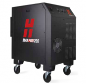
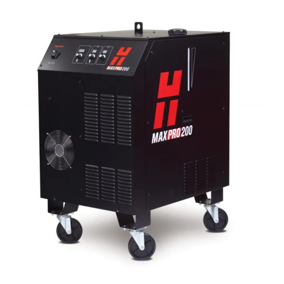
MAXPRO200

Система плазменной резки MAXPRO200, для которой в качестве плазмообразующего газа используется воздух или кислород, характеризуется впечатляющими скоростями, однородным качеством резки и исключительно высоким сроком службы расходных деталей. Оптимизированные параметры резки можно задавать и контролировать одним действием, что упрощает эксплуатацию системы. Система MAXPRO200 обеспечивает надежную производительность в широком диапазоне промышленных применений, поскольку разработана для мощной механизированной и ручной резки и строжки в тяжелом цикле
Максимальная производительность
Система MAXPRO200 максимизирует производительность за счет сочетания высоких скоростей резки и быстрых изменений процессов.

Самые высокие скорости резки в данном классе оборудования позволяют производить больше готовых деталей в час.
100%-ный рабочий цикл для самых жестких производственных условий.
Быстрый переход между резкой, строжкой, механизированной и ручной обработкой благодаря автоматической настройке, проводам, для подсоединения которых не требуются инструменты, и возможности быстрого отключения резаков.
Простая эксплуатация
Самая простая в эксплуатации система воздушно — плазменной и кислородно-плазменной резки в своем классе: простота установки, эксплуатации, достижения максимальной производительности.

Понятный одноэтапный интерфейс и система автоматической регулировки подачи газа обеспечивают стабильные результаты без вмешательства оператора.
Расширенная диагностика упрощает поиск и устранение неисправностей и обслуживание.
Дополнительные каналы последовательной связи позволяют полностью контролировать систему с ЧПУ.
Шаг к самой передовой резке
Сравнение системы MAXPRO200 с системой кислородной резки
Показатели скоростей резки и времени прожига в 7 раз лучше, что позволяет обеспечить максимальную производительность.

Значительно более низкие эксплуатационные затраты на производство деталей из листов толщиной до 50 мм.
Меньшее образование окалины, меньший изгиб и меньший участок, который подвергается нагреву, что позволяет свести к минимуму дорогостоящие операции вторичной обработки.
Повышеная универсальность для резки и строжки низкоуглеродистой стали, нержавеющей стали, алюминия, а также наложенных друг на друга, окрашенных или ржавых листов металла.
Повышенная безопасность резки низкоуглеродистой стали по сравнению с применяемым при кислородной резки ацетиленом, который является легковоспламеняющимся газом.
Низкие эксплуатационные затраты
Исключительно высокий срок службы расходных деталей и стабильная производительность обеспечивают экономичность.
Сделайте больше с меньшими энергозатратами. Запатентованные конструкции расходных деталей обеспечивают самые высокие в данном классе оборудования скорости резки и мощный промышленный прожиг при использовании более низкой силы тока.
Превосходное качество и однородность резки минимизируют дорогостоящие операции вторичной обработки.
Передовые технологии расходных деталей, включая LongLife®, CoolFlow™ и TrueFlow™, существенно повышают срок их службы, что обеспечивает сокращение затрат на производство детали.
Надежная работа
Система сконструирована и протестирована с использованием проверенного процесса разработки, который применялся для семейства продуктов HyPerformance® HPRXD®. Это позволяет обеспечить превосходную надежность в самых требовательных средах резки.
В процессе разработки системы Hypertherm проходят суровые испытания на надежность, которые эквивалентны годам эксплуатации в экстремальных условиях.
Количество внутренних деталей MAXPRO200 в два раза меньше по сравнению с другими системами на рынке. Это означает более высокую надежность и удобство обслуживания.
Самодиагностика производится автоматически при запуске и постоянно в процессе резки.

Компания Hypertherm (США) специализируется на проектировании и производстве аппаратов плазменной резки, которые используются в различных областях, начиная от ремонта автомобилей и заканчивая машиностроением и судостроением.
Узнайте больше на странице компании
Параметры подключения
| Давление воздуха | 6.2 бар |
| Используемые газы | Сжатый воздух, кислород, азот |
| Электропитание | 3х200-600/50-60 В/Гц |
| Потребляемая мощность | 33 кВт |
Габариты
Модельный ряд
Особенности
HYPERTHERM MAXPRO 200 (арт. 078614) — это мощнейшая система плазменной резки для промышленного применения с впечатляющей скоростью резки, использующая в качестве газа чистый воздух, кислород или азот;
100%-й рабочий цикл при использовании плазменной резки для самых сложных задач;
Исключительно большой срок службы расходных материалов благодаря запатентованным технологиям HYPERTHERM, включая LongLife, CoolFlow™ и TrueFlow™;
Легкость подключения и эксплуатации, автоматическая система регулировки подачи газа;
При запуске система производит самодиагностику для выявления возможных неисправностей.
Рекомендации по применению
У нас Вы также можете купить компрессоры, осушители и фильтры для подготовки воздуха.
Линейка моделей плазморезов для обработки листового металла на средних и крупных предприятиях для промышленного производства изделий из листового проката стали и цветных металлов.
Резаки
К источнику Hypertherm необходимо приобрести ручные резаки. У нас в наличии резаки для резки и строжки с углами установки сопла 90º и 65º.
Источники:
https://knuth-industry. ru/articles/%D1%80%D0%B0%D1%81%D0%BA%D1%80%D0%BE%D0%B9-%D0%BC%D0%B5%D1%82%D0%B0%D0%BB%D0%BB%D0%B0-%D1%81%D1%82%D0%B0%D1%82%D1%8C%D0%B8/maxpro200/
https://mossklad. ru/_PRODUCTPAGE/369409
Добрый день, коллеги.
Вводные такие: 2 года станку и источнику. изрезали уже 100500 тонн различного металла и в частности нержавейки. все настройки (напряжение дуги, высота пробоя и реза, скорость и прочее) прописаны в станке и не меняли те самые 2 года, плюс станок подхватывает скорость из кода УП. Тоесть, в целом с этим все стабильно.
Вчера достали обрезки нержавейки 4мм, которые остались после резки на этом станке, решили вырезать детали и тут началось странное:
металл кое-как пробивается и потом не прорезается во время передвижения резака. скорость установлена 2300 мммин (и еще раз — до этого на такой скорости все резалось без проблем). в ручном режиме перемещения удалось подобрать скорость, на которой прорезается металл — 1500 мммин, но при этом рез очень страннный… вырезая прямоугольник получаем на одной из сторон нормальный рез, одна все равно продувается плохо, на третьей и четвертой рез под углом (на вид примерно 45 гр, как будто фаску снимали)… расходники оригинал гипертерм, поставили новые прям перед началом резки. в этот же день ранее резали на 130А чернуху 10мм — все режется отлично…
совершенно непонятно, в чем может быть причина, т.к. сталкиваюсь с такой проблемой впервые…
надеюсь на ваши советы и помощь.
-
xfour
- Новичок
- Сообщения: 9
- Зарегистрирован: 11 апр 2019, 12:02
- Репутация: 0
- Контактная информация:
Hypertherm max pro 200
Описание станка, основные характеристики:
Рабочее поле:
Обрабатываемые материалы: сталь3 20мм
Чертежи, фото, видео станка:—
Примеры изделий (фото):
Вопросы: Господа нуждаюсь в Вашей помощи, возникла проблема с отверстиями (фото прилагаю верх/низ) источник Hypertherm max pro200,стойка SH-2012 AH1, софт cncKad v12.1.455.
Что пробовал: пробовал разные токи, разные расходники, скоростные режимы, высоту пробивки, высоту зазора при резке, при создании расскроя деталей, на отверстия вход 5мм выход 3мм, перекрытие 2мм, отверстия режутся против часовой стрелки, контур по часовой.
Что плучилось:результат на фото
Что не получилось: около равносторонее отверстия.
Ориентировочный бюджет: -.
- Вложения
-
-
-
X-Ray
- Мастер
- Сообщения: 596
- Зарегистрирован: 04 фев 2016, 23:06
- Репутация: 275
- Настоящее имя: Дамир
- Контактная информация:
Re: Hypertherm max pro 200
Сообщение
X-Ray » 11 апр 2019, 13:21
Начало должно находится за пределами рабочей траектории. В данном случае в глубине отверстия.

- Безымянный.png (6.69 КБ) 6330 просмотров
Программа GGEasy (фрезеровка из гербера, производство ПП на ЧПУ) GERBER_X3/releases
Прежде чем писать о багах проверьте, является ли ваша версия последней!
Баги — глюки и ПРЕДЛОЖЕНИЯ(Хотелки) писать СЮДА!!! Багтрекер
Тестовая версия
-
xfour
- Новичок
- Сообщения: 9
- Зарегистрирован: 11 апр 2019, 12:02
- Репутация: 0
- Контактная информация:
Re: Hypertherm max pro 200
Сообщение
xfour » 11 апр 2019, 13:40
X-Ray писал(а):Начало должно находится за пределами рабочей траектории. В данном случае в глубине отверстия.
Безымянный.png
Спасибо за ответ, но у меня начало и конец за пределами рабочей траектории, вход под углом 90°, выход под 45°
-
xfour
- Новичок
- Сообщения: 9
- Зарегистрирован: 11 апр 2019, 12:02
- Репутация: 0
- Контактная информация:
Re: Hypertherm max pro 200
Сообщение
xfour » 11 апр 2019, 13:58
Вход и выход пробовал делать под разными углами и разной длинной. визуально кажется что плазматрон идёт на второй круг по этому и получается не аккуратное яйцо, то есть мне кажен что дуга гаснет позже чем надо, как это поправить честно говоря не знаю…
-
X-Ray
- Мастер
- Сообщения: 596
- Зарегистрирован: 04 фев 2016, 23:06
- Репутация: 275
- Настоящее имя: Дамир
- Контактная информация:
Re: Hypertherm max pro 200
Сообщение
X-Ray » 11 апр 2019, 17:11
xfour писал(а):вход под углом 90°
Может из-за того что вход под 90° то ЧПУ сначала тормозит до угла, а потом набирает скорость, и этого времени оказывается достаточно для сдувания лишнего материала. Обратите внимание на скорость перемещения головы.
Программа GGEasy (фрезеровка из гербера, производство ПП на ЧПУ) GERBER_X3/releases
Прежде чем писать о багах проверьте, является ли ваша версия последней!
Баги — глюки и ПРЕДЛОЖЕНИЯ(Хотелки) писать СЮДА!!! Багтрекер
Тестовая версия
-
xfour
- Новичок
- Сообщения: 9
- Зарегистрирован: 11 апр 2019, 12:02
- Репутация: 0
- Контактная информация:
Re: Hypertherm max pro 200
Сообщение
xfour » 11 апр 2019, 17:28
X-Ray писал(а):
xfour писал(а):вход под углом 90°
Может из-за того что вход под 90° то ЧПУ сначала тормозит до угла, а потом набирает скорость, и этого времени оказывается достаточно для сдувания лишнего материала. Обратите внимание на скорость перемещения головы.
Старт при пробивке на низкой скорости, далее скорость одинаковая, так как заход по радиусу не прямой, то вход и само отверстие режется на одной скорости…
-
xfour
- Новичок
- Сообщения: 9
- Зарегистрирован: 11 апр 2019, 12:02
- Репутация: 0
- Контактная информация:
Re: Hypertherm max pro 200
Сообщение
xfour » 12 апр 2019, 00:30
Видел это видео давно, весь процесс отстроил по мануала/советам hypertherm, но как дуболомам в креслах объяснить, что есть допуски, и так станок выше допусков качество даёт, а они всё не уймутся, я вот думаю может попробовать расскрой делать через другую прогу, только вот не знаю поможет ли…
-

Мастерю
- Мастер
- Сообщения: 520
- Зарегистрирован: 17 фев 2019, 13:45
- Репутация: 34
- Настоящее имя: Сергей
- Контактная информация:

Re: Hypertherm max pro 200
Сообщение
Мастерю » 12 апр 2019, 00:43
xfour писал(а):Вход и выход пробовал делать под разными углами и разной длинной. визуально кажется что плазматрон идёт на второй круг по этому и получается не аккуратное яйцо, то есть мне кажен что дуга гаснет позже чем надо, как это поправить честно говоря не знаю…
А не пробовали вход и выход под наиболее малыми углами. И, что, еще — момент начала выхода попробовать чуть сместить.
Потренероваться есть на чем? Попробуйте сначала сделать вход, но сделав некоторую дугу сделать выход и затем посмотреть места входа и выхода на окружность, так, на мой взгляд, будет проще понять в какой момент времени (на входе или на выходе) образуется этот «проплав». Имхо…
-
xfour
- Новичок
- Сообщения: 9
- Зарегистрирован: 11 апр 2019, 12:02
- Репутация: 0
- Контактная информация:
Re: Hypertherm max pro 200
Сообщение
xfour » 03 май 2019, 14:11
Мастерю писал(а):
xfour писал(а):Вход и выход пробовал делать под разными углами и разной длинной. визуально кажется что плазматрон идёт на второй круг по этому и получается не аккуратное яйцо, то есть мне кажен что дуга гаснет позже чем надо, как это поправить честно говоря не знаю…
А не пробовали вход и выход под наиболее малыми углами. И, что, еще — момент начала выхода попробовать чуть сместить.
Потренероваться есть на чем? Попробуйте сначала сделать вход, но сделав некоторую дугу сделать выход и затем посмотреть места входа и выхода на окружность, так, на мой взгляд, будет проще понять в какой момент времени (на входе или на выходе) образуется этот «проплав». Имхо…
С проплавом кое как совладал, теперь новые приколы отверстия с обратной стороны просто ужас, конусность хуже наверное не бывает, короче потоптался на месте, железа покрошил не мало, толку только… Закрадываются мысли перейти с cnckad’a на другой софт хотя бы что бы задавать обработку по иному, соседи пользуются древним saps, источник тоже hypertherm только 130, у них всё норм с отверстиями до толщины 20мм…
-

magnetic
- Мастер
- Сообщения: 429
- Зарегистрирован: 03 авг 2015, 11:27
- Репутация: 73
- Настоящее имя: Алексей
- Контактная информация:

Re: Hypertherm max pro 200
Сообщение
magnetic » 03 май 2019, 14:47
отверстия нормальные для плазмы
намечать плазмой и потом сверлить, если нужны нормальные отверстия.
Хипертерм еще технологию трухол рекомендует, но ценик возможно вам не понравится.
попробуйте sheetcam
Вилки и ложки на фото из AISI304!
-
Dave
- Новичок
- Сообщения: 6
- Зарегистрирован: 17 ноя 2019, 22:58
- Репутация: 0
- Контактная информация:
Re: Hypertherm max pro 200
Сообщение
Dave » 18 ноя 2019, 23:35
Трухол с автоматической консолью работает плюс софт не всякий плюс чпу. С макспро не работает.
-
JAN_14
- Новичок
- Сообщения: 6
- Зарегистрирован: 19 апр 2019, 13:45
- Репутация: 0
- Настоящее имя: Ернар
- Контактная информация:
Re: Hypertherm max pro 200
Сообщение
JAN_14 » 27 фев 2020, 18:29
Можете, помощь плазму под cnckad настроиь? Плазма Китай. Стойка sf-2300s-qg. Источник, Hyperterm 125A. Хочу сравнить. Шя под pronest настроил, работает. Родная проги Starcam аналог китайский от Fastcam. Оба есть ключи в месте станком. Pronest лучше и легче
-
Evokasi
- Новичок
- Сообщения: 2
- Зарегистрирован: 13 фев 2019, 17:45
- Репутация: 0
- Настоящее имя: Евгений
- Контактная информация:
Re: Hypertherm max pro 200
Сообщение
Evokasi » 07 апр 2021, 19:54
Очень похоже на увеличенный зазор в механике по одной из осей. Что бы это понять, надо перед резкой нанести координаты осей на деталь, тем самым показав как она располагается в режущем столе.
- Лазерная резка
- Машины плазменной резки
- Источники для резки с ЧПУ
- Расходные материалы
- Программное обеспечение
Инструкция по эксплуатации системы MAXPro200 от Hypertherm содержит всю необходимую информацию для эффективной и безопасной работы с данным оборудованием, включая сведения об установке, электромагнитной совместимости, гарантийных обязательствах производителя и техническом обслуживании.
![]() MAXPro200 инструкция по эксплуатации
MAXPro200 инструкция по эксплуатации
Популярные товары
-
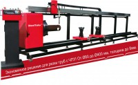
Станок для резки труб с ЧПУ TubeTailor II
Машины для резки труб -
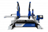
MAXPRO200
Установки для ручной резки -
Машина плазменной резки Jantar
Машины плазменной резки -
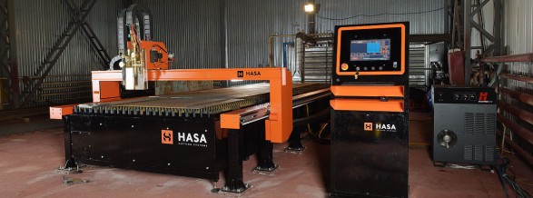
Плазменная машина термической резки HASA
Машины плазменной резки -
Powermax 125
Установки для ручной резки -
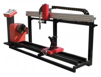
Установка термической резки труб Steel Tailor Tube I
Машины для резки труб -
Steel Tailor Power
Портативные системы -
Uppercut
Установки для ручной резки -
Galaxy SQL4
Машины плазменной резки -
Swift-CUT — портативная 3-х координатная система резки с ЧПУ
Машины плазменной резки -
Машина плазменной резки Sapphire
Машины плазменной резки -
Powermax105 SYNC
Установки для ручной резки -
Powermax 105
Установки для ручной резки -
Legacy XP
Портативные системы


<
>
Наши преимущества
![]()
![]()
Шоу-рум
Представлено оборудование в различных ценовых сегментах и с разными конструктивными
особенностями
![]()
Тест-драйв
Возможность познакомиться с технологией резки, собственноручно протестировав
интересующую Вас модель оборудования
![]()
![]()
Гарантия качества
Мы поставляем только качественный, оригинальный и сертифицированный товар
![]()
Лизинговые программы
Позволят привлечь внешнее финансировать и получить значительные финансовые льготы для
Вашего предприятия
![]()
Монтаж оборудования
Монтаж станков и ввод их в эксплуатацию — гарантия бесперебойной работы
оборудования
![]()
Надежный сервис
Авторизованный сервисный персонал компании обеспечит оперативный отклик на Ваше
обращение
![]()
- Manuals
- Brands
- Hypertherm Manuals
- Welding System
- MAXPRO200
- Instruction manual
-
Contents
-
Table of Contents
-
Bookmarks
Quick Links
MAXPRO200
®
Instruction Manual
807700 – Revision 1
Related Manuals for Hypertherm MAXPRO200
Summary of Contents for Hypertherm MAXPRO200
-
Page 1
MAXPRO200 ® Instruction Manual 807700 – Revision 1… -
Page 2
Purchase date: _______________________________________________________________ Distributor: __________________________________________________________________ ____________________________________________________________________________ ____________________________________________________________________________ Maintenance notes: ____________________________________________________________________________ ____________________________________________________________________________ ____________________________________________________________________________ ____________________________________________________________________________ ____________________________________________________________________________ ____________________________________________________________________________ MXAXPRO200, Sensor THC, Sensor PHC, and Hypertherm are trademarks of Hypertherm, Inc. and may be registered in the United States and other countries. © 2013 Hypertherm, Inc. -
Page 3
MAXPRO200 Instruction Manual 807700 – Revision 1 English March 2013 Hypertherm, Inc. Hanover, NH 03755 USA… -
Page 4
55 11 2409 2636 Tel Hypertherm (S) Pte Ltd. 55 11 2408 0462 Fax 82 Genting Lane Media Centre Hypertherm México, S.A. de C.V. Annexe Block #A01-01 Avenida Toluca No. 444, Anexo 1, Singapore 349567, Republic of Singapore Colonia Olivar de los Padres 65 6841 2489 Tel Delegación Álvaro Obregón… -
Page 5: Table Of Contents
Additional safety information …………………………..20 Warning labels ………………………………20 Electromagnetic Compatibility (EMC) …………………23 Introduction ………………………………..23 Installation and use ……………………………… 23 Assessment of area …………………………….. 23 Methods of reducing emissions …………………………23 Mains supply ………………………………23 MAXPRO200 Instruction Manual 807700 Revision 1…
-
Page 6
The REACH regulation …………………………….32 Proper handling and safe use of chemicals ……………………..32 Fumes emission and air quality ………………………….32 Specifications ……………………….33 System description ………………………………33 General ………………………………..33 Power supply ………………………………33 Ignition console ……………………………..33 Torch ………………………………..33 Gas system ………………………………33 MAXPRO200 Instruction Manual 807700 Revision 1… -
Page 7
Premixed coolant for standard operating temperatures ………………..63 Custom Coolant mix for cold operating temperatures (below -12° C / 10° F) …………64 Custom Coolant mix for hot operating temperatures (above 38° C / 100° F) …………65 Water purity requirements …………………………. 65 MAXPRO200 Instruction Manual 807700 Revision 1… -
Page 8
Gouge profiles and metal removal rates ……………………..85 Varying the gouge profile …………………………..86 Cutting parameters ………………………………86 Mechanized consumables …………………………..86 Hand held torch consumables …………………………..86 Hand held cutting and gouging consumable selection …………………87 Mild steel ………………………………87 Stainless steel …………………………….88 MAXPRO200 Instruction Manual 807700 Revision 1… -
Page 9
Preventive maintenance ……………………………119 Power supply status …………………………….120 Sequence of operation and power supply status ……………………121 PCB block diagram …………………………….126 Error codes …………………………………127 Diagnostic functions …………………………….128 Troubleshooting table …………………………….129 Initial checks ……………………………….137 Power measurement …………………………….138 MAXPRO200 Instruction Manual 807700 Revision 1… -
Page 10
Weekly: ……………………………….. 159 Semi-annually: …………………………….159 Annually: ………………………………159 Preventive Maintenance Protocol Checklist ……………………..160 Year 1 preventive maintenance (PM) kits ……………………..161 Maintenance kits parts list …………………………161 Service parts replacement schedule ……………………….161 MAXPRO200 Instruction Manual 807700 Revision 1… -
Page 11
Mechanized torch consumable kit – 428013 ……………………178 Hand torch consumable kit – 428014 ……………………..179 Supply gas hoses ………………………………180 Oxygen …………………………………180 Nitrogen ……………………………….180 Air ………………………………….180 Recommended spare parts …………………………..181 Wiring Diagrams ……………………..183 Wiring diagram symbols …………………………..184 MAXPRO200 Instruction Manual 807700 Revision 1… -
Page 12
11 — Toxicological information …………………………201 12 — Ecological information …………………………..201 13 — Disposal considerations ………………………….. 201 14 — Transport information …………………………..202 15 — Ecological information …………………………..202 16 — Other information …………………………….202 MAXPRO200 Instruction Manual 807700 Revision 1… -
Page 13: Safety
• Wait 5 minutes after removal of power before entering • Always follow these instructions for disconnecting the enclosure to allow stored energy to discharge. power before inspecting or changing torch consumable parts. MAXPRO200 Instruction Manual 807700 Revision 1…
-
Page 14: Electric Shock Can Kill
• Provide a disconnect switch close to the power supply grounding conductor first. with properly sized fuses. This switch allows the • Each Hypertherm plasma system is designed to be operator to turn off the power supply quickly in an used only with specific Hypertherm torches. Do not emergency situation.
-
Page 15: Cutting Can Cause Fire Or Explosion
• Do not cut under water with fuel gases containing hydrogen. • Cutting under water with fuel gases containing hydrogen can result in an explosive condition that can detonate during plasma cutting operations. MAXPRO200 Instruction Manual 807700 Revision 1…
-
Page 16: Toxic Fumes Can Cause Injury Or Death
Empty and properly clean the container first. • Monitor or test the air quality at the site as needed. • Consult with a local expert to implement a site plan to ensure safe air quality. MAXPRO200 Instruction Manual 807700 Revision 1…
-
Page 17: Grounding Safety
• Tighten all electrical connections to avoid excessive heating. STATIC ELECTRICITY CAN DAMAGE CIRCUIT BOARDS Use proper precautions when handling printed circuit boards: • Store PC boards in anti-static containers. • Wear a grounded wrist strap when handling PC boards. MAXPRO200 Instruction Manual 807700 Revision 1…
-
Page 18: Compressed Gas Equipment Safety
• Keep away from the torch tip. Plasma arc comes on immediately when the torch switch is activated. • Do not hold metal near the cutting path. • Never point the torch toward yourself or others. MAXPRO200 Instruction Manual 807700 Revision 1…
-
Page 19: Arc Rays Can Burn Eyes And Skin
41 to 60 A 61 to 80 A 81 to 125 A 126 to 150 A 151 to 175 A 176 to 250 A 251 to 300 A 301 to 400 A 401 to 800 A MAXPRO200 Instruction Manual 807700 Revision 1…
-
Page 20: Pacemaker And Hearing Aid Operation
A PLASMA ARC CAN DAMAGE FROZEN PIPES Frozen pipes may be damaged or can burst if you attempt to thaw them with a plasma torch. MAXPRO200 Instruction Manual 807700 Revision 1…
-
Page 21: Dry Dust Collection Information
Note 2 – Users of Hypertherm manuals should consult and comply with all applicable federal, state, and local Consult your local “Authority Having Jurisdiction” (AHJ) laws and regulations.
-
Page 22: Laser Radiation
Exposure to the laser output can result in serious eye injury. Avoid direct eye exposure. For your convenience and safety, on Hypertherm products that use a laser, one of the following laser radiation labels has been applied on the product near where the laser beam exits the enclosure. The maximum output (mV), wavelength emitted (nM) and, if appropriate, the pulse duration is also provided.
-
Page 23: Symbols And Marks
SYMBOLS AND MARKS Your Hypertherm product may have one or more of the following markings on or near the data plate. Due to differences and conflicts in national regulations, not all marks are applied to every version of a product.
-
Page 24: Additional Safety Information
7. Ne pas enlever, détruire ni couvrir cette étiquette. Replace if it is missing, damaged, or worn (PN 110584 Rev C). La remplacer si elle est absente, endommagée ou usée (PN 110584 Rev C). MAXPRO200 Instruction Manual 807700 Revision 1…
-
Page 25
Become trained. Only qualified personnel should operate this equipment. Use torches specified in the manual. Keep non-qualified personnel and children away. Do not remove, destroy, or cover this label. Replace if it is missing, damaged, or worn. MAXPRO200 Instruction Manual 807700 Revision 1… -
Page 26
Safety MAXPRO200 Instruction Manual 807700 Revision 1… -
Page 27: Electromagnetic Compatibility (Emc)
Introduction Other supply cables, control cables, signaling and telephone cables; above, below and adjacent to the Hypertherm’s CE-marked equipment is built in compliance cutting equipment. with standard EN60974-10. The equipment should be installed and used in accordance with the information b.
-
Page 28: Maintenance Of Cutting Equipment
(nozzle for laser heads) at the same time. The operator should be insulated from all such bonded metallic components. Instruction Manual 807700 Revision 1 MAXPRO200…
-
Page 29: Warranty
Products or as to the results which Hypertherm is notified of a defect (i) with respect to the may be obtained therefrom, and all implied warranties or…
-
Page 30: Patent Indemnity
Hypertherm not in strict conformity with Hypertherm’s appropriate to defend and to hold Hypertherm harmless in specifications and in cases of designs, processes, the event of any cause of action arising from the use of the formulae, or combinations not developed or purported to products.
-
Page 31: Product Stewardship
Countries that require CE marking or have compulsory Once the product has left the Hypertherm factory, the EMC regulations must use CE versions of Hypertherm certification test marks are invalidated if any of the products with the CE marking on the data plate.
-
Page 32: Safe Installation And Use Of Shape Cutting Equipment
International Electrotechnical performing these tests, may be much greater than the standards, and shall not rely on Hypertherm in any respect benefit of periodic inspection and testing. regarding the interpretation or application of such standards.
-
Page 33: Higher-Level Systems
Higher-level systems When a system integrator adds additional equipment; such as cutting tables, motor drives, motion controllers or robots; to a Hypertherm plasma cutting system, the combined system may be considered a higher-level system. A higher-level system with hazardous moving…
-
Page 34
Product Stewardship MAXPRO200 Instruction Manual 807700 Revision 1… -
Page 35: Environmental Stewardship
The Hypertherm Environmental Specification requires used in CSA versions of Powermax and other products RoHS, WEEE and REACH substance information to be manufactured by Hypertherm that are either out of scope provided by Hypertherm’s suppliers. or exempt from RoHS are continuously being converted to RoHS compliance in anticipation of future requirements.
-
Page 36: The Reach Regulation
23 metals are listed in ASTM D 4185. An industrial Hypertherm in, on, for, or with its shape cutting equipment hygienist should be used to determine the optimum are used in very small quantities (except the coolant) and…
-
Page 37: Specifications
Specifications System description General The MAXPRO200 plasma system is designed to cut a wide range of thicknesses of mild steel, stainless steel, and aluminum. Power supply The power supply is a 200 A, 165 VDC constant-current supply. It contains the circuitry to ignite a torch, plus a heat exchanger and a pump to cool the chopper and torch.
-
Page 38
Specifications MAXPRO200 Instruction Manual 807700 Revision 1… -
Page 39: Cooling System
Shield gas Plasma gas Shield gas Plasma gas Shield gas Amperage Cutting 50 A Air or O Cutting 130 A Air or O Cutting 130 A Cutting 200 A Air or O Cutting 200 A MAXPRO200 Instruction Manual 807700 Revision 1…
-
Page 40: Power Supply
078615 CE/GOST-R 37.4 078616 50-60 37.4 078609 37.4 078617 37.4 63.5 mm (2.5 inches) 688 mm (27.1 inches) 133 mm (5.25 inches) 998 mm (39.3 inches) 927 mm (40.1 inches) 335.7 kg (740 lb) MAXPRO200 Instruction Manual 807700 Revision 1…
-
Page 41: Mechanized Torches
The minimum bend radius for the torch lead is 152.4 mm (6.0 inches) 1.02 kg (2.25 lb) 397.15 mm (15.64 inches) 279.40 mm (11.00 inches) 117.75 mm (4.64 inches) 12.70 mm (0.50 inches) 44.20 mm (1.74 inches) 46 degrees 44.20 mm (1.74 inches) MAXPRO200 Instruction Manual 807700 Revision 1…
-
Page 42: Quick-Disconnect Torch — 428027 Or 428028
435.33 mm (17.14 inches) 279.40 mm (11.00 inches) 76.98 mm (3.03 inches) 78.95 mm (3.11 inches) 12.70 mm (0.50 inches) 44.20 mm (1.74 inches) 46 degrees 57.15 mm (2.25 inches) 44.20 mm (1.74 inches) MAXPRO200 Instruction Manual 807700 Revision 1…
-
Page 43: Hand Torches
The minimum bend radius for the torch lead is 152.4 mm (6.0 inches) 0.91 kg (2.0 lb) 310.40 mm (12.22 inches) 90 degrees 44.20 mm (1.74 inches) 305.05 mm (12.01 inches) 149.10 mm (5.87 inches) MAXPRO200 Instruction Manual 807700 Revision 1…
-
Page 44: Degree Hand Torch — 420107
The minimum bend radius for the torch lead is 152.4 mm (6.0 inches) 0.91 kg (2.0 lb) 290.58 mm (11.44 inches) 65 degrees 44.20 mm (1.74 inches) 285.24 mm (11.23 inches) 238.51 mm (9.39 inches) MAXPRO200 Instruction Manual 807700 Revision 1…
-
Page 45: Installation
Claims for damage during shipment – If your unit was damaged during shipment, you must file a claim with the carrier. Hypertherm will furnish you with a copy of the bill of lading upon request. If you need additional assistance, call customer service listed in the front of this manual, or your authorized Hypertherm distributor.
-
Page 46: Placement Of System Components
To prevent leaks in the system, tighten all gas connections as shown below. Torque specifications Gas or water hose size kgf-cm lbf-in lbf-ft Up to 10 mm (3/8 in) 8.9–9.8 75–85 6.25–7 12 mm (1/2 in) 41.5–55 360–480 30–40 MAXPRO200 Instruction Manual 807700 Revision 1…
-
Page 47: Supply Gas Hoses
Installation System components Power supply Torch Cable and lead Torch lead Work lead CNC interface cable Supply gas hoses Customer supplied power cable Main power cable MAXPRO200 Instruction Manual 807700 Revision 1…
-
Page 48: Recommended Grounding And Shielding Practices
Note: The grounding practices in this section have been used on many installations with excellent results, and Hypertherm recommends that these practices be a routine part of the installation process. The actual methods used to implement these practices may vary from system to system, but should remain as consistent as possible.
-
Page 49
9. Each Hypertherm component, as well as any other CNC or motor drive cabinet or enclosure, must have a separate ground cable to the common (star) ground on the table. This includes the ignition console, whether if it is bolted to the plasma system or to the cutting table. -
Page 50
Cable to the cutting table ground bus Ground cables from components on the gantry The following diagram shows an example of grounding the components in a plasma cutting system. MAXPRO200 Instruction Manual 807700 Revision 1… -
Page 51
CNC chassis Table ground bus bar Torch height control module (ArcGlide, CommandTHC) Gantry ground bus bar System-specific component such as a cooler or chiller Torch height control lifter (ArcGlide, Sensor THC, Sensor PHC, or other) MAXPRO200 Instruction Manual 807700 Revision 1… -
Page 52: Placement Of The Power Supply
Do not place any filter device over the air intake locations, which reduces cooling efficiency and VOIDS THE WARRANTY. • Do not place the power supply on an incline greater than 10° to prevent it from toppling. MAXPRO200 Instruction Manual 807700 Revision 1…
-
Page 53: Torch Lead Connections
2. Connect the CPC connector to the CPC receptacle. MAXPRO200 Instruction Manual 807700 Revision 1…
-
Page 54
To disconnect a fitting, push the connector-collar and hose toward the fitting, hold the collar in place and pull the hose away from the fitting. 3. Connect the coolant return hose (red). 4. Connect the plasma gas hose (black). MAXPRO200 Instruction Manual 807700 Revision 1… -
Page 55
5. Connect the pilot arc/shield gas hose (blue). 6. Connect the negative lead/coolant supply hose (blue with green tape). MAXPRO200 Instruction Manual 807700 Revision 1… -
Page 56: Work Lead Connections
23 m (75 feet) 223338 30 m (100 feet) Remove the first nut and washer from the work lead terminal and use it to secure the work lead to the terminal. Lower frame of work table (typical) MAXPRO200 Instruction Manual 807700 Revision 1…
-
Page 57: Torch Connections
Note: The connections between the straight torch main body and the torch leads are identical to the connections between the quick-disconnect receptacle and the torch leads. Align the quick disconnect receptacle, or the straight torch main body, to the torch leads and secure using the push-to-connect fittings. Connect to torch lead MAXPRO200 Instruction Manual 807700 Revision 1…
-
Page 58: Connect The Torch To The Quick-Disconnect Receptacle
The o-rings should look shiny, but there should not be any excess or built-up lubricant. Be certain that there is no space between the torch body and the o-ring on the quick-disconnect. MAXPRO200 Instruction Manual 807700 Revision 1…
-
Page 59: Torch Mounting And Alignment
Note: The bracket should be as low on the torch sleeve as possible to minimize vibration at the tip of the torch. Torch alignment To align the torch at right angles to the workpiece, use a square as shown above. MAXPRO200 Instruction Manual 807700 Revision 1…
-
Page 60: Cnc Interface Cable
J6 on the control board. Open the clips by depressing the release tab, and add the CNC cable to the wires that are already present in the clip. See the figure on the next page. MAXPRO200 Instruction Manual 807700 Revision 1…
-
Page 61
Installation CNC cable routing and connection to control board from the To J6 on the control board MAXPRO200 Instruction Manual 807700 Revision 1… -
Page 62: Remote On/Off Switch (Provided By Customer)
2. Remove the jumper wire between terminal 1 and terminal 2. Use a sturdy tool to depress the corresponding orange release buttons on the spring clamp connector 1 2 3 4 5 6 7 MAXPRO200 Instruction Manual 807700 Revision 1…
-
Page 63
Note: The power switch on the power supply must be in the ON position for the remote switch to function and the remote switch must be in the ON position (closed) for the power switch on the power supply to function. MAXPRO200 Instruction Manual 807700 Revision 1… -
Page 64: Power Requirements
(4 AWG) 13.3 mm (6 AWG) 600 VAC 36 amps 50 amps 13.3 mm (6 AWG) 8.3 mm (8 AWG) Note: Wire AWG recommendations came from Table 310-16 of the National Electric Code Handbook (USA). MAXPRO200 Instruction Manual 807700 Revision 1…
-
Page 65: Line Disconnect Switch
Wire sizes vary based on the temperature rating of the cable insulation and the distance of the unit from the main box. Use a 4-conductor Type SO input power cable with a conductor temperature rating of 60° C (140° F) or 90° C (194° F). Installation must be performed by a licensed electrician. MAXPRO200 Instruction Manual 807700 Revision 1…
-
Page 66: Connect The Power
North American wire colors European wire colors U = Black U = Black V = White V = Blue W = Red W = Brown (PE) Earth ground = Green/yellow (PE) Earth ground = Green/yellow Ground MAXPRO200 Instruction Manual 807700 Revision 1…
-
Page 67: Torch Coolant Requirements
Premixed coolant for standard operating temperatures Use Hypertherm premixed coolant (028872) when operating in a temperature range of -12° C to 40° C (10° F to 104° F). Refer to the custom coolant mix recommendations, if temperatures during operation are ever outside of this range.
-
Page 68: Custom Coolant Mix For Cold Operating Temperatures (Below -12° C / 10° F)
Mix 100% propylene glycol (028873) with the premixed Hypertherm coolant (028872) to increase the percentage of glycol in the premixed Hypertherm coolant. The 100% glycol solution can also be mixed with purified water (see the chart below for water purity requirements) to achieve the required protection from freezing.
-
Page 69: Custom Coolant Mix For Hot Operating Temperatures (Above 38° C / 100° F)
μS/cm mΩ-cm (ppm of NaCl) (gpg of CaCO2) at 25° C (77° F) at 25° C (77° F) Pure water (for reference 0.055 18.3 only) Maximum purity 0.206 0.010 Minimum purity 0.054 0.43 Maximum potable water 1000 0.001 (for reference only) MAXPRO200 Instruction Manual 807700 Revision 1…
-
Page 70: Fill The Power Supply With Coolant
4. Add coolant to the power supply until the tank is system and add coolant to the tank until it is full again. full and replace the filler cap. Repeat steps 2 and 3 until no error is displayed. MAXPRO200 Instruction Manual 807700 Revision 1…
-
Page 71: Connect The Supply Gases
2. Remove the Air fitting 015012 (1/4 inch NPT X #6 MALE) from the filter/regulator. Install an 015103 adaptor to use the nitrogen supply gas hose offered by Hypertherm. b. Use the 1/4 inch NPT Female port from which the air fitting was removed to connect a user supplied N supply gas hose.
-
Page 72
4. Connect only filtered and regulated oxygen to the plasma gas Inlet. See Gas regulators on page 72 for a suitable oxygen regulator. Note: An oxygen fitting kit (428054) with the parts described below is available from Hypertherm. There are several options for connecting the oxygen supply gas line: Remove the 015811 fitting and put on an 015009 fitting (user must order the part. -
Page 73
8 mm (5/16 inch) tubing that you removed from the plasma gas Inlet. Remove the plasma gas tubing and 8 mm (5/16 inch) fitting (015811) and connect to the 1/4 inch NPT female threads. 015811 MAXPRO200 Instruction Manual 807700 Revision 1… -
Page 74
Remove the bushing and fitting to connect to 1/4 inch “G” female threads. 015810 051811 5. Reconnect the air supply. 6. Set the gas pressure regulators. See Setting the supply gas regulators on page 71. MAXPRO200 Instruction Manual 807700 Revision 1… -
Page 75: Gas Requirements
005, “Flow gas at full pressure”. Set all supply regulators to a system inlet pressure of 6.2 bar (90 psi). 4. Press and release the current selection knob until the amps icon is illuminated. MAXPRO200 Instruction Manual 807700 Revision 1…
-
Page 76: Gas Regulators
Use a high-quality, 2-stage, gas regulator to maintain consistent gas supply pressure from high pressure gas cylinders. The high-quality gas regulators listed below are available from Hypertherm and meet U.S. Compressed Gas Association (CGA) specifications. In other countries, select gas regulators that conform to national or local codes.
-
Page 77: Supply Gas Plumbing
CUTTING WITH OXYGEN CAN CAUSE FIRE OR EXPLOSION Cutting with oxygen as the plasma gas can cause a potential fire hazard due to the oxygen-enriched atmosphere that it creates. As a precaution, Hypertherm recommends that an exhaust ventilation system be installed when cutting with oxygen.
-
Page 78: Supply Gas Hoses
7.5 m (25 ft) 024120 45 m (150 ft) 024211 10 m (35 ft) 024124 60 m (200 ft) 024112 15 m (50 ft) 024764 75 m (250 ft) 024763 20 m (65 ft) MAXPRO200 Instruction Manual 807700 Revision 1…
-
Page 79: Operation
3. Replace consumable parts. See Install and inspect consumables on page 90 for details. 4. Make sure that the torch is perpendicular to the workpiece. Shield Swirl ring Nozzle retaining cap Electrode Nozzle Torch main body (quick-disconnect torch shown) MAXPRO200 Instruction Manual 807700 Revision 1…
-
Page 80: Controls And Indicators
Operation Controls and indicators Control panel descriptions Power switch 3-digit display area Current selection knob 2-digit plasma display area Plasma gas knob 2-digit shield display area Shield gas knob MAXPRO200 Instruction Manual 807700 Revision 1…
-
Page 81: Power Supply Operation
The displays show the set values when idle. • A blinking red dot appears in the bottom right corner of each display when the parameters have been changed from the default setting. MAXPRO200 Instruction Manual 807700 Revision 1…
-
Page 82: 3-Digit Display Functions
This white lamp illuminates when the plasma start signal is given and 6 Plasma start lamp stays illuminated until the start signal is removed. 7 Arc transfer lamp This green lamp illuminates when the arc transfers to the workpiece. MAXPRO200 Instruction Manual 807700 Revision 1…
-
Page 83: Choosing A Cutting Process
You can return to the default setting by pressing and releasing the knob until you return to the original gas selection. Note: The example shown below is the 50 amp, mild steel, air/air process. See the cut chart for details. MAXPRO200 Instruction Manual 807700 Revision 1…
-
Page 84: Handheld Cutting
2. Hold the torch lightly on the metal or just off the metal and drag the torch across the metal. The arc transfers once the torch is within 6 mm (1/4 inch) of the workpiece. MAXPRO200 Instruction Manual 807700 Revision 1…
-
Page 85: Piercing
3. When the pierce is complete, proceed with the cut. MAXPRO200 Instruction Manual 807700 Revision 1…
-
Page 86: Gouging
Keep a small distance between the torch tip and the molten metal to avoid reducing consumable life or damaging the torch. Note: Changing the torch’s angle changes the dimensions of the gouge. Feeding into the gouge MAXPRO200 Instruction Manual 807700 Revision 1…
-
Page 87: Gouging Techniques
Operation Gouging techniques Straight gouging Straight gouge Weaving gouge MAXPRO200 Instruction Manual 807700 Revision 1…
-
Page 88: Side Gouging
Operation Side gouging Side gouge Weaving gouge MAXPRO200 Instruction Manual 807700 Revision 1…
-
Page 89: Gouge Profiles And Metal Removal Rates
Typical gouge profile for 200A, O Metal removal rate on mild steel – 20.5 Kg/hr (45 lbs/hr) Speed 1270 mm/min (50 ipm) Stand off 12.7 mm (0.5 inch) Angle º 10.4 mm (0.41 inches) 5.4 mm (0.21 inches) MAXPRO200 Instruction Manual 807700 Revision 1…
-
Page 90: Varying The Gouge Profile
Cutting parameters The cut charts for the MAXPRO200 show the consumable parts, cutting speeds, and the gas and torch settings required for each process, allowing for differences in the lead length. These parameters are used for cutting with both mechanized and handheld torches, the consumable part numbers listed with each cut chart are specific to mechanized torches.
-
Page 91: Hand Held Cutting And Gouging Consumable Selection
The following sets of consumables are intended to be used with handheld torches for cutting mild steel, stainless steel, and aluminum. You can use the cutting parameters detailed under Cut charts on page 101 with the MAXPRO200 handheld torches as long as you use the following consumables for each process.
-
Page 92: Stainless Steel
200 A Air Plasma Air Shield 420058 220935 420044 220488 220937 200 A N2 Plasma N2 Shield 420058 220935 420044 220488 020415 200 A Gouging Air Plasma Air Shield 420067 220935 420066 220488 220937 MAXPRO200 Instruction Manual 807700 Revision 1…
-
Page 93: Aluminum
200 A Air Plasma Air Shield 420058 220935 420044 220488 220937 200 A N2 Plasma N2 Shield 420058 220935 420044 220488 020415 200 A Gouging Air Plasma Air Shield 420067 220935 420066 220488 220937 MAXPRO200 Instruction Manual 807700 Revision 1…
-
Page 94: Install And Inspect Consumables
4. Install the 5. Install the electrode into ring into the nozzle and swirl nozzle retaining shield onto the the torch head nozzle ring into the cap onto the nozzle retaining nozzle retaining torch head MAXPRO200 Instruction Manual 807700 Revision 1…
-
Page 95: Inspect Consumables
In general, replace the electrode when the pit depth is the electrode as a set the emitter wears 1 mm (0.04 in.) or greater. Emitter O-rings: Damage Replace the o-ring Lubricant Apply a thin film of silicone lubricant if the o-rings are dry MAXPRO200 Instruction Manual 807700 Revision 1…
-
Page 96: Torch Maintenance
Maintenance kit Even with proper care, the o-rings at the rear of the torch will need to be replaced periodically. Hypertherm provides a quick-disconnect torch maintenance kit (228780) with replacement parts. The kit should be kept in stock and be used as part of your routine maintenance schedule.
-
Page 97: Torch Connections
Torch main body Quick-disconnect receptacle Shield gas Pilot arc Coolant return Plasma gas Coolant supply Straight torch Plasma gas Coolant supply (also contains the negative lead) Shield gas (also contains the pilot arc lead) Coolant return MAXPRO200 Instruction Manual 807700 Revision 1…
-
Page 98: Replace The Torch Water Tube
4. Apply a thin film of silicone lubricant on the o-ring, and install a new water tube. The o-ring should look shiny, but there should not be any excess or built-up lubricant. 5. Replace consumables. See Install and inspect consumables on page 90. MAXPRO200 Instruction Manual 807700 Revision 1…
-
Page 99: Common Cutting Faults
The metal being cut is too thick for the selected amperage. • Gouging consumables are installed instead of drag-cutting consumables. • The work clamp is not attached properly to the workpiece. • The gas pressure or gas flow rate is too low. MAXPRO200 Instruction Manual 807700 Revision 1…
-
Page 100: Optimizing Cut Quality
Reduce the cutting speed during the final part of the cut. • Stop the arc before the part is completely cut to allow completion of the cut during the ramp-down. • Program the path of the torch into the scrap area for ramp-down. MAXPRO200 Instruction Manual 807700 Revision 1…
-
Page 101: Additional Factors Of Cut Quality
A negative cut angle results when more material is removed from the bottom of the cut. Cause Solution Negative angle The torch is too low. Increase arc voltage to raise the torch Square Positive angle The torch is too high. Decrease arc voltage to lower the torch. MAXPRO200 Instruction Manual 807700 Revision 1…
-
Page 102: Dross
For mechanized applications the torch must not touch the workpiece while piercing or cutting. For hand held applications the shield can be touching the workpiece to provide stability during cutting. MAXPRO200 Instruction Manual 807700 Revision 1…
-
Page 103: Estimated Kerf-Width Compensation
Estimated kerf-width compensation The kerf widths in the following charts are for reference. Differences between installations and material composition may cause actual results to vary from those shown in the tables. Metric Thickness (mm) Mild steel 50A Air / Air 1.72 1.51 1.46…
-
Page 104: English
English Thickness (inches) Mild steel 0.018 0.020 0.024 0.030 0.036 0.048 0.060 0.075 0.105 0.125 0.135 3/16 5/16 1-1/4 1-1/2 1-3/4 50A Air / Air 0.069 0.065 0.061 0.056 0.060 0.064 0.063 0.059 0.056 0.058 0.063 50A O2 / Air 0.054 0.053 0.053 0.053 0.054 0.055 0.055 0.056 0.057 0.063 0.059…
-
Page 105: Cut Charts
Operation Cut charts The following cut charts for the MAXPRO200 show the consumable parts, cutting speeds, and the gas and torch settings required for each process, allowing for differences in the lead length. While you can use these parameters for cutting with both mechanized and handheld torches, the consumable part numbers listed with each cut chart are specific to mechanized torches.