
Error codes (fault codes) reference of ES200 automatic door malfunctions (Dorma ES200 applicable).
 ERROR CODES (FAULT CODES) REFERENCE – ES200
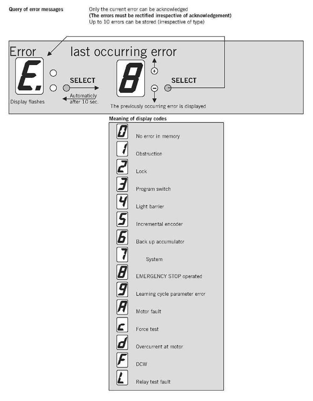
Error Code 0 – No error
Error Code 1 – Obstruction
Error Code 2 – Lock error
Error Code 3 – Program switch malfunction
Error Code 4 – Light barrier / safety sensor error
Error Code 5 – Incremental encoder malfunction
Error Code 6 – Backup battery (accumulator) failure
Error Code 7 – System error
Error Code 8 – Emergency Stop malfunction
Error Code 9 – Learning cycle parameter error
Error Code A – Motor malfunction
Error Code c – Force test failure
Error Code d – Over current at motor
Error Code F – DCW error
Error Code L – Relay test failure
General Measures:
- Set program switch to AUTOMATIC – CLOSE – AUTOMATIC.
- Power off, wait for 20 seconds, power back on.
- Run automatic learning cycle
Above measures are general solutions, real cause can be various, need carefully checking on door panels and rail, make sure the movement is smooth, and all wire connections are steady, especially good contact at the control terminals.
Reference:
- Restore ES200 original factory settings.
-
#1
Уважаемые коллеги, добрый день.
Не так давно начал заниматься обслуживанием автоматических дверей, столкнулся с такой вот проблемой:
Блок управления выходил в ошибку по аккумулятору, «пошаманили», все заработало. Но вчера сотрудник помещения нажал на стоповую кнопку, после разблокировки кнопки на блоке управления так и осталась висеть ошибка 8. Ошибку сбросили, запустили цикл обучения, все гуд все работает, но… Через минут 15 опять ошибка 8, кнопку отключили, сделали перемычку, все заработало, но…. минут через 15 опять та же ситуация, в данный момент не могу сказать какая ошибка там повисла, т.к. уехали с места работы. Но как говорят сотрудники, дверь отрабатывает некоторое время и остается в открытом положении, поворотом ключа сбрасывают ошибку и опять все по новой , несколько циклов и стоп.
Подскажите что можно сделать, и что может быть за причина, вызвавшая такой сбой.
С Уважением!
-
#2
Нашел несколько рекомендаций на просторах интернета, пока не знаю какая ошибка висит — все они актуальны:
- проверить сигнал с радара, проверить аккумулятор;
- проверить двигатель, редуктор и энкодер;
- щетки двигателя.
Господа, вопрос: может ли глючить энкодер, не отображая соответствующую ошибку?
Может хоть подскажет кто-нибудь как DORMA ES 200 Easy на заводские установки скинуть?
-
#3
Поставьте вместо кнопки перемычку и понаблюдайте.
-
#4
Перемычка уже стоит, со вчерашнего дня, толку нет! Двери встают отработав n-ое количество циклов.
Неужели никто не сталкивался с такой ситуацией? Поделитесь опытом. Сейчас любая информация поможет по теме.
-
#5
Была похожая ситуация, но не на Дорме:
После некоторого времени работы двери останавливались в открытом положении. После перезагрузки вновь некоторое время двери работали нормально и вновь останавливались.
Причина оказалась в небольшом подклинивании одной из створок в открытом состоянии, причем при прокатке руками оно не ощущалось.
Обнаружили нехарактерные потертости на нижнем направляющем профиле.
-
#6
Спасибо, будем проверять, какую-нибудь ошибку выдавал блок управления?
-
#7
Нет, на тех блоках нет индикации ошибок.
-
#8
Спасибо. Ждем-с еще комментариев по теме, может кто имел дела с приводом DORMA ES 200 Easy?
-
#9
Доброго всем дня, была ошибка аккумулятора, к тому же дверь была почему-то на заводских настройках. Отключили аккумулятор, выставили модель двигателя, пока работают, тьфу-тьфу-тьфу))) Всем спасибо за помощь))))
-
Bookmarks
Quick Links
ES 200
—
Sliding door operator
Related Manuals for Dorma ES 200
Summary of Contents for Dorma ES 200
- Page 1
ES 200 — Sliding door operator… - Page 2
Delivery formats for the implementation of new Particularly impressive is the application on the basis of just The ES 200 is available as a prefabricated MiniDriveUnit, ideas and individual concepts in a few components. The system component kit, as a complete,… - Page 3
24 V output for external accessory Opening and closing force, max. 150 N Read-out error memory with error codes Opening speed bus interface (Protokoll DORMA Connect and Work) 10 – 70 cm/s ® (incremental setting) Rechargeable battery pack for emergency operation Closing speed 10 –… - Page 4
ES 200 SLIDING DOOR OPERATOR Pulley with integrated locking device and belt tensioning device Profiles for corridor installation, 100 mm Profiles for wall installation, 100 mm Our profiles for installation heights of 100 mm and 150 mm, which are suitable for both… - Page 5
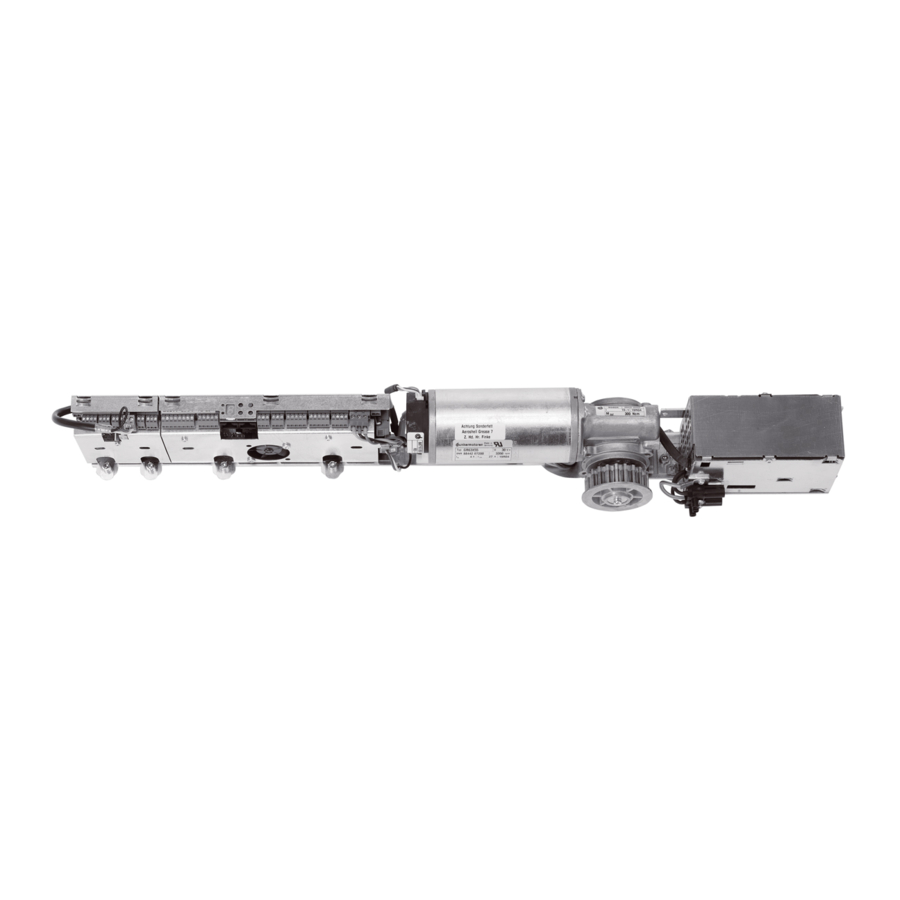
ES 200 SLIDING DOOR OPERATOR MiniDriveUnit At the core of the ES 200 Components The prefabricated MiniDriveUnit 1 MiniDriveUnit 10 Pulley (locking device) has been industrially tested with 2 Power supply unit 11 Service cover bracket all the requisite electrical and… - Page 6
ES 200 SLIDING DOOR OPERATOR THE PROFESSIONAL OPERATOR FOR INDIVIDUAL DOOR DESIGN — Door variants with ES 200, 100 mm installation height and special ”profile“ version DORMA PowerDrive System for particularly punchy performance The door variants on this page are shown as corridor installation with aluminium girder (LM). - Page 7
* Safety sensors to monitor the secondary closing edges in accordance with DIN 18650 and EN 16005 **Safety sensors to monitor the main closing edge in accordance with DIN 18650 and EN 16005 PROGRAM SWITCHES — A program switch from DORMA’s The corresponding 3-position They offer various options, from Up to 5 different functions:… -
Page 8: Push Button
ES 200 SYSTEM ACCESSORIES SWITCHES — Designation Specification Installation system Order No. On/Off switch White, aluminium, flush-mounting, 80 x 80 mm Gira S-Color 19135403150 Radar switch „MAGIC SWITCH”, proximity-type radar switch responds to movement, for flush-mounting, 80 x 80 mm…
- Page 9
ES 200 SYSTEM ACCESSORIES EMERGENCY PUSHBUTTONS — Designation Specification Installation system Order No. Designed to interrupt the automatic movement of the door, emergency pushbutton (function: Emergency Off) for automatic door operators, manufactured to ZH 1/494 or BGR 232, DIN 18650 and EN 16005, red knob with yellow centre insert, max. -
Page 10: Motion Detectors
ES 200 SYSTEM ACCESSORIES MOTION DETECTORS — Motion detectors Designation Specification Colour Order No. Prosecure Full-automatic access on pulse activation; Easy Motion adjustable inclination angle, Mono inclined field of view and field size, LED status indicator, not in accordance black…
- Page 11
ES 200 SYSTEM ACCESSORIES TRIMS AND BOXES FOR SURFACE-MOUNTED PUSHBUTTONS AND SWITCHES — Dimensions Designation Specification Installation system Order No. in mm (W x H x D) System 55 Cover frame (Programm STA) FR-S55 1 Single-type trim, Standard 55, white 80.7 x 80.7 System 55… - Page 12
DORMA Deutschland GmbH DORMA Platz 1 58256 ENNEPETAL GERMANY Phone +49 2333 793-0 +49 2333 793-4950 www.dorma.com…
-
Bookmarks
Quick Links
ES 200
—
Sliding door operator
Related Manuals for Dorma ES 200
Summary of Contents for Dorma ES 200
- Page 1
ES 200 — Sliding door operator… - Page 2
Delivery formats for the implementation of new Particularly impressive is the application on the basis of just The ES 200 is available as a prefabricated MiniDriveUnit, ideas and individual concepts in a few components. The system component kit, as a complete,… - Page 3
24 V output for external accessory Opening and closing force, max. 150 N Read-out error memory with error codes Opening speed bus interface (Protokoll DORMA Connect and Work) 10 – 70 cm/s ® (incremental setting) Rechargeable battery pack for emergency operation Closing speed 10 –… - Page 4
ES 200 SLIDING DOOR OPERATOR Pulley with integrated locking device and belt tensioning device Profiles for corridor installation, 100 mm Profiles for wall installation, 100 mm Our profiles for installation heights of 100 mm and 150 mm, which are suitable for both… - Page 5
ES 200 SLIDING DOOR OPERATOR MiniDriveUnit At the core of the ES 200 Components The prefabricated MiniDriveUnit 1 MiniDriveUnit 10 Pulley (locking device) has been industrially tested with 2 Power supply unit 11 Service cover bracket all the requisite electrical and… - Page 6
ES 200 SLIDING DOOR OPERATOR THE PROFESSIONAL OPERATOR FOR INDIVIDUAL DOOR DESIGN — Door variants with ES 200, 100 mm installation height and special ”profile“ version DORMA PowerDrive System for particularly punchy performance The door variants on this page are shown as corridor installation with aluminium girder (LM). - Page 7
* Safety sensors to monitor the secondary closing edges in accordance with DIN 18650 and EN 16005 **Safety sensors to monitor the main closing edge in accordance with DIN 18650 and EN 16005 PROGRAM SWITCHES — A program switch from DORMA’s The corresponding 3-position They offer various options, from Up to 5 different functions:… -
Page 8: Push Button
ES 200 SYSTEM ACCESSORIES SWITCHES — Designation Specification Installation system Order No. On/Off switch White, aluminium, flush-mounting, 80 x 80 mm Gira S-Color 19135403150 Radar switch „MAGIC SWITCH”, proximity-type radar switch responds to movement, for flush-mounting, 80 x 80 mm…
- Page 9
ES 200 SYSTEM ACCESSORIES EMERGENCY PUSHBUTTONS — Designation Specification Installation system Order No. Designed to interrupt the automatic movement of the door, emergency pushbutton (function: Emergency Off) for automatic door operators, manufactured to ZH 1/494 or BGR 232, DIN 18650 and EN 16005, red knob with yellow centre insert, max. -
Page 10: Motion Detectors
ES 200 SYSTEM ACCESSORIES MOTION DETECTORS — Motion detectors Designation Specification Colour Order No. Prosecure Full-automatic access on pulse activation; Easy Motion adjustable inclination angle, Mono inclined field of view and field size, LED status indicator, not in accordance black…
- Page 11
ES 200 SYSTEM ACCESSORIES TRIMS AND BOXES FOR SURFACE-MOUNTED PUSHBUTTONS AND SWITCHES — Dimensions Designation Specification Installation system Order No. in mm (W x H x D) System 55 Cover frame (Programm STA) FR-S55 1 Single-type trim, Standard 55, white 80.7 x 80.7 System 55… - Page 12
DORMA Deutschland GmbH DORMA Platz 1 58256 ENNEPETAL GERMANY Phone +49 2333 793-0 +49 2333 793-4950 www.dorma.com…
Error Code List ERROR Fan: 22 02 Cross: 00 00 RFU: 00 00 Rot.Unit: 00 00 Stacker: 00 00 Code Fan Folder error 21 Error on s<strong>te</strong>pper control board 21:01 error during start s<strong>te</strong>pper control board 21:02 error during stop s<strong>te</strong>pper control board 22 22:00 Light barrier 0 cut 22:01 Light barrier 1 cut 22:02 Light barrier 2 cut 22:03 Light barrier 3 cut 22:04 Light barrier 4 cut 23 permanent light on the receiver 23:00 receiver from LB 0 is always on high level 23:01 receiver from LB 1 is always on high level 23:02 receiver from LB 2 is always on high level 23:03 receiver from LB 3 is always on high level 23:04 receiver from LB 4 is always on high level 24 proc<strong>es</strong>sing error for s<strong>te</strong>pper control board 01 error during calcula<strong>te</strong> the s<strong>te</strong>p width 02 error during counting the s<strong>te</strong>ps 16 Example
25 Hardware error 01 lack of 5 Volt ex<strong>te</strong>rnal 02 lack of LF 38 Volt or CF door open 03 cover open 26 Jam 01 af<strong>te</strong>r cut — no signal for ready 02 af<strong>te</strong>r cut — no paper on LB 1 03 without cut signal no paper on LB 1 04 between LB 0 and LB 1 05 no paper end on LB 1 06 too many folds – document is too long 07 no end of paper on LB 0 26:08 Unexpec<strong>te</strong>d Paper on LB4 in Online-Mode 26:09 Unexpec<strong>te</strong>d Paper on “no fold” switch (LB5) in Online-Mode 27 wrong direction at last sheet folding Cross Folder error 80 Hardware error 01 lack of 5 Volt ex<strong>te</strong>rn 02 lack of LF 38 Volt or CF door open 03 lack of 28 Volt 81 Error on s<strong>te</strong>pper control board 01 error during start s<strong>te</strong>pper control board 02 error during stop s<strong>te</strong>pper control board 82 light barrier cut 82:01 LB 12 cut 82:02 LB 11 cut 82:03 LB 10 cut 17 Check voltage Check safety switch<strong>es</strong> Check voltage Check safety switch<strong>es</strong>
- Page 1 and 2: ES-TE Folding Systems GmbH Zitadell
- Page 3 and 4: Safety instructions For your protec
- Page 5 and 6: General Estefold 4211 is a fully au
- Page 7 and 8: Program number Margin width There a
- Page 9 and 10: Customize folding programs All fold
- Page 11 and 12: Rotation Unit for A2 (C-sized) Docu
- Page 13 and 14: Resolving a Paper Jam on the Bridge
- Page 15: Reinforcement Unit • Error Code 4
- Page 19 and 20: 01 xx In case of any code starting
- Page 21 and 22: Specifications Document Length 420

ES-TE
Folding Systems GmbH
Zitadellenweg 34
13599 Berlin
Telefon:
Fax:
eMail:
030 369961-3
030 369961-59
[email protected]
Internet:
www.es-te.com
Automatic inline folder
estefold 2400/2402
Purpose:
Folding of Documents
User Manual
Safety
Installation
Operation
Trouble shooting
Page 1 of 19
Edition 1.7
06.10.2008
User Manual estefold 2400/2402
Contents
Safety and important warning items ..................................................................................................................3 General ..............................................................................................................................................................7 What is the difference between 2400 and 2402 ? .............................................................................................7 Dimensions ........................................................................................................................................................8 Setting up the Folder .........................................................................................................................................9 Working with the folder ....................................................................................................................................10 Error Code .......................................................................................................................................................11 Selecting folding programs ..............................................................................................................................12 Folding programs.............................................................................................................................................12 Editing folding programs ..................................................................................................................................13 Suitable Media .................................................................................................................................................14 Suitable Formats .............................................................................................................................................14 Aligning documents .........................................................................................................................................14 Manual feeding – fan fold ................................................................................................................................15 Manual feeding – cross fold ............................................................................................................................15 Resolving a Paper Jam on the Bridge .............................................................................................................15 Resolving a Paper Jam in the Fan Folder .......................................................................................................16 Position of the Lightbarriers .............................................................................................................................17 Error Code List ................................................................................................................................................18 Change Log .....................................................................................................................................................19 Page 2 of 19
User Manual estefold 2400/2402
Safety and important warning items
Read carefully the safety and important warning items described below to understand them before
doing work.
Because of possible hazards to an inexperienced person servicing this product as well as the risk of
damage to the product, ES-TE Folding Systems (hereafter called ES-TE) strongly recommends that
all servicing be performed only by ES-TE-trained service engineer.
Changes may have been made to this product to improve its performance after this Service Manual
was printed. Accordingly, ES-TE does not warrant, either explicitly or implicitly, that the information
contained in this manual is complete and accurate.
The user of this manual must assume all risks of personal injury and/or damage to the
product while operating the product for which this manual is intended.
Therefore, this manual must be carefully read before doing work both in the course of
technical training and even after that, for performing control of the product properly.
Keep this manual always near to the folder.
Hazard Intensity Levels
DANGER: Indicates an imminently hazardous situation
which, if not avoided, WILL result in death or serious injury.
WARNING: Indicates a potentially hazardous situation which,
if not avoided, COULD result in death or serious injury.
Warning
CAUTION: Indicates a potentially hazardous situation which,
if not avoided, MAY result in minor or moderate injury.
Modifications not authorized by ES-TE
ES-TE products are renowned for their high reliability. This reliability is
achieved through high-quality design and a solid service network.
Product design is a highly complicated and delicate process where numerous mechanical, physical, and electrical aspects have to be taken
into consideration, with the aim of arriving at proper tolerances and safety
factors.
For this reason, unauthorized modifications involve a high risk of degradation in performance and safety. Such modifications are therefore
strictly prohibited. The points listed below are not exhaustive, but they
illustrate the reasoning behind this policy.
Transport
•
•
•
Move the folder only if the table is down in the transport position
(without the gas spring)
Move the machine carefully and slow with at least two persons
Any unevenness of the ground can lead to the risk of tipping
over.
Page 3 of 19
User Manual estefold 2400/2402
Prohibited Actions
•
•
•
•
•
•
Using any cables or power cord not specified by ES-TE.
Using any fuse or thermostat not specified by ES-TE. Safety will
not be assured, leading to a risk of fire and injury.
Disabling fuse functions or bridging fuse terminals with wire,
metal clips, solder or similar object.
Disabling safety functions (interlocks, safety circuits, etc.) Safety
will not be assured, leading to a risk of fire and injury.
Making any modification to the product unless instructed by ESTE
Using parts not specified by ES-TE
Power Plug Selection
-
-
-
In some countries or areas, the power plug provided with the
product may not fit wall outlet used in the area. In that case, it is
obligation of customer engineer (hereafter called the CE) to attach appropriate power plug or power cord set in order to connect the product to the supply.
Caution: Only plug the folder to power circuits which are secured
with max. 16A for Europe and max. 20A for North America.
Furthermore it is recommended to install an all-pole disconnect
device.
National installation standards have to be maintained.
Power Cord Set or Power Plug
•
Use power supply cord set which meets the following criteria:
¾
¾
¾
¾
•
provided with a plug having configuration intended for
the connection to wall outlet appropriate for the product's
rated voltage and current, and
the plug has pin/terminal(s) for grounding, and provided
with three-conductor cable having enough current capacity, and
the cord set meets regulatory requirements for the area.
Use of inadequate cord set leads to fire or electric shock.
Attach power plug which meets the following criteria:
¾
¾
¾
having configuration intended for the connection to wall
outlet appropriate for the product's rated voltage and current, and
the plug has pin/terminal(s) for grounding, and
meets regulatory requirements for the area.
Use of inadequate cord set leads to the product connecting to inadequate
power supply (voltage, current capacity, grounding), and may result in
fire or electric shock.
Page 4 of 19
Warning
User Manual estefold 2400/2402
Checkpoints when performing On-Site Service
ES-TE products are extensively tested before shipping, to ensure that all
applicable safety standards are met, in order to protect the customer and
customer engineer (hereafter called the CE) from the risk of injury. However, in daily use, any electrical equipment may be subject to parts wear
and eventual failure. In order to maintain safety and reliability, the CE
must perform regular safety checks.
Connection to Power Supply
•
•
•
•
•
•
•
•
Connect power plug directly into wall outlet having same configuration as the plug.
Use of an adapter leads to the product connecting to inadequate
power supply (voltage, current capacity, grounding), and may result in fire or electric shock.
If proper wall outlet is not available, advice the customer to contact qualified electrician for the installation.
Plug the power cord into the dedicated wall outlet with a capacity
greater than the maximum power consumption.
If excessive current flows in the wall outlet, fire may result.
If two or more power cords can be plugged into the wall outlet,
the total load must not exceed the rating of the wall outlet.
If excessive current flows in the wall outlet, fire may result.
Make sure the power cord is plugged in the wall outlet securely.
Contact problems may lead to increased resistance, overheating,
and the risk of fire.
Check whether the product is grounded properly.
If current leakage occurs in an ungrounded product, you may suffer electric shock while operating the product.
Connect power plug to grounded wall outlet.
Warning
Power Plug and Cord
•
•
•
•
•
•
•
•
When using the power cord set (inlet type) that came with this
product, make sure the connector is securely inserted in the inlet
of the product.
When securing measure is provided, secure the cord with the fixture properly.
If the power cord (inlet type) is not connected to the product securely, a contact problem may lead to increased resistance,
overheating, and risk of fire.
Check whether the power cord is not stepped on or pinched by a
table and so on. Overheating may occur there, leading to a risk
of fire.
Check whether the power cord is damaged. Check whether the
sheath is damaged. If the power plug, cord, or sheath is damaged, replace with a new power cord (with plug and connector on
each end) specified by ES-TE. Using the damaged power cord
may result in fire or electric shock.
Do not bundle or tie the power cord. Overheating may occur
there, leading to a risk of fire.
Check whether dust is collected around the power plug and wall
outlet. Using the power plug and wall outlet without removing
dust may result in fire.
Do not insert the power plug into the wall outlet with a wet hand.
Page 5 of 19
Warning
User Manual estefold 2400/2402
•
The risk of electric shock exists.
When unplugging the power cord, grasp the plug, not the cable.
The cable may be broken, leading to a risk of fire and electric
shock.
Wiring
•
•
•
Never use multi-plug adapters to plug multiple power cords in the
same outlet. If used, the risk of fire exists.
When an extension cord is required, use a specified one. Current
that can flow in the extension cord is limited, sousing a too long
extension cord may result in fire.
Do not use an extension cable reel with the cable taken up. Fire
may result.
Warning
Prohibited Installation Places
•
•
Do not place the product near flammable materials or volatile
materials that may catch fire. A risk of fire exists.
Do not place the product in a place exposed to water such as
rain. A risk of fire and electric shock exists.
Warning
When not Using the Product for a long time
•
When the product is not used over an extended period of time
(holidays, etc.), switch it off and unplug the power cord. Dust collected around the power plug and outlet may cause fire.
Warning
Stability
•
•
Be sure to set the adjustable feet on the ground.
In the case of an earthquake and so on, the product may slide,
leading to an injury.
Measures to take in case of an accident
1. If an accident has occurred, the distributor who has been notified
first must immediately take emergency measures to provide relief
to affected persons and to prevent further damage.
2. If a report of a serious accident has been received from a customer, an on-site evaluation must be carried out quickly and ESTE must be notified.
3. To determine the cause of the accident, conditions and materials
must be recorded through direct on-site checks, in accordance
with instructions issued by ES-TE.
4. For reports and measures concerning serious accidents, follow
the regulations specified by every distributor.
Page 6 of 19
User Manual estefold 2400/2402
General
Estefold 2400/2402 is an automatic folder that folds large sized plots created by any monochrome printer
according to DIN 824.
One of the 8 folding programs available can be selected by pressing a button on the folder’s keyboard.
Details of the selected program are displayed on a large LCD display that allows the folder’s easy operation.
Documents will be folded lengthwise according to the selected folding program.
The specially designed bridge takes the plot from the printer and transports it to the folder.
Documents that are not supposed to be folded will be deployed in the unfolded print bag.
In order to control the folding process, the documents pass the automatic bridge to the folder‘s inlet.
A switcher at the bridge’s entrance selects the plots that are not supposed to be folded and directs them into
the unfolded print bag.
When the plot enters the bridge it will be transported to the folder’s entrance with the exact synchronized
speed.
A sliding rail on the bridge allows documents to be fed manually. A very useful feature demonstrating the
various purposes this folder can serve.
The two gas pressure shock absorbers are supporting the bridge helping to tilt it into an almost vertical position.
In consequence of that, general access to the printer is assured.
What is the difference between 2400 and 2402 ?
The only difference between these folders is the position of Light Barrier 0.
It enables the 2402 to cover the Book Folding Style:
1st page = ½ panel.
Changing a 2400 to a 2402 is easy. Please contact the ES-TE Support Team for more information.
Page 7 of 19
User Manual estefold 2400/2402
Dimensions
Page 8 of 19
User Manual estefold 2400/2402
Setting up the Folder
Environment
The room in which the folder is to be placed should be dry and dust free.
Humidity: 20% - 80% R.H. not condensing
Room temperature: 15° C to 35° C.
The folder must stand horizontally aligned and very stable without shaking.
Always ascertain to place the folder in a way that does not block exits and allows an ergonomic workflow.
Set Up by Experts only
The set up of the folder should be done by a trained engineer in order to assure a 100 % functionality of the
folder.
Power Supply
Use delivered connecting cable only
The power supply box is at the right bottom side of the folder. Please use either the connecting cable
delivered with the folder or cables of the same safety standard only.
The folder is pre-adjusted to 230 Volts/50 cycles.
Make sure that the main supply voltage is identical with your supply.
Do not use a multi-outlet power strip. These cords will not stand the power consumption of plotter and folder.
Page 9 of 19
User Manual estefold 2400/2402
Working with the folder
Switch the folder on
The display must show a short message
as indicated.
For a short time the Firmware versions
are shown in the display.
First window:
The versions of the several components
are shown.
Second window:
The version of the Web Controller is
shown
Indicates the status of the folder
Multi color led
Red: error
Green: ready
Yellow: in operation
Page 10 of 19
User Manual estefold 2400/2402
Error Code
In case of any error during startup or
operation the folder will give a beep
signal and an error message in the display. The remaining paper will be transported out with low speed automatically
or by pressing © or ª.
To get a clear message refer to the Error Code List at the end of the user manual.
The example shows the error code 22 : 00 – this indicates that the light barrier 0 is cut. Find the light barrier
positions at page 17.
ERROR
F001,
22
00
00
00
ID2
00
00
00
00
00
00
Example
Fan folder error
21
01
02
Error on stepper control board
error during start stepper control board
error during stop stepper control board
00
01
02
03
04
Light barrier 0 cut
Light barrier 1 cut
Light barrier 2 cut
Light barrier 3 cut
Light barrier 4 cut
22
Page 11 of 19
User Manual estefold 2400/2402
Selecting folding programs
There are 8 folding programs available.
By pressing the keys © and ª you select a folding program of your own choice.
On the left hand side of the display the selected program number will appear.
The centre of the display shows an image of a folded package.
Multicolor
LED
Number of
folding program
Cross fold size
Folding Style
Width of Filing
Margin
Status:
online, offline
or manual
Panel Width
Folding programs
Factory programmed folding programs
Prog. 1
20
190
Prog. 2
190
Prog. 3
198 + strip
Prog. 4
210
The package can be applied with a tab adhesive as shown in program 3 by a separate automatic Tab
Applicator. Ask your system provider.
Page 12 of 19
User Manual estefold 2400/2402
Editing folding programs
Select Folding Style
In order to change the folding style - press - the cursor will start to blink.
Buttons ¨ and § move the cursor from icon to icon.
Selected icons blink frequently.
Pressing buttons © and ª edit the blinking settings.
Example:
Program 5 should process another folding style.
Select folding program 5 with button © or ª.
Press button
Press button ¨ until the symbol of the fold package blinks.
Press buttons © or ª in order to set the folding style
Press button within three seconds
Required Style
Icon in the display
Description
Calculated
Package folding
Calculated
Package folding
With binding margin
Uncalculated
Package folding
Calculated
Book folding
First page = ½ of panel
2402
only
Calculated
Book folding
First page = ½ of panel
With binding margin
2402
only
Uncalculated
Book folding
First page = ½ of panel
2402
only
Page 13 of 19
User Manual estefold 2400/2402
Select Size
All folding programs can be edited in increments of 1 mm within the following range:
•
•
Filing margin: 0 – 30 mm
panel width: 180 – 450 mm
In Order to change values press - the cursor will start to blink.
Buttons ¨ and § move the cursor from icon to icon.
Selected icons blink frequently.
Pressing buttons © and ª edit the blinking settings.
Example:
Program 5 should process packages 185 mm wide with a filing margin of 25 mm.
Select folding program 5 with button © or ª.
Press button
Press button ¨ until the number below the fold package icon blinks.
Press buttons © or ª in order to set the package width to 185 mm.
Move the cursor forward to the figure representing the margin width
With buttons © or ª select 25 mm.
Press button within three seconds
Please notice that the adjustable width of the package must be at least 180 mm up to a maximum of 450 mm.
The range of adjustment of the margin is 0 – 30 mm. Therefore a package of 165/35 is not adjustable.
Suitable Media
•
•
•
Film or materials with glossy shiny surfaces are not suitable.
For application of media types, please contact the service engineer.
The paperweight should not be less than 60 g/m² and not more than 110 g/m².
Suitable Formats
Fan folding up to 50m (two panels unfolded after
5m) – cross folding up to 1.50m
Longitudinal folding:
All documents with length from 420 mm up to 50.000 mm (80 gr/m² Paper) and width up to max. 930 mm.
Aligning documents
In any case the title block (legend) has to be on the leading edge of the document entering the folder (on the
right hand side of the leading edge).
The title block position has to be set in the plot software you are using.
Page 14 of 19
User Manual estefold 2400/2402
Manual feeding – fan fold
You may also insert documents into the folder manually.
For some systems you need switching the
folder “offline” on the printers display first.
to manual mode
by pressing
Switch icon
button twice.
Insert the sheet face down (title block must be in
front), aligning centrically. The insertion rail on the
table can be slid into an optimized position for the
document you are feeding. Please take care to feed
the paper as straight as possible.
Manual feeding – cross fold
Insert the sheet face up (title block must be in front).
Please take care to feed the paper as straight as
possible.
Change the cross fold size:
In Order to change the cross fold size press - the cursor will start to blink.
Buttons ¨ and § move the cursor from icon to icon.
Selected icons blink frequently. Select the number below the cross fold symbol.
Pressing buttons © and ª edit the blinking settings.
Press button within three seconds
Resolving a Paper Jam on the Bridge
The LED on top of the display shining red and a blinking icon for the fan folded document indicates an error
either on the bridge or in the fan folder. After pressing button once, the display shows an error code indicating type and location of the error. The most probable cause for a cut light barrier is that there is still a
whole or a part of a document on the bridge. In order to remove the document on the bridge you lift the bridge
cover by gripping it at the edge.
Page 15 of 19
As soon as you have lifted the cover, you may lock it
in the raised position by extending the suspending
link.
You can now inspect the bridges inside and remove
any paper leftovers.
As soon as the leftovers have been removed, the
cover needs to be closed.
Press button once in order to commence your job.
Suspending Link
You may have to call for a service engineer in case
paper was not the cause to the error.
Resolving a Paper Jam in the Fan Folder
Lift Top Cover
Here
The LED on top of the display shining red and a
blinking icon for the fan folded document indicates an
error either on the bridge or in the fan folder. After
pressing button once, the display shows an error
code indicating type and location of the error.
The most probable cause for a cut light barrier is that
there is still a whole or a part of a document in the
fan folder.
In order to remove the document in the fan folder you
have to lift the fan folder top cover.
Rotate this roller manually in
order to remove jammed
documents
Safety Switch Fan Folder
The folder will be powered off as a safety switch on the
top cover cuts power at the same instance.
As soon as you have lifted the cover, you will see the fan
folder’s inside. Retrieve documents stuck between the fold
rollers by simply turning the fold rollers manually.
The paper pieces will appear either at the folder’s top or its
rear depending on the direction you are rotating the fold
rollers.
Page 16 of 19
Position of the Lightbarriers
Close the top cover as soon as the leftovers have been removed. Press button once in order to commence your job.
You may have to call for a service engineer in case either paper was not the cause to the error or you were not able to
retrieve all of the paper.
Page 17 of 19
Error Code List
ERROR
22
Fan:
Cross:
00
RFU:
00
Rot.Unit: 00
Stacker: 00
Code
02
00
00
00
00
Example
Fan folder error
21
cause
01
Error on stepper control board
error during start stepper control board
•
02
error during stop stepper control board
•
38V lost on board (green led on
stepper control board is off)
internal logic error
00
01
02
03
04
Light barrier 0 cut
Light barrier 1 cut
Light barrier 2 cut
Light barrier 3 cut
Light barrier 4 cut
•
•
•
Paper between LB and prism
cable broken
Light barrier defective
•
•
•
Direct reflection from sender to
receiver
dust on sender, receiver or prism
Port on PCB damaged
22
23
04
permanent light on the receiver
receiver from LB 0 is always on high
level
receiver from LB 1 is always on high
level
receiver from LB 2 is always on high
level
receiver from LB 3 is always on high
level
receiver from LB 4 is always on high
level
01
02
processing error for stepper control board
error during calculate the step width
error during counting the steps
•
•
mostly electrostatic
developer tool
01
02
03
Hardware error
lack of 5 Volt external
lack of LF 38 Volt or CF door open
ff cover open
•
•
•
Check fuses and connectors
fan folder: top cover open
cross folder: door open
•
•
•
•
•
•
•
Jam on the printer’s knife
Jam on the bridge
Jam on the bridge
Jam in the fan folder
Jam in the fan folder
copy too long
Jam at output fan folder
•
Switch to offline mode
•
defective LB
00
01
02
03
24
25
26
01
02
03
04
05
06
07
08
09
27
Jam
after cut - no signal for ready
after cut - no paper on LB 1
without cut signal no paper on LB 1
between LB 0 and LB 1
not paper end on LB 1
too many folds
no end of paper on LB 0
Unexpected Paper on LB4 in OnlineMode
Unexpected Paper on “no fold” switch
(LB5)
in Online-Mode
wrong direction at last sheet folding
Page 18 of 19
Change Log
Date
Subject
Author
Edition
06.03.2007
•
Creation
P. Legarth
1.0
02.07.2007
•
Error code list 1.7
o Page 14
Safety and warning
o Page 3
Integration cross fold
o Page10
Editorial changes
P. Legarth
1.1
Editorial changes
Dimensions picture changed
Change cross fold size
o Page 14
Error Code List replaced
Cross fold “face up” instead “face down”
o Page 14
2402
Book folding implemented
P. Legarth
P. Legarth
P. Legarth
1.2
1.3
1.4
P. Legarth
P. Legarth
1.5
1.6
P.Legarth
1.7
•
•
•
17.07.2007
21.09.2007
05.10.2007
•
•
•
18.03.2008
07.07.2008
•
•
06.10.2008
•
•
Page 19 of 19
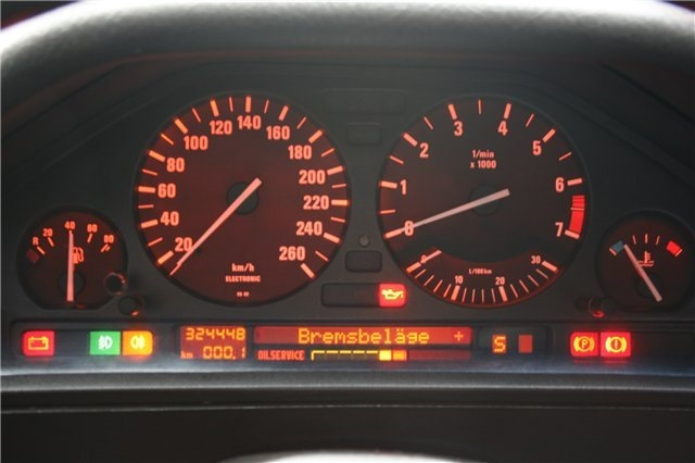
Фото из интернета. Свои ошибки к счастью пропали)
И снова здравствуйте. Отгремели выборы и нужно дальше вести БЖ. Ооооочень долго меня нервировали следующие ошибки на приборной панели:
Abblendlicht [DIP BEAM] — накрылся ближний свет.
Rucklicht [TAIL LIGHT] — один из задних габаритов не горит.
Kennzeichenlicht [LIC PLATE LT] — одна или обе лампы подсветки номера не горят.
Betriebsanleitung [OWNER’S HANDBOOK] — читайте инструкцию к автомобилю.
Kein Bremslicht [BREAK LIGHT] — отсутствует стоп-сигнал. Редко лампы горят по две.
И если первые четыре высвечивались только после включения зажигания и дальше никак себя не выдавали, то [BREAK LIGHT] выскакивала как ей вздумается и никакой логике не поддавалась. Хочу сразу заметить что перед тем как найти решение для этих ошибок я проделал следующие манипуляции:
1. Пару раз менял производителя ламп ближнего света (ставил всегда галоген соответствующий параметрам заводских) — не помогло
2. Пару раз менял лампочки габаритов на разных производителей согласно номиналам завода — не помогло
3. Менял лампочки подсветки номера на обычные, светодиодные и тд. и тп. — не помогло
4. Менял патроны ламп и сами лампы согласно номиналу завода на стопарях — не помогло
5. Много раз чистил везде контакты от окисления, прозванивал проводку, смотрел преды и тд. — тоже не помогло.
Собственно единственное что бесило это ошибка по стопарям ибо она выскакивала хаотично, могла не появляться 2 дня, могла загораться сразу после первого нажатия на педаль и самое бесячее, что эта ошибка никак не сбрасывается и пользование функциями БК было не возможно.
Теперь самое главное. Способы решения данных проблем. Есть два способа решения:
1. Замена блока CCM под капотом в коробке с предохранителями. Тут есть много нюансов: есть несколько видов блоков и нужно выбирать тот который стоит у вас по номеру, нужно прошивать этот блок на ваш вин и пробег ибо в противном случае будет гореть лампа «скрутки пробега» посередине приборки.
2. Второй способ который помог мне избавиться от всех этих ошибок. Сразу скажу, что данный способ ооочень бредовый и на первый взгляд (да и на второй и третий тоже) кажется абсолютно абсурдным. Я тоже так считал до этой субботы. В общем нужно отключить фишки с ЭЛЕКТРО КОРРЕКТОРОВ ФАР (либо поочередно и выявить какой из них моросит). Вот такие вот пироги. Лично мне помогло).
-
Hello,
Our Polar cutter recently stopped working in the middle of a job. The light barrier indicates that there’s an obstruction, but no such obstruction exists. We’ve had this problem before, and subtle re-alignment has fixed it in the past, but now nothing I do can get any indicator lights (except D5 and D6) to come on. I’ve cleaned everything to remove potential dust, I can’t find any loose wires, and nothing appears to be physically wrong with it.
I’m wondering what else there is to do. Is there a part internal to the machine that often goes bad or gets jostled out of position? Is there an official method/process for properly aligning the two arms (as might happen during installation)? What diagnostics can I perform to find out where this problem is coming from?
Thank you
-
Hi sir:
If you test everything, please take care about Oxide pins in connector, try to clean with Contacts Cleaner Spray for electronic.2) You must test the power supply : a) in transmitter for +24Vdc with tolerance 3% up or down. b) in +12Vdc in the receiver side, with 3% of tolerance up or down.
3) If the power supply is defective or is higher or down with the parameters of tolerance, go the power supply electronic board ps10, and take the test properly and carefully.
-
Vako
New Member
- Joined:
- Jun 2021
- Messages:
- 4
- Location:
- Israel
Happened exactly same story , just after changing oil , after 15 minute cutter stopped ,
What could make the problem I have no idea ((
(( -
Hi Sir;
1) Test the power supply x + 24Vdc +12 Vdc in the Power supply electronic board, must be in tolerance with 0.7% up or down.otherwise you must repair or replace it.!!!!
2)
The light barrier is supplied with 24 Vd.c. on the transmitter side and 24 Vd.c. as well as 12 Vd.c. on
the receiver side., tested very well the power supply, and look very well the connector look for plug 600.8+9, can be loose, corroded, or loose pins, or dirty with oil, etc
Use special contacts cleaner for Electronic.3)V83 red Safety lever (YSB) in the BOAR SK 95 , SEE if THE led color RED v83 Basic condition OFF (before to push cut button)
Error Code List ERROR Fan: 22 02 Cross: 00 00 RFU: 00 00 Rot.Unit: 00 00 Stacker: 00 00 Code Fan Folder error 21 Error on s<strong>te</strong>pper control board 21:01 error during start s<strong>te</strong>pper control board 21:02 error during stop s<strong>te</strong>pper control board 22 22:00 Light barrier 0 cut 22:01 Light barrier 1 cut 22:02 Light barrier 2 cut 22:03 Light barrier 3 cut 22:04 Light barrier 4 cut 23 permanent light on the receiver 23:00 receiver from LB 0 is always on high level 23:01 receiver from LB 1 is always on high level 23:02 receiver from LB 2 is always on high level 23:03 receiver from LB 3 is always on high level 23:04 receiver from LB 4 is always on high level 24 proc<strong>es</strong>sing error for s<strong>te</strong>pper control board 01 error during calcula<strong>te</strong> the s<strong>te</strong>p width 02 error during counting the s<strong>te</strong>ps 16 Example
25 Hardware error 01 lack of 5 Volt ex<strong>te</strong>rnal 02 lack of LF 38 Volt or CF door open 03 cover open 26 Jam 01 af<strong>te</strong>r cut — no signal for ready 02 af<strong>te</strong>r cut — no paper on LB 1 03 without cut signal no paper on LB 1 04 between LB 0 and LB 1 05 no paper end on LB 1 06 too many folds – document is too long 07 no end of paper on LB 0 26:08 Unexpec<strong>te</strong>d Paper on LB4 in Online-Mode 26:09 Unexpec<strong>te</strong>d Paper on “no fold” switch (LB5) in Online-Mode 27 wrong direction at last sheet folding Cross Folder error 80 Hardware error 01 lack of 5 Volt ex<strong>te</strong>rn 02 lack of LF 38 Volt or CF door open 03 lack of 28 Volt 81 Error on s<strong>te</strong>pper control board 01 error during start s<strong>te</strong>pper control board 02 error during stop s<strong>te</strong>pper control board 82 light barrier cut 82:01 LB 12 cut 82:02 LB 11 cut 82:03 LB 10 cut 17 Check voltage Check safety switch<strong>es</strong> Check voltage Check safety switch<strong>es</strong>
- Page 1 and 2: ES-TE Folding Systems GmbH Zitadell
- Page 3 and 4: Safety instructions For your protec
- Page 5 and 6: General Estefold 4211 is a fully au
- Page 7 and 8: Program number Margin width There a
- Page 9 and 10: Customize folding programs All fold
- Page 11 and 12: Rotation Unit for A2 (C-sized) Docu
- Page 13 and 14: Resolving a Paper Jam on the Bridge
- Page 15: Reinforcement Unit • Error Code 4
- Page 19 and 20: 01 xx In case of any code starting
- Page 21 and 22: Specifications Document Length 420
#1
![]()
vec
-
- Постоянные посетители
-
- Cообщений: 30
Начинающий Опелевод

- Город:Саратов
- Автомобиль: opel vectra С 1.6,2007г.в.
- @Упоминание
Отправлено 24 Январь 2010 — 22:21
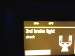
Всем привет! Подскажите, что обозначает надпись (3rd brake light check) на БК. Это у меня уже пару раз повторяется, при попытки завестись. На БК нарисован капот с фарами,а из под капота ,середины луч. При второй попытке всё становиться нормально. зарание спасибо. 
Прикрепленные изображения
#2
![]()
berkut
berkut
-
- Клубные пользователи
-
- Cообщений: 15 232
Опелевод со стажем

- Город:Москва, ТиНАО, ПБ
- Автомобиль: 1,8 (LPG)
- @Упоминание
Отправлено 24 Январь 2010 — 22:24
vec, стоп сигнал на крыше, машина сама написала, а водитель не понял.
разгадывание авто»электро головоломок», ремонт и восстановление электропроводки без пайки и скруток, поиск обрывов и потерявшихся сигналов, убирание «соплей» и пр.
Денис
#3
![]()
vec
vec
-
- Постоянные посетители
-
- Cообщений: 30
Начинающий Опелевод
- Город:Саратов
- Автомобиль: opel vectra С 1.6,2007г.в.
- @Упоминание
Отправлено 24 Январь 2010 — 22:44
Цитата(berkut @ 24.1.2010, 22:24)
vec, стоп сигнал на крыше, машина сама написала, а водитель не понял.
ну спасибо «Добр человек». А нормально?
#4
![]()
Impreza STI
Impreza STI
-
- Клубные пользователи
-
- Cообщений: 3 287
Опелевод со стажем
- Город:МО
- @Упоминание
Отправлено 24 Январь 2010 — 22:54
Цитата(berkut @ 24.1.2010, 22:24)
vec, стоп сигнал на крыше, машина сама написала, а водитель не понял.
Точнее неисправность дополнительного (3-его) фонаря стоп сигналов, который на крышке багажника.
Диагностика и ремонт Адам Опель GmbH
Wild Wild West ®
#5
![]()
PILZ
PILZ
- Город:МО, г. Пушкино
- Интересы:Автомобили, музыка, работа, семья
- Автомобиль: Vectra C
- @Упоминание
Отправлено 24 Январь 2010 — 23:41
vec,
третий стоп-сигнал состоит из светодиодов , когда хотябы через один диод не проходит ток из-за слабого контакта, то выкидывает такую ошибку. при повторном нажатии на педаль тормоза контакт диода замыкается полностью и ошибка исчезает…
у меня такая хрень уже 2 года и я знаю из-за какого диода, вот собираюсь разобрать и проверить все контакты, при неисправности их запаять….
советую сделать тоже самое….
…дни летят как мухи на г….
#6
![]()
vec
vec
-
- Постоянные посетители
-
- Cообщений: 30
Начинающий Опелевод
- Город:Саратов
- Автомобиль: opel vectra С 1.6,2007г.в.
- @Упоминание
Отправлено 24 Январь 2010 — 23:46
Цитата(Impreza STI @ 24.1.2010, 22:54)
Точнее неисправность дополнительного (3-его) фонаря стоп сигналов, который на крышке багажника.
Большое спасибо!!! Теперь будем знать. 
Цитата(PILZ @ 24.1.2010, 23:41)
vec,
третий стоп-сигнал состоит из светодиодов , когда хотябы через один диод не проходит ток из-за слабого контакта, то выкидывает такую ошибку. при повторном нажатии на педаль тормоза контакт диода замыкается полностью и ошибка исчезает…
у меня такая хрень уже 2 года и я знаю из-за какого диода, вот собираюсь разобрать и проверить все контакты, при неисправности их запаять….
советую сделать тоже самое….
Благодарю
#7
![]()
WarDob
WarDob
- Город:Москва, Люблино и МО, Пушкино
- Автомобиль: Opel Vectra C 2.0t
- @Упоминание
Отправлено 25 Январь 2010 — 00:08
vec, тоже такое иногда бывает. Фигня это всё, PILZ всё правильно написал. Если не доверяете компу — попросите, чтобы посмотрели горят ли стопы.
Opel Vectra C, Z20NET, 2007, black sapphire, cosmo + пакеты Premium и Attractive, Opera CDC 40.
#8
![]()
maxx1981
maxx1981
-
- Постоянные посетители
- Cообщений: 3
Читатель

- Автомобиль: opel Signum 3.2
- @Упоминание
Отправлено 25 Январь 2010 — 11:03
А у меня похожая ситуация. Только пишет — Check rear left(right) brake light. И так при кажодм включении. Хотя стоп-сигналы все работают. Что за фигня?1
#9
![]()
Impreza STI
Impreza STI
-
- Клубные пользователи
-
- Cообщений: 3 287
Опелевод со стажем
- Город:МО
- @Упоминание
Отправлено 25 Январь 2010 — 11:10
Цитата(maxx1981 @ 25.1.2010, 11:03)
А у меня похожая ситуация. Только пишет — Check rear left(right) brake light. И так при кажодм включении. Хотя стоп-сигналы все работают. Что за фигня?1
Замените лампы стоп сигналов на хорошие типа Osram или Philips и проблема уйдет!
Диагностика и ремонт Адам Опель GmbH
Wild Wild West ®
#10
![]()
iyod
iyod
-
- Постоянные посетители
- Cообщений: 3
Читатель
- Автомобиль: Vectra
- @Упоминание
Отправлено 26 Январь 2010 — 01:45
А я только месяц назад заменил лампочку ближнего света, так вчера она опять гореть перестала. Можно списать всё на мороз, но могла бы перегореть хоть другая — правая, к примеру. А ведь менял на сервисе, так они заломили мне 1500 вместе с работой (типа чуть ли не бампер надо откручивать, что бы её поменять — это что, правда? Кто знает?).
СТРАННО, что я нигде не встретил обсуждения на такую тему!!! Из основных претензий к этой машине (а у меня их уж очень много скопилось за полтора года эксплуатации — продать хочу — не легла душа Объективно) — это захлёбывание бензонасоса при наличии в баке бензина, особенно при движении в горку. Ну какого хрена, скажите (это я в официале вопрос задаю), при ещё не полученном оповещении компа о минимуме бензина (на 40-45км. пишет, что ещё осталось), должен не совершать, например обгона, т.к. рискую жизнью и здоровьем при совершении манёвра, из за того, что бензонасос не утоплен полностью в бензин и машина дёргается и чихает. Повторяю, стрелка ещё далеко не в красной зоне (да если бы и в красной — ЭТО МОЙ БЕНЗИН)!!! Да, с гордостью отвечает мне представитель Опель, так сделано специально, чтобы насос не перегревался. .мы говорит, ни одного насоса не поменяли по гарантии. А я считаю, что это явная угроза моей безопасности. Кто может сказать, так ли у вас? И если да, то ваше мнение? ps. Я ездил на многих машинах и ни на одной не было такой особенности. ps2. Простите, если я не в том месте форума завел разговор на эту тему (только что зарегистрировался и не слишком-то ориентируюсь).
#11
![]()
KMFDM
KMFDM
-
- Постоянные посетители
-
- Cообщений: 12
Начинающий Опелевод
- Автомобиль: Vectra C Z22SE бензин, автомат
- @Упоминание
Отправлено 26 Январь 2010 — 09:33
Цитата(iyod @ 26.1.2010, 1:45)
А я только месяц назад заменил лампочку ближнего света, так вчера она опять гореть перестала. Можно списать всё на мороз, но могла бы перегореть хоть другая — правая, к примеру. А ведь менял на сервисе, так они заломили мне 1500 вместе с работой (типа чуть ли не бампер надо откручивать, что бы её поменять — это что, правда? Кто знает?).
СТРАННО, что я нигде не встретил обсуждения на такую тему!!! Из основных претензий к этой машине (а у меня их уж очень много скопилось за полтора года эксплуатации — продать хочу — не легла душа Объективно) — это захлёбывание бензонасоса при наличии в баке бензина, особенно при движении в горку. Ну какого хрена, скажите (это я в официале вопрос задаю), при ещё не полученном оповещении компа о минимуме бензина (на 40-45км. пишет, что ещё осталось), должен не совершать, например обгона, т.к. рискую жизнью и здоровьем при совершении манёвра, из за того, что бензонасос не утоплен полностью в бензин и машина дёргается и чихает. Повторяю, стрелка ещё далеко не в красной зоне (да если бы и в красной — ЭТО МОЙ БЕНЗИН)!!! Да, с гордостью отвечает мне представитель Опель, так сделано специально, чтобы насос не перегревался. .мы говорит, ни одного насоса не поменяли по гарантии. А я считаю, что это явная угроза моей безопасности. Кто может сказать, так ли у вас? И если да, то ваше мнение? ps. Я ездил на многих машинах и ни на одной не было такой особенности. ps2. Простите, если я не в том месте форума завел разговор на эту тему (только что зарегистрировался и не слишком-то ориентируюсь).
Для того, чтобы поменять лампочку не надо бампер откручивать, просто её не очень удобно вставлять, посмотрите по-внимательнее на блок фару, там несколько кожухов сзади, открываете нужный и вставляете лампочку….. з.ы. а у официалов всегда дорогая замена лампочек, дешевле самому…
#12
![]()
Antony_87
Antony_87
-
- Клубные пользователи
-
- Cообщений: 3 246
Опелевод со стажем
- Город:Москва, Жуковский
- Автомобиль: OVC GTS 07 Z18XER 5MT
- @Упоминание
Отправлено 26 Январь 2010 — 13:45
замена лампочки правой фары по инструкции эксплуатации — со сьемом фары поэтому дорого
все фигня кроме пчел, да и пчелы тоже фигня
#13
![]()
KMFDM
KMFDM
-
- Постоянные посетители
-
- Cообщений: 12
Начинающий Опелевод
- Автомобиль: Vectra C Z22SE бензин, автомат
- @Упоминание
Отправлено 26 Январь 2010 — 14:17
Цитата(Antony_87 @ 26.1.2010, 13:45)
замена лампочки правой фары по инструкции эксплуатации — со сьемом фары поэтому дорого
как-будто кто-то эту инструкцию соблюдает……… сам работал у официалов, знаю
#14
![]()
PILZ
PILZ
- Город:МО, г. Пушкино
- Интересы:Автомобили, музыка, работа, семья
- Автомобиль: Vectra C
- @Упоминание
Отправлено 26 Январь 2010 — 14:58
iyod,
лампа в правой фаре меняется сложнее, чем в левой, но без снятия бампера, нужно просто неудобно выгнуть руку. а от частого перегорания и для лучшей освещённости дороги я поставил ксенон. с бензонасосом таких проблем не возникало, качает даже когда стрелка в красной зоне и в баке остаётся литров 10 по показаниям БК, видимо насос менялся и не был корректно установлен…ИМХО
…дни летят как мухи на г….
#15
![]()
Antony_87
Antony_87
-
- Клубные пользователи
-
- Cообщений: 3 246
Опелевод со стажем
- Город:Москва, Жуковский
- Автомобиль: OVC GTS 07 Z18XER 5MT
- @Упоминание
Отправлено 26 Январь 2010 — 15:27
2 KMFDM
соблюдают или нет — не суть
если замена лампы по справочнику около 1 нормочаса (или 0.5 часа — не помню) — будет соответствующая цена
а как вы там ее поменяете со сьемом фары или со сьемом двигателя — это уже на цену особо не влияет 
Сообщение отредактировал Antony_87: 26 Январь 2010 — 15:27
все фигня кроме пчел, да и пчелы тоже фигня
#16
![]()
alexm
alexm
-
- Постоянные посетители
-
- Cообщений: 11
Начинающий Опелевод
- Город:СПб
- Автомобиль: Vectra C 2008
- @Упоминание
Отправлено 09 Февраль 2010 — 08:06
Менял лампы ближнего света в обоих фарах: в левой — для удобства доступа снимается горловина бачка незамерзайки, в правой — пришлось немного отодвинуть воздушник. На всю замену ушло десять минут. А задний третий стопарь тоже постоянно глючит, но потом ошибка исчезает, так что я на это дело забил.

-
#7
Las fotos son para saber que tipo de sensores lleva , barrera , reflexivos , vista de rayos X , etc !

Fogonazo
«Qualified exorcist approved by the Vatican»
-
#9
Estos son los 4 sensores de arriba. Abajo hay otro igual. En la otra imágen está el sensor. . .
Y ¿ Que tal unas imágenes donde se pueda llegar a ver algo ?
-
#11
Puede que sean sensores capacitivos, sería interesante que quites esa placa y tome una foro en la que se pueda ver bien lo que tiene por el otro lado
MCS son las siglas de Movile Control System SA
Última edición: Oct 12, 2018
Error codes (fault codes) reference of ES200 automatic door malfunctions (Dorma ES200 applicable).
ERROR CODES (FAULT CODES) REFERENCE – ES200
Error Code 0 – No error
Error Code 1 – Obstruction
Error Code 2 – Lock error
Error Code 3 – Program switch malfunction
Error Code 4 – Light barrier / safety sensor error
Error Code 5 – Incremental encoder malfunction
Error Code 6 – Backup battery (accumulator) failure
Error Code 7 – System error
Error Code 8 – Emergency Stop malfunction
Error Code 9 – Learning cycle parameter error
Error Code A – Motor malfunction
Error Code c – Force test failure
Error Code d – Over current at motor
Error Code F – DCW error
Error Code L – Relay test failure
General Measures:
- Set program switch to AUTOMATIC – CLOSE – AUTOMATIC.
- Power off, wait for 20 seconds, power back on.
- Run automatic learning cycle
Above measures are general solutions, real cause can be various, need carefully checking on door panels and rail, make sure the movement is smooth, and all wire connections are steady, especially good contact at the control terminals.
Reference:
- Restore ES200 original factory settings.
-
#1
Уважаемые коллеги, добрый день.
Не так давно начал заниматься обслуживанием автоматических дверей, столкнулся с такой вот проблемой:
Блок управления выходил в ошибку по аккумулятору, «пошаманили», все заработало. Но вчера сотрудник помещения нажал на стоповую кнопку, после разблокировки кнопки на блоке управления так и осталась висеть ошибка 8. Ошибку сбросили, запустили цикл обучения, все гуд все работает, но… Через минут 15 опять ошибка 8, кнопку отключили, сделали перемычку, все заработало, но…. минут через 15 опять та же ситуация, в данный момент не могу сказать какая ошибка там повисла, т.к. уехали с места работы. Но как говорят сотрудники, дверь отрабатывает некоторое время и остается в открытом положении, поворотом ключа сбрасывают ошибку и опять все по новой , несколько циклов и стоп.
Подскажите что можно сделать, и что может быть за причина, вызвавшая такой сбой.
С Уважением!
-
#2
Нашел несколько рекомендаций на просторах интернета, пока не знаю какая ошибка висит — все они актуальны:
- проверить сигнал с радара, проверить аккумулятор;
- проверить двигатель, редуктор и энкодер;
- щетки двигателя.
Господа, вопрос: может ли глючить энкодер, не отображая соответствующую ошибку?
Может хоть подскажет кто-нибудь как DORMA ES 200 Easy на заводские установки скинуть?
-
#3
Поставьте вместо кнопки перемычку и понаблюдайте.
-
#4
Перемычка уже стоит, со вчерашнего дня, толку нет! Двери встают отработав n-ое количество циклов.
Неужели никто не сталкивался с такой ситуацией? Поделитесь опытом. Сейчас любая информация поможет по теме.
-
#5
Была похожая ситуация, но не на Дорме:
После некоторого времени работы двери останавливались в открытом положении. После перезагрузки вновь некоторое время двери работали нормально и вновь останавливались.
Причина оказалась в небольшом подклинивании одной из створок в открытом состоянии, причем при прокатке руками оно не ощущалось.
Обнаружили нехарактерные потертости на нижнем направляющем профиле.
-
#6
Спасибо, будем проверять, какую-нибудь ошибку выдавал блок управления?
-
#7
Нет, на тех блоках нет индикации ошибок.
-
#8
Спасибо. Ждем-с еще комментариев по теме, может кто имел дела с приводом DORMA ES 200 Easy?
-
#9
Доброго всем дня, была ошибка аккумулятора, к тому же дверь была почему-то на заводских настройках. Отключили аккумулятор, выставили модель двигателя, пока работают, тьфу-тьфу-тьфу))) Всем спасибо за помощь))))
-
Bookmarks
Quick Links
ES 200
—
Sliding door operator
Related Manuals for Dorma ES 200
Summary of Contents for Dorma ES 200
- Page 1
ES 200 — Sliding door operator… - Page 2
Delivery formats for the implementation of new Particularly impressive is the application on the basis of just The ES 200 is available as a prefabricated MiniDriveUnit, ideas and individual concepts in a few components. The system component kit, as a complete,… - Page 3
24 V output for external accessory Opening and closing force, max. 150 N Read-out error memory with error codes Opening speed bus interface (Protokoll DORMA Connect and Work) 10 – 70 cm/s ® (incremental setting) Rechargeable battery pack for emergency operation Closing speed 10 –… - Page 4
ES 200 SLIDING DOOR OPERATOR Pulley with integrated locking device and belt tensioning device Profiles for corridor installation, 100 mm Profiles for wall installation, 100 mm Our profiles for installation heights of 100 mm and 150 mm, which are suitable for both… - Page 5
ES 200 SLIDING DOOR OPERATOR MiniDriveUnit At the core of the ES 200 Components The prefabricated MiniDriveUnit 1 MiniDriveUnit 10 Pulley (locking device) has been industrially tested with 2 Power supply unit 11 Service cover bracket all the requisite electrical and… - Page 6
ES 200 SLIDING DOOR OPERATOR THE PROFESSIONAL OPERATOR FOR INDIVIDUAL DOOR DESIGN — Door variants with ES 200, 100 mm installation height and special ”profile“ version DORMA PowerDrive System for particularly punchy performance The door variants on this page are shown as corridor installation with aluminium girder (LM). - Page 7
* Safety sensors to monitor the secondary closing edges in accordance with DIN 18650 and EN 16005 **Safety sensors to monitor the main closing edge in accordance with DIN 18650 and EN 16005 PROGRAM SWITCHES — A program switch from DORMA’s The corresponding 3-position They offer various options, from Up to 5 different functions:… -
Page 8: Push Button
ES 200 SYSTEM ACCESSORIES SWITCHES — Designation Specification Installation system Order No. On/Off switch White, aluminium, flush-mounting, 80 x 80 mm Gira S-Color 19135403150 Radar switch „MAGIC SWITCH”, proximity-type radar switch responds to movement, for flush-mounting, 80 x 80 mm…
- Page 9
ES 200 SYSTEM ACCESSORIES EMERGENCY PUSHBUTTONS — Designation Specification Installation system Order No. Designed to interrupt the automatic movement of the door, emergency pushbutton (function: Emergency Off) for automatic door operators, manufactured to ZH 1/494 or BGR 232, DIN 18650 and EN 16005, red knob with yellow centre insert, max. -
Page 10: Motion Detectors
ES 200 SYSTEM ACCESSORIES MOTION DETECTORS — Motion detectors Designation Specification Colour Order No. Prosecure Full-automatic access on pulse activation; Easy Motion adjustable inclination angle, Mono inclined field of view and field size, LED status indicator, not in accordance black…
- Page 11
ES 200 SYSTEM ACCESSORIES TRIMS AND BOXES FOR SURFACE-MOUNTED PUSHBUTTONS AND SWITCHES — Dimensions Designation Specification Installation system Order No. in mm (W x H x D) System 55 Cover frame (Programm STA) FR-S55 1 Single-type trim, Standard 55, white 80.7 x 80.7 System 55… - Page 12
DORMA Deutschland GmbH DORMA Platz 1 58256 ENNEPETAL GERMANY Phone +49 2333 793-0 +49 2333 793-4950 www.dorma.com…
Error Code List ERROR Fan: 22 02 Cross: 00 00 RFU: 00 00 Rot.Unit: 00 00 Stacker: 00 00 Code Fan Folder error 21 Error on s<strong>te</strong>pper control board 21:01 error during start s<strong>te</strong>pper control board 21:02 error during stop s<strong>te</strong>pper control board 22 22:00 Light barrier 0 cut 22:01 Light barrier 1 cut 22:02 Light barrier 2 cut 22:03 Light barrier 3 cut 22:04 Light barrier 4 cut 23 permanent light on the receiver 23:00 receiver from LB 0 is always on high level 23:01 receiver from LB 1 is always on high level 23:02 receiver from LB 2 is always on high level 23:03 receiver from LB 3 is always on high level 23:04 receiver from LB 4 is always on high level 24 proc<strong>es</strong>sing error for s<strong>te</strong>pper control board 01 error during calcula<strong>te</strong> the s<strong>te</strong>p width 02 error during counting the s<strong>te</strong>ps 16 Example
25 Hardware error 01 lack of 5 Volt ex<strong>te</strong>rnal 02 lack of LF 38 Volt or CF door open 03 cover open 26 Jam 01 af<strong>te</strong>r cut — no signal for ready 02 af<strong>te</strong>r cut — no paper on LB 1 03 without cut signal no paper on LB 1 04 between LB 0 and LB 1 05 no paper end on LB 1 06 too many folds – document is too long 07 no end of paper on LB 0 26:08 Unexpec<strong>te</strong>d Paper on LB4 in Online-Mode 26:09 Unexpec<strong>te</strong>d Paper on “no fold” switch (LB5) in Online-Mode 27 wrong direction at last sheet folding Cross Folder error 80 Hardware error 01 lack of 5 Volt ex<strong>te</strong>rn 02 lack of LF 38 Volt or CF door open 03 lack of 28 Volt 81 Error on s<strong>te</strong>pper control board 01 error during start s<strong>te</strong>pper control board 02 error during stop s<strong>te</strong>pper control board 82 light barrier cut 82:01 LB 12 cut 82:02 LB 11 cut 82:03 LB 10 cut 17 Check voltage Check safety switch<strong>es</strong> Check voltage Check safety switch<strong>es</strong>
- Page 1 and 2: ES-TE Folding Systems GmbH Zitadell
- Page 3 and 4: Safety instructions For your protec
- Page 5 and 6: General Estefold 4211 is a fully au
- Page 7 and 8: Program number Margin width There a
- Page 9 and 10: Customize folding programs All fold
- Page 11 and 12: Rotation Unit for A2 (C-sized) Docu
- Page 13 and 14: Resolving a Paper Jam on the Bridge
- Page 15: Reinforcement Unit • Error Code 4
- Page 19 and 20: 01 xx In case of any code starting
- Page 21 and 22: Specifications Document Length 420
Не так давно, мы рассказывали о ремонте датчика угла поворота рулевого колеса на автомобиле Subaru Legacy B4. Сегодня речь пойдёт об этом же датчике, но уже на автомобиле VAG-группы — Audi A4 (8E).
![]()
Автомобиль Audi A4 (8E), 2001 года выпуска, с турбодизелем 1.9L, заехал к нам починить ABS. На панели приборов горел индикатор присутствия неисправностей в блоке управления ABS/ESP.
Компьютерная диагностика системы ABS/ESP на автомобиле Audi A4
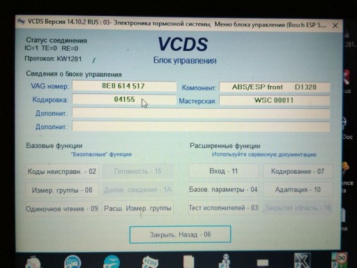
Подключаем диагностический прибор VAG-COM к автомобилю и заходим в блок 03 — Электроника тормозной системы.
Жмём кнопку Коды неисправностей — 02:
- Адрес 03: Электроника тормозной системы Label: 8E0-614-517.lbl
Номер блока управления: 8E0 614 517
Компонент и/или версия: ABS/ESP front D1320
Кодировка: 04155
Код мастерской: WSC 00011
VCID: 65C629BBFF726109FD9-5072 - 3 Найдены неисправности:
- 01206 — Сигнал интервала зажиг. выкл.
27-00 — Недостоверный сигнал - 00778 — Датчик угла поворота рулевого колеса (G85)
37-10 — Неиспр. — Непостоянно - 01826 — Датчик угла поворота рулевого колеса-G85, напр.питания на кл.30
35-00 — —
О чём говорят эти ошибки (возможные причины, устранение), можно посмотреть на сайте wiki.ross-tech.com, что и было сделано:
- 00778 — Steering Angle Sensor (G85)
37-10 — Faulty — Intermittent - Возможные причины:
Неисправен датчик угла поворота рулевого колеса G85 - http://wiki.ross-tech.com/wiki/index.php/00778
- 01826 — Sensor for Steering Angle (G85); Supply Voltage Terminal 30
35-00 — — - Возможные причины:
Временное прерывание напряжения питания
Неисправен датчик угла поворота рулевого колеса G85
Неисправен модуль управления рулевой колонки J527 - При обнаружении в Audi A4 / S4 / RS4 / Cabriolet (8E / 8H): Если «Базовая установка» (адаптация датчика) не работает или ошибка снова возникает после очистки.
- Примечание:
2001: Модуль рулевой колонки J527 был наиболее распространенной причиной возникновения ошибки
2002: Датчик углового положения G85 был наиболее распространенной причиной возникновения ошибки
2003/2004: Опыт показал, что датчик угла рулевого управления G85 был единственной причиной возникновения ошибки
2006/2007: Контрольный модуль рулевой колонки J527 был наиболее распространенной причиной возникновения ошибки - http://wiki.ross-tech.com/wiki/index.php/01826
Сразу обратили внимание на примечания ко второй ошибке. На всякий случай )) попробовали сделать адатпацию датчика G85 — не прошла. Стало понятно, что без ELSA (Electronic Service Information System) проблему не решить.
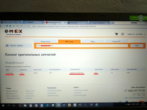
По VIN узнали необходимые нам данные автомобиля:
- Автомобиль: Audi A4 (8E) 1.9TDi
- Дата выпуска: 13.03.2001
- Двигатель: AWX
- Трансмиссия: FEC
И используя эти данные, зашли в раздел Руководство по ремонту, программы ELSA.
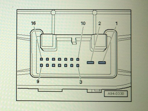
Подробно о датчике угла поворота рулевого колеса G85 и блоке управления рулевой колонки J527
Если заглянуть в электрические схемы…
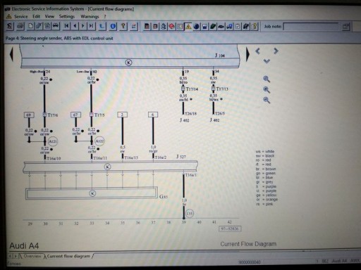
… то видно, что контакты датчика угла поворота руля G85 заходят в блок управления рулевой колонки J527 и уже из него, по цифровой шине CAN (оранжево-чёрный — High и оранжево-коричневый — Low), сигнал идёт в блок управления тормозной системы ABS — J104. Не особо веря, что неисправен сам датчик G85, поскольку ломаться там особо нечему, решили проверить блок J527.
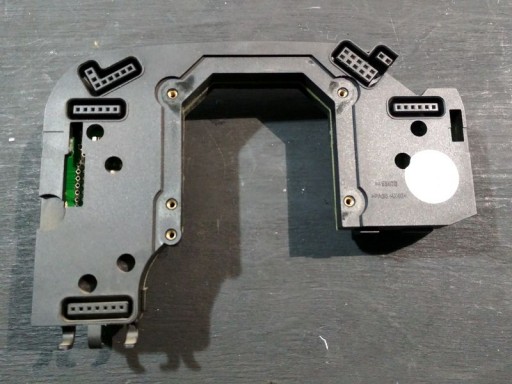
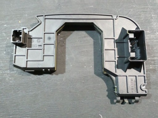
Блок управления рулевой колонки J527
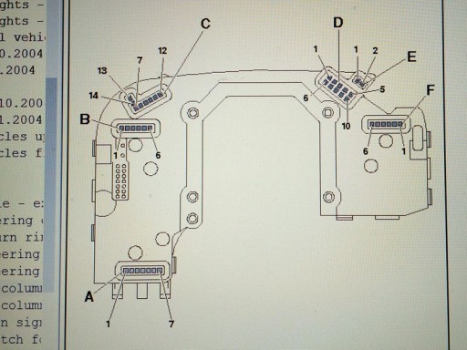
Разъём A — Connector for cruise control system:
- 1 — Earth
- 2 — Fix
- 3 — Distance
- 4 — 12V voltage supply
- 5 — Activation/touch function «Off»
- 6 — Locked «Off»
Разъём B — Connector for turn signal:
- 1 — Earth
- 2 — Radio telephone (special-purpose vehicles)
- 3 — Alarm (special-purpose vehicles)
- 4 — Vacant
- 5 — Headlight flasher/light control
- 6 — Turn signal indicators
Разъём C — Connector for multi-function steering wheel / Tiptronic / Heated steering wheel
- 7 — Tiptronic «-«
- 8 — Multi-function steering wheel «+» voltage supply
- 9 — Multi-function steering wheel data
- 10 — Tiptronic «+»
- 11 — Multi-function steering wheel dimmer
- 12 — Tiptronic earth
- 13 — Heated steering wheel «+»
- 14 — Heated steering wheel «-«
Разъём D — Steering angle sensor
- 1 — Light barrier 5
- 2 — Light barrier 3
- 3 — Light barrier 1
- 4 — 12V vitage supply
- 5 — 5V voltage supply
- 6 — Light barrier 6
- 7 — Light barrier 4
- 8 — Light barrier 2
- 9 — Steering angle sensor earth
- 10 — Light barrier 7
Разъём E — Horn
- 1 — Horn earth
- 2 — Horn
Разъём F — Wiper system
- 1 — Earth
- 2 — Intermittent wipe potentiometer
- 3 — On-board computer
- 4 — Vacant
- 5 — Wash
- 6 — Wipe
Разъём с обратной стороны — Multi-pin connector
- 1 — Earth
- 2 — Terminal 30
- 3 — CAN drive Bus screen
- 4 — Vacant
- 5 — Cruise control locked Off
- 6 — Alarm (special-purpose vehicles)
- 7 — Radio telephone (special-purpose vehicles)
- 8 — Data Bus Low (convenience)
- 9 — Data Bus High (convenience)
- 10 — Data drive Bus (screened) High
- 11 — Data drive Bus (screened) Low
- 12 — Ignition lock terminal 75
- 13 — Ignition lock terminal 15
- 14 — Ignition lock S contact
- 15 — Ignition lock terminal 50
- 16 — Ignition lock terminal P
Измерили и «прозвонили» здесь всё что было можно и нужно — в пределах нормы. Единственное отклонение, Разъём D — pin 4, не было +12В. Но как выяснилось, этого питания не было, потому что блок рулевой колонки «видел» неисправность датчика и не подавал питание. То есть получается, что первична ошибка 00788, а как следствие, появляется 01826.
Датчик угла поворота руля G85

Датчик угла поворота рулевого колеса является частью подрулевого шлейфа.
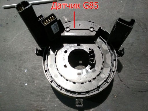
Чтобы его снять, нужно разобрать пластиковый кожух рулевой колонки. Установить колёса в направлении прямолинейного движения и снять руль. После чего можно будет добраться и до шлейфа, с датчиком.
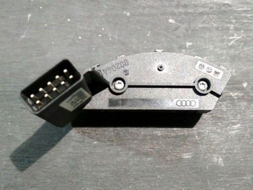
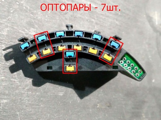
Так выглядит датчик угла поворота рулевого колеса. Семь оптопар и ещё кое-какие элементы на плате. На первый взгляд кажется, что ломаться здесь особо нечему…
… Приглядеться к этому поломанному устройству повнимательнее, нам захотелось после того, как мы узнали его цену в магазине.
Стоимость его составляет около 20-ти тысячь рублей! Конечно можно попытаться купить на авторазборе, но тут как повезёт. Наш, неисправный датчик, был именно оттуда.
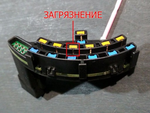
Итак, после тщательного осмотра, простимулированного ценой датчика G85, была найдена причина ошибок 00778 и 01826 — грязь, забившаясь между светопередатчиком и фотоприёмником. Чистим, ставим на место и обучаем.
На всякий случай, вот оригинал и наш перевод, процедуры обучения датчика угла поворота рулевого колеса.
Оригинал:
Steering Angle Sensor (G85) Calibration
- Before starting the procedure turn the steering wheel at least 30 ° left and back straight ahead.
- [Meas. Blocks — 08]
Group 005 Field 1 (Steering Angle Sensor -G85-)
Specification: 0.0 °
Tolerance (when straight): ±5.0 °
[Done, Go Back]
[Login — 11]
Enter 40168
[Do It!]
[Basic Settings — 04]
Group 001
[Go!]
[Done, Go Back]
[Fault Codes — 02]
All fault codes should have disappeared.
[Done, Go Back] - Special Notes
Some of the Bosch 5.7 modules will not show live Steering Angle Sensor (G85) readings after the Login and Coding are performed. If this is the case -2.5 ° may be stuck in Measuring Block 005 and will not change when the wheel is turned. Make the wheels as straight as possible and continue with the Steering Angle Sensor (G85) Calibration. After doing the G85 Calibration, you may get a 01486 — System Function Test Active, this is normal. Please see 01486.
Свободный перевод:
Калибровка датчика угла поворота руля G85
- Перед началом процедуры поверните рулевое колесо на 30 градусов влево и вправо, от прямолинейного движения и установите руль прямо.
- Нажимаем кнопку [Вход — 11]
Вводим 40168
Нажимаем [Ввод]
Выбираем [Базов. параметры — 04]
Затем [Группа 001]
Нажимаем [Чтение]
И кнопку [Готово]
Заходим в [Коды неисправностей — 02] - Все коды неисправностей должны исчезнуть.
- Примечание:
После выполнения калибровки G85, может возникнуть неисправность 01486 — Тест системных функций активен, это нормально. Покатайтесь во дворе кругами и восьмёрками, ошибка уйдёт и индикатор неисправности погаснет.
Записаться на ремонт и задать вопросы по данному материалу, вы можете на странице Контакты.
Ремонт
-
#7
Las fotos son para saber que tipo de sensores lleva , barrera , reflexivos , vista de rayos X , etc !
Fogonazo
«Qualified exorcist approved by the Vatican»
-
#9
Estos son los 4 sensores de arriba. Abajo hay otro igual. En la otra imágen está el sensor. . .
Y ¿ Que tal unas imágenes donde se pueda llegar a ver algo ?
-
#11
Puede que sean sensores capacitivos, sería interesante que quites esa placa y tome una foro en la que se pueda ver bien lo que tiene por el otro lado
MCS son las siglas de Movile Control System SA
Última edición: Oct 12, 2018