
|
kodak dryveiw 5800 |
||||||
|
||||||
|
||||||
|
||||||
|
||||||
|
||||||
|
||||||
|
||||||
|
||||||
|
||||||
|
||||||
|
||||||
|
||||||
|
||||||
|
||||||
|
||||||
|
||||||
|
||||||
|
||||||
|
||||||
|
||||||
|
||||||
|
||||||
|
||||||
|
||||||
|
||||||
|
||||||
|
||||||
|
||||||
|
||||||
|
||||||
|
||||||
|
||||||
|
||||||
|
||||||
|
||||||
|
||||||
|
||||||
|
||||||
|
||||||
|


Troubleshooting
Code
01004
MIM Core: Internal Software
Error
04200
MIM Core: Disk Full
06400
MIM Core: Image Page Error
06410
MIM Core: Image Rendering
Error
06411
MIM Core: Image Data Error
06420
MIM Core: Internal Software
Error
06430
MIM Core: Internal Software
Error
10001
MIS: Internal Software Error
3-6
Condition codes are shown on the display screen in the order in which they
are generated. If there is more than one code associated with the current
condition of the imager, the first code is shown on the display screen for six
seconds, while other codes in the list are displayed for three seconds as the
list is cycled. The LEDs on the left side of the local panel will be on
whenever there is a condition code of that type.
Table 3-5: Condition Codes
Web Portal Message
User Action
1. Shut down the imager, then start the imager.
2. If the error persists, call for service.
1. Delete jobs in the «Unprintable jobs» queue.
2. Load requested film type for jobs in the «Waiting
for media» queue.
3. If the error persists, call for service.
1. Delete jobs in the «Unprintable jobs» queue.
2. Resend the print job from the image source.
3. If the error persists, call for service.
1. Delete jobs in the «Unprintable jobs» queue.
2. Resend the print job from the image source.
3. If the error persists, call for service.
1. Delete jobs in the «Unprintable jobs» queue.
2. Resend the print job from the image source.
3. If the error persists, call for service.
1. Delete jobs in the «Unprintable jobs» queue.
2. Resend the print job from the image source.
3. If the error persists, call for service.
1. Delete jobs in the «Unprintable jobs» queue.
2. Resend the print job from the image source.
3. If the error persists, call for service.
1. Shut down the imager, then start the imager.
2. If the error persists, call for service.
2G0733
2011-09-09
-
Contents
-
Table of Contents
-
Troubleshooting
-
Bookmarks
Quick Links
KODAK DRYVIEW 5800 Laser Imager
CARESTREAM DRYVIEW 5850 Laser Imager
User’s Guide
Related Manuals for Kodak Dryview 5800
Summary of Contents for Kodak Dryview 5800
-
Page 1
KODAK DRYVIEW 5800 Laser Imager CARESTREAM DRYVIEW 5850 Laser Imager User’s Guide… -
Page 3: Table Of Contents
DRYVIEW 5800 and 5850 Laser Imagers — — — — — — — — — — — — — — — — — — — — — — — — — — — — — — — — — -…
-
Page 4
Table of Contents Clearing Film Jams — — — — — — — — — — — — — — — — — — — — — — — — — — — — — — — — — — — — — — — — — — — — — — — — — — — — — — — — 3-13 Film Jam — Code 2x-116 — — — — — — — — — — — — — — — — — — — — — — — — — — — — — — — — — — — — — — — — — — — — — — — — — — 3-14 Film Jam — Code 2×126 — — — — — — — — — — — — — — — — — — — — — — — — — — — — — — — — — — — — — — — — — — — — — — — — — — — 3-17 Film Jam — Code 26325 — — — — — — — — — — — — — — — — — — — — — — — — — — — — — — — — — — — — — — — — — — — — — — — — — — — 3-19… -
Page 5: Overview
Chapter 5 of this manual. Intended Use The KODAK DRYVIEW 5800 Laser Imager provides high quality hard copy film output from digital imaging source modalities for use in medical imaging diagnosis and referral. Electronic image information signals are managed and transformed optically to expose KODAK DRYVIEW media.
-
Page 6: How The Laser Imager Works
Overview How the Laser Imager Works The imager is a network printer connected on a network along with one or more medical imaging devices. It prints images sent over the network from medical imaging devices or workstations sending images concurrently. Modality Network Modality…
-
Page 7: System Components
Overview System Components Film trays. Your imager is configured with two film trays. Each film tray holds a different size of film. Both film trays must be installed in order for the imager to operate. Film feed transport. The film feed transport orients and centers the film while moving the film from the film tray to the imaging portion of the imager.
-
Page 8: Print Sequence
Overview Print Sequence When the imager receives a print request, it determines the requested film size and type and then it selects the appropriate film tray. Each time the imager receives a print request, the following print sequence occurs: 1. Suction cups in the pickup area lift a single sheet of film out of the tray and feed the film into the transport rollers.
-
Page 9: Automatic Image Quality Control
Overview Automatic Image Quality Control An internal densitometer is a key element in the Automatic Image Quality Control (AIQC) process. The densitometer enables the imager to automatically adjust image processing parameters to produce the best image. The imager adjusts these parameters each time it prints a calibration film. A calibration film is printed when: •…
-
Page 11: Using And Maintaining The Imager
Using and Maintaining the Imager Operator Control of the Imager During normal operation, the imager receives and automatically prints images sent by modalities over a network. Very little operator control is required. The main responsibilities of the operator are described in the following section, along with overview information about using the imager.
-
Page 12: Local Panel And Display Screen
Using and Maintaining the Imager Local Panel and Display Screen Local Panel / Display Screen Ready LED. When steady on, the LED indicates that the imager is ready for printing. When flashing, the imager is processing and printing films. When unlit, the imager is not ready to print.
-
Page 13: Display Screen Icons
Using and Maintaining the Imager Display Screen Icons Icon Description This icon indicates that film calibration is required. The imager is unable to print jobs from this tray until a successful calibration occurs. This icon indicates that a door is open on the imager. This icon indicates an error with the film tray.
-
Page 14
Using and Maintaining the Imager Icon Description Icons in Menu Selection Mode The following icons appear on the display screen when you are in Menu Selection Mode. These icons represent the changed functionality of the buttons on the right side of the local panel. While in Menu Selection Mode, press the button (6 in the graphic on page 2-2) to display the Test Print or Maintenance Reset screen. -
Page 15: Web Portal
Using and Maintaining the Imager Web Portal The Web Portal is your interface to additional functions on the imager. In the Web Portal, you can view and manage the imager’s connections over the network, configure features, and view and correct error messages and general status.
-
Page 16: Accessing The Web Portal
Using and Maintaining the Imager Accessing the Web To access the Web Portal, you will need a desktop or laptop computer that is Portal connected to the network. 1. On a desktop or laptop computer, start MICROSOFT INTERNET EXPLORER. 2. In the address field, type: http://<IP address> NOTE: <IP address>…
-
Page 17: Operations
Using and Maintaining the Imager Operations Unloading and IMPORTANT: Leave the imager powered on while loading or unloading loading the Film Tray the film tray. When 100 sheets of film have been used, a 0 film count appears on the display screen.
-
Page 18
Using and Maintaining the Imager Bag holder Film package Diverter 4. Pull the diverter (plastic bar) and bag holder (silver bar) into the up position. 5. Press the new film package down in the tray with the label facing up. 6. -
Page 19
Using and Maintaining the Imager Tear strip 10. Remove the tear strip from the plastic bag. 11. Swing the diverter of the film tray back in place. IMPORTANT: Do not install the film saver onto the film tray. 12. Slide the tray back into the imager slot. Plastic bag 13. -
Page 20: Inserting The Film Saver And Removing The Film Tray
Using and Maintaining the Imager Inserting the Film A film saver must be inserted into a film tray before: Saver and Removing • The hood is opened. the Film Tray • Any panel on the imager is removed. • Film tray with film in it is removed. 1.
-
Page 21: Calibration Prints
Using and Maintaining the Imager Calibration Prints imager calibration is performed by printing a calibration print. A calibration print has a step wedge pattern with a series of 26 stripes of increasing optical density. The only purpose of a calibration print is to calibrate the imager.
-
Page 22: Working With Quality Test Prints
Using and Maintaining the Imager Working with Quality The imager can print an internally generated density test print with a Test Prints SMPTE pattern. Density test prints can be used as a quality assurance tool to verify the uniformity of films printed by the imager. The 5850 Laser Imager provides additional test images that can be used for mammography quality control.
-
Page 23: Operator Maintenance
Using and Maintaining the Imager Operator Maintenance Changing the Charcoal Filter CAUTION In the U.S., exhausted charcoal filters are considered to be non-hazardous waste according to the U.S. Environmental Protection Agency Resource Conservation Recovery Act (RCRA). Municipality owned and licensed solid waste management facilities are an appropriate disposal option.
-
Page 24
Using and Maintaining the Imager 3. Raise the hood. 4. Pull the front panel forward. 5. Remove the charcoal filter by lifting it up and pulling it forward. 6. Install a new charcoal filter. 7. Close the front panel. 8. Close the hood. 9. -
Page 25: Troubleshooting
Troubleshooting Error and Alarm Indications The imager can detect errors and other conditions that require operator action. These errors or abnormal conditions are reported on the display screen and on the Web Portal in the form of condition codes and messages.
-
Page 26: Printer Status Messages
Troubleshooting Printer Status Messages The following table describes how the local panel and Web Portal indicate printer status to the user. Table 3-2: Printer Status Messages Printer Web Portal Local Panel DICOM Status Description Status Display Any Film • Ready LED off Not Ready WARNING / At least one of the film…
-
Page 27: Film Tray Status Messages
Troubleshooting Table 3-2: Printer Status Messages (Continued) Printer Web Portal Local Panel DICOM Status Description Status Display Warming • Ready LED off Warming=xx WARNING / The Processor is warming • Warming LED on PROC INIT up and will not be ready to •…
-
Page 28
Troubleshooting Table 3-3: Film Tray Status Messages (Continued) Film Tray Web Portal Local Panel Description State Display Manual Mode • Attention LED on The film in this film tray does • Status code: 21002 (upper), not meet AIQC standards. 23002 (lower) However, the user has selected •… -
Page 29: Job Manager Status Messages
Troubleshooting Job Manager Status Messages The following table describes how the local panel and Web Portal indicate job status to the user. Table 3-4: Job Manager Status Messages Job Manager Web Portal Display Screen Description Status Display Active Shows how many The imager is accepting DICOM job jobs having this requests and film is available for all current…
-
Page 30: Condition Codes
Troubleshooting Condition Codes Condition codes are shown on the display screen in the order in which they are generated. If there is more than one code associated with the current condition of the imager, the first code is shown on the display screen for six seconds, while other codes in the list are displayed for three seconds as the list is cycled.
-
Page 31
Troubleshooting Table 3-5: Condition Codes (Continued) Code Web Portal Message User Action 10003 MIS: Image Buffer Error 1. Shut down the imager, then start the imager. 2. If the error persists, call for service. 10015 MIS: Database Error 1. Shut down the imager, then start the imager. 2. -
Page 32
Troubleshooting Table 3-5: Condition Codes (Continued) Code Web Portal Message User Action 20703 none 1. Press and hold the Menu Selection button for five seconds. 2. Press and release the Menu Selection button again to display the Error Reset menu. Delete the jobs in the Unprintable Jobs Queue. -
Page 33
Troubleshooting Table 3-5: Condition Codes (Continued) Code Web Portal Message User Action 21119 or xxxxx Supply: Internal 1. Cover the film tray with the film saver. Remove the 23119 Hardware Failure tray from the imager. 2. Re-insert the film tray and remove the film saver. 3. -
Page 34
Troubleshooting Table 3-5: Condition Codes (Continued) Code Web Portal Message User Action 21146 or xxxxx Supply: Unsupported 1. The imager has not been configured to use this film 23146 Film Size size. 2. Try a different film size or reconfigure the imager. 3. -
Page 35
Troubleshooting Table 3-5: Condition Codes (Continued) Code Web Portal Message User Action 27123 Optics: Internal Hardware 1. Shut down the imager, then start the imager. Failure 2. If the error persists, call for service. 27601 Optics: Calibration Failed 1. Shut down the imager, then start the imager. 2. -
Page 36
Troubleshooting Table 3-5: Condition Codes (Continued) Code Web Portal Message User Action 28931 Processor: Internal 1. Shut down the imager, then start the imager. Communications Failure 2. If the error persists, call for service. 29154 Densitometer: Internal 1. Shut down the imager, then start the imager. Communications Failure 2. -
Page 37: Clearing Film Jams
Troubleshooting Clearing Film Jams CAUTION Shutting off power to clear a film jam is not required. Jam Areas and Film Path 2011-09-09 2G0733 3-13…
-
Page 38: Film Jam — Code 2X-116
Troubleshooting Film Jam — Code 1. Remove the film trays (see “Inserting the Film Saver and Removing 2x-116 the Film Tray”). Film tray slots 2. Remove any misplaced films from Area 1. This area can be accessed through the film trays slots. NOTE: If the film is not accessible from the front of the imager, continue with…
-
Page 39
Troubleshooting Hood Left panel 2 thumb screws 3. Open the hood. 4. Loosen the 2 thumb screws and remove the left panel. 2011-09-09 2G0733 3-15… -
Page 40
Troubleshooting Pickup access areas 5. Remove any misplaced films seen in the pickup access areas. 6. If Area 1 did not contain misplaced films, take the film trays to a dark room and remove the film saver. Remove any misplaced films and cover the tray with the film saver. -
Page 41: Film Jam — Code 2X126
Troubleshooting Film Jam — Code 1. Remove the film trays (see “Inserting the Film Saver and Removing 2×126 the Film Tray”). Film tray slots 2. Remove any misplaced films from Area 1. This area can be accessed through the film trays slots. 3.
-
Page 42
Troubleshooting Hood Left panel 2 thumb screws 5. Open the hood. 6. Loosen the 2 thumb screws and remove the left panel. Pickup access areas 3-18 2G0733 2011-09-09… -
Page 43: Film Jam — Code 26325
Troubleshooting 7. Remove any misplaced films seen in the pickup access areas. 8. Set the left panel in place and tighten the 2 thumb screws. 9. Close the hood. Film Jam — Code IMPORTANT: If this error occurred at the same time as 2x-126, follow the 26325 instructions for “Film Jam — Code…
-
Page 44
Troubleshooting 4. Carefully remove any films found in the drum area. 5. Close the drum cover and secure the cover latches. If the film was not found in the drum area, continue with Step Hood Left panel 2 thumb screws 6. -
Page 45: Film Jam — Code 26544
Troubleshooting Film advance knob 8. Use the manual advance knob to move the film through the processor. 9. Set the left panel in place and tighten the 2 thumb screws. 10. Close the hood. If film was not previously removed, the misplaced films will emerge from the imager within two minutes.
-
Page 46: Calling For Support
Troubleshooting Calling for Support If you cannot correct a condition and need help, call for support. Have the following information ready when you call: • Model Number • Serial Number or K-Number • Condition code and message if they are shown on the display screen and Web Portal 3-22 2G0733…
-
Page 47: Film Technical Information
Film Technical Information General Description This section describes the characteristics of laser imaging film, not the operation of the laser imager. The laser imaging film is a high-resolution, infrared-sensitive, photothermographic film designed specifically for the laser imager. The laser imaging film is packaged in daylight-load packages and is available in blue, clear, and mammography film types.
-
Page 48: Environmental Impact
Film Technical Information Environmental Tests show that the laser imaging film is not considered hazardous to the Impact environment. As a result, you can develop, recycle, and dispose of film with less impact on the environment than if you were using wet-developed silver halide films.
-
Page 49: Archiving Developed Film
Film Technical Information lighting. This is virtually undetectable and has no effect on image quality (typically 0.02 change in density). This small density increase is uniform and permanent upon full exposure of the film under normal handling conditions (room light or view box). Archiving Developed The laser imaging film has been tested and can be archived for more than Film…
-
Page 51: Specifications
Specifications Location Equipment Specifications Unpacked Packed Height 62 cm (24 in.) 95 cm (37 in.) Width 62 cm (24 in.) 81 cm (32 in.) Depth 66 cm (26 in.) without film trays 106 cm (42 in.) 76 cm (30 in.) with film trays Weight 70 kg (155 lb) 147.4 kg (325.0 lb)
-
Page 52: Other Location Considerations
Specifications Other Location Additional factors that influence where the imager is located include Considerations proximity to patients, flammable materials, liquids, and other equipment. CAUTION This equipment is not contained in a sealed cabinet. Do not use this equipment in locations where it can come in contact with liquids, including body fluids.
-
Page 53: Environmental Requirements
Specifications Environmental Requirements Temperature • Operating: 15–33 °C (59–91 °F) • Storage: From –40 through 60 °C (From –40 through 140 °F) Relative Humidity • Operating: 20–80 % RH, noncondensing • Storage: 10–90 % RH, noncondensing Altitude 30 m (100 ft) below sea level to 2438 m (8000 ft) above sea level Surface Condition The surface must be a level (must be level within 1 °) table top or counter capable of supporting the weight of the imager.
-
Page 54: Power Requirements
KODAK DRYVIEW DVB+ Laser Imaging Film • KODAK DRYVIEW DVB+ Premium Laser Imaging Film • 5850 Laser Imager only: KODAK DRYVIEW Mammography Laser Imaging Film and KODAK DRYVIEW DVM+ Mammography Laser Imaging Film NOTE: Not all film types are available in every country. 2G0733…
-
Page 55: Film Sizes
Specifications Film Sizes The imager accommodates the following film sizes: • 20 x 25 cm (8 x 10 in.) • 25 x 30 cm (10 x 12 in.) • 28 x 35 cm (11 x 14 in.) • 35 x 35 cm (14 x 14 in.) •…
-
Page 57: Glossary
Glossary Computed Radiography, the process of creating digital radiographic images. Computed Tomography, the process of creating digital tomographic images. Cycle power Cycle power means to shut down and power up the Laser Imager. DICOM Digital Imaging and Communications in Medicine. A TCP/IP-based protocol for transmitting and receiving medical imaging and related data over a network.
-
Page 58
Glossary Test type The type of test film that will be printed. Two film test types are available: a density test film (SMPTE pattern) and a calibration film. Transfer Function Tables. Unprintable queue The queue of jobs that cannot be printed because of problems with the job description. -
Page 59
Index Agency compliance, 1-5 Job manager status messages, 3-5 Altitude, 5-3 Automatic image quality control (AIQC), 1-5 Laser specifications, 5-3 Local panel layout, 2-2 Calling for support, 3-22 Conventions, 1-5 Correcting film jams, 3-13 MCS printer status messages, 3-2 Messages DICOM printer status, 3-1 DICOM, 1-1 Film supply status, 3-3… -
Page 61
Publication History Revision Date Reason for Change 2008-01-14 First release 2009-02-27 Incorporated details for 5850 Laser Imager. 2009-05-06 Updated the Intended Use statement for the 5850 Laser Imager 2011-09-09 Modified formatting of dates and measurements (EN 1041) -
Page 62
Carestream Health, Inc. 150 Verona Street Rochester, NY 14608 © Carestream Health, Inc., 2011 CARESTREAM and DRYVIEW are trademarks of Carestream Health, Inc. The Kodak trademark and trade dress are used under license from Kodak. Pub No. 2G0733 Rev. D…
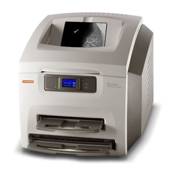
Service manual for the Kodak 5800 Dryview film printer. The Dryview 5800 is a medical film printer capable of DICOM connections over a network.This manual covers detailed installation and maintenance as well as error code descriptions.
-
Carestream Health, 2008
Publication No. 2G094731JAN08
SERVICE MANUAL
for the
Kodak DryView 5800 LASER IMAGER
Service Code: 1115
IMPORTANT: Qualified service personnel must install and repair
this equipment. When doing the procedures in this document, you
must use safe work practices and wear the correct PersonalProtective Equipment (i.e., SAFETY EYEWEAR) according to your
Companys Standard Operating Procedures.Downloaded from www.Manualslib.com manuals search engine
-
PLEASE NOTE The information contained herein is based on the
experience and knowledge relating to the subject matter gained by
Carestream Health, Inc. prior to publication.No patent license is
granted by this information.Carestream Health, Inc. reserves the
right to change this information without notice, and makes no
warranty, express or implied, with respect to this information.
Carestream Health, Inc. shall not be liable for any loss or damage,
including consequential or special damages, resulting from any use
of this information, even if loss or damage is caused by Carestream
Health, Inc.s negligence or other fault.Downloaded from www.Manualslib.com manuals search engine
-
2G0947 — 31JAN08 iii
Table of ContentsSafety Information — — — — — — — — — — — — — —
— — — — — — — — — — — — — — — — — — — — — — — — — — — — — — — — — —
— — — — — — — — — — 1-1Installation Instructions — — — — — — — — — — — — — — — — — — —
— — — — — — — — — — — — — — — — — — — — — — — — — — — — — — — — — —
— 2-1Packing List — — — — — — — — — — — — — — — — — — — — — — — — —
— — — — — — — — — — — — — — — — — — — — — — — — — — — — — — — — — —
— — 2-1Necessary Materials — — — — — — — — — — — — — — — — — — — —
— — — — — — — — — — — — — — — — — — — — — — — — — — — — — — — — — —
— 2-1Connecting the LAPTOP COMPUTER to the IMAGER — — — — — — — — —
— — — — — — — — — — — — — — — — — — — — — — 2-2Energizing the
IMAGER — — — — — — — — — — — — — — — — — — — — — — — — — — — — — —
— — — — — — — — — — — — — — — — — — — — — — 2-3De-energizing the
IMAGER — — — — — — — — — — — — — — — — — — — — — — — — — — — — — —
— — — — — — — — — — — — — — — — — — — — 2-3Logging Onto the SERVICE
TOOL — — — — — — — — — — — — — — — — — — — — — — — — — — — — — — —
— — — — — — — — — — — — — — 2-4Logging Off the SERVICE TOOL — — — —
— — — — — — — — — — — — — — — — — — — — — — — — — — — — — — — — — —
— — — — — — — — 2-4Doing the Mechanical Setup — — — — — — — — — — —
— — — — — — — — — — — — — — — — — — — — — — — — — — — — — — — — — —
— — — — — 2-5Completing the Uncrating — — — — — — — — — — — — — — — — — — — —
— — — — — — — — — — — — — — — — — — — — — — — — — — — — —
2-5Checking the Accessories — — — — — — — — — — — — — — — — — — — —
— — — — — — — — — — — — — — — — — — — — — — — — — — — — — 2-6Moving
the IMAGER — — — — — — — — — — — — — — — — — — — — — — — — — — — —
— — — — — — — — — — — — — — — — — — — — — — — — 2-7Removing the
SHIPPING RESTRAINTS and Packing Material — — — — — — — — — — — — —
— — — — — — — — — — 2-7Doing the Configuration — — — — — — — — — — — — — — — — — — — —
— — — — — — — — — — — — — — — — — — — — — — — — — — — — — — — —
2-13Setting the Language — — — — — — — — — — — — — — — — — — — — —
— — — — — — — — — — — — — — — — — — — — — — — — — — — — — — —
2-13Checking the Values for the DICOM Source Communications — — — —
— — — — — — — — — — — — — — — — — — — 2-13Setting the IMAGER to be
a Destination — — — — — — — — — — — — — — — — — — — — — — — — — — —
— — — — — — — — — — — 2-14Setting the System Clock — — — — — — — —
— — — — — — — — — — — — — — — — — — — — — — — — — — — — — — — — — —
— — — — — — — 2-16Setting the Host Name and the IP Address — — — —
— — — — — — — — — — — — — — — — — — — — — — — — — — — — — — — — —
2-19Setting up Service Tracking — — — — — — — — — — — — — — — — — —
— — — — — — — — — — — — — — — — — — — — — — — — — — — — —
2-20Loading Customer Film — — — — — — — — — — — — — — — — — — — — —
— — — — — — — — — — — — — — — — — — — — — — — — — — — — —
2-21Checking the Installed Hardware and Film Type — — — — — — — — —
— — — — — — — — — — — — — — — — — — — — — — — — 2-21Doing the SCP
Services Configuration — — — — — — — — — — — — — — — — — — — — — —
— — — — — — — — — — — — — — — — — — 2-22Checking Image Quality — —
— — — — — — — — — — — — — — — — — — — — — — — — — — — — — — — — — —
— — — — — — — — — — — — — 2-23Editing the Service History Log — — —
— — — — — — — — — — — — — — — — — — — — — — — — — — — — — — — — — —
— — — — — — — 2-26Configuring the CARESTREAM REMOTE MANAGEMENT
SERVICES — — — — — — — — — — — — — — 2-27Backing Up the System
Configuration — — — — — — — — — — — — — — — — — — — — — — — — — — —
— — — — — — — — — — — — — 2-31Instructing the Operator — — — — — —
— — — — — — — — — — — — — — — — — — — — — — — — — — — — — — — — — —
— — — — — — — — — — 2-32Using the Default Passcode — — — — — — — —
— — — — — — — — — — — — — — — — — — — — — — — — — — — — — — — — — —
— — — — — 2-32Adjustments and Replacements — — — — — — — — — — — — — — — — — —
— — — — — — — — — — — — — — — — — — — — — — — — — — — — — — —
3-1Adjustments — — — — — — — — — — — — — — — — — — — — — — — — — —
— — — — — — — — — — — — — — — — — — — — — — — — — — — — — — — — — —
— 3-1PROCESSOR — DRUM Temperature — — — — — — — — — — — — — — — — — —
— — — — — — — — — — — — — — — — — — — — — — — — 3-1IMAGING AY —
Alignment — — — — — — — — — — — — — — — — — — — — — — — — — — — — —
— — — — — — — — — — — — — — — — — — — 3-5IMAGING AY — Start Index
Delay, Start of Scan — — — — — — — — — — — — — — — — — — — — — — —
— — — — — — — — — — 3-7IMAGING AY — Page Start Delay, Start of Page
— — — — — — — — — — — — — — — — — — — — — — — — — — — — — — — — — —
3-9Replacements — — — — — — — — — — — — — — — — — — — — — — — — — —
— — — — — — — — — — — — — — — — — — — — — — — — — — — — — — — — —
3-12LEFT PANEL — — — — — — — — — — — — — — — — — — — — — — — — — —
— — — — — — — — — — — — — — — — — — — — — — — — — — — — — —
3-12RIGHT PANEL — — — — — — — — — — — — — — — — — — — — — — — — — —
— — — — — — — — — — — — — — — — — — — — — — — — — — — — — 3-13BACK
PANEL — — — — — — — — — — — — — — — — — — — — — — — — — — — — — — —
— — — — — — — — — — — — — — — — — — — — — — — — 3-14TOP COVER — — —
— — — — — — — — — — — — — — — — — — — — — — — — — — — — — — — — — —
— — — — — — — — — — — — — — — — — — — — 3-15FRONT PANEL — — — — — —
— — — — — — — — — — — — — — — — — — — — — — — — — — — — — — — — — —
— — — — — — — — — — — — — — — 3-17LOCAL PANEL AY — — — — — — — — —
— — — — — — — — — — — — — — — — — — — — — — — — — — — — — — — — — —
— — — — — — — — — 3-18SWITCH, INTERLOCK — LEFT and RIGHT PANELS — —
— — — — — — — — — — — — — — — — — — — — — — — — — — 3-19SWITCH,
INTERLOCK — TOP COVER — — — — — — — — — — — — — — — — — — — — — — —
— — — — — — — — — — — — — — — 3-21SWITCH, SERVICE — — — — — — — — —
— — — — — — — — — — — — — — — — — — — — — — — — — — — — — — — — — —
— — — — — — — — — 3-22PROCESSOR AY — — — — — — — — — — — — — — — —
— — — — — — — — — — — — — — — — — — — — — — — — — — — — — — — — — —
— — — 3-23PROCESSOR DRUM — — — — — — — — — — — — — — — — — — — — —
— — — — — — — — — — — — — — — — — — — — — — — — — — — — — —
3-27Downloaded from www.Manualslib.com manuals search engine
-
iv 2G0947 — 31JAN08
PROCESSOR COVER — — — — — — — — — — — — — — — — — — — — — — — —
— — — — — — — — — — — — — — — — — — — — — — — — — — -3-29BELT, DRUM
DRIVE — — — — — — — — — — — — — — — — — — — — — — — — — — — — — — —
— — — — — — — — — — — — — — — — — — — -3-30MOTOR, DRUM DRIVE (M8) —
— — — — — — — — — — — — — — — — — — — — — — — — — — — — — — — — — —
— — — — — — — — — -3-31FAN AY, PROCESSOR — — — — — — — — — — — — —
— — — — — — — — — — — — — — — — — — — — — — — — — — — — — — — — — —
— — -3-32FILM DIVERTER AY and FELT PAD AY — — — — — — — — — — — — —
— — — — — — — — — — — — — — — — — — — — — — — -3-33PROCESSOR GASKET
— — — — — — — — — — — — — — — — — — — — — — — — — — — — — — — — — —
— — — — — — — — — — — — — — — -3-35PROCESSOR ROLLERS — — — — — — —
— — — — — — — — — — — — — — — — — — — — — — — — — — — — — — — — — —
— — — — — — — -3-37DENSITOMETER AY — — — — — — — — — — — — — — — —
— — — — — — — — — — — — — — — — — — — — — — — — — — — — — — — — — —
-3-38TURNAROUND DRIVE SHAFT, DRIVE WHEEL and HUBS — — — — — — — — —
— — — — — — — — — — — — — -3-41TURNAROUND IDLER SHAFTS and ROLLERS
— — — — — — — — — — — — — — — — — — — — — — — — — — — — — — —
-3-45MOTOR, TURNAROUND ROLLER DRIVE (M9) — — — — — — — — — — — — —
— — — — — — — — — — — — — — — — — -3-47FILM FEED AY — — — — — — — —
— — — — — — — — — — — — — — — — — — — — — — — — — — — — — — — — — —
— — — — — — — — — — — — -3-48MOTOR, FEED ROLLER NIP OPEN/CLOSE (M1)
— — — — — — — — — — — — — — — — — — — — — — — — — — — — — —
-3-53MOTOR, NIP POSITION DRIVE (M2) — — — — — — — — — — — — — — — —
— — — — — — — — — — — — — — — — — — — — — — -3-54FEED ROLLER NIP
DRIVE BELT — — — — — — — — — — — — — — — — — — — — — — — — — — — —
— — — — — — — — — — — — — -3-55NIP ROLLER SET AY — UPPER — — — — —
— — — — — — — — — — — — — — — — — — — — — — — — — — — — — — — — — —
— — — — -3-57NIP ROLLER SET AY — LOWER — — — — — — — — — — — — — —
— — — — — — — — — — — — — — — — — — — — — — — — — — — — -3-58FILM
SEPARATION FAN AY — UPPER — — — — — — — — — — — — — — — — — — — — —
— — — — — — — — — — — — — — — — -3-60FILM SEPARATION FAN AY — LOWER
— — — — — — — — — — — — — — — — — — — — — — — — — — — — — — — — — —
— — — -3-62FILM SEPARATION FAN FILTER — — — — — — — — — — — — — — —
— — — — — — — — — — — — — — — — — — — — — — — — — — -3-63CAM AY,
CASSETTE REGISTRATION — UPPER (M6U) — — — — — — — — — — — — — — — —
— — — — — — — — — -3-64CAM, AY CASSETTE REGISTRATION — LOWER (M6L)
— — — — — — — — — — — — — — — — — — — — — — — — — -3-65SENSOR, FILM
SAVER DETECT — UPPER (S6U) — — — — — — — — — — — — — — — — — — — —
— — — — — — — — — — -3-66SENSOR, FILM SAVER DETECT — LOWER (S6L) —
— — — — — — — — — — — — — — — — — — — — — — — — — — — — —
-3-70SENSOR, FILM TRAY DETECT — UPPER (S5U) — — — — — — — — — — — —
— — — — — — — — — — — — — — — — — — — -3-71SENSOR, FILM TRAY DETECT
— LOWER (S5L) — — — — — — — — — — — — — — — — — — — — — — — — — — —
— — — — -3-73VACUUM PUMP (M4) — — — — — — — — — — — — — — — — — — —
— — — — — — — — — — — — — — — — — — — — — — — — — — — — — —
-3-74PICKUP AY — UPPER — — — — — — — — — — — — — — — — — — — — — —
— — — — — — — — — — — — — — — — — — — — — — — — — — — — -3-76PICKUP
AY — LOWER — — — — — — — — — — — — — — — — — — — — — — — — — — — —
— — — — — — — — — — — — — — — — — — — — — — -3-77MOTOR, PICKUP
DRIVE — UPPER (M3U) and LOWER (M3L) — — — — — — — — — — — — — — — —
— — — — — -3-78SUCTION CUP — — — — — — — — — — — — — — — — — — — —
— — — — — — — — — — — — — — — — — — — — — — — — — — — — — — — — — —
— -3-79VALVE, SOLENOID — UPPER (M5U) and LOWER (M5L) — — — — — — —
— — — — — — — — — — — — — — — — — — -3-80SENSOR, PICKUP HOME —
UPPER (S1U) and LOWER (S1L) — — — — — — — — — — — — — — — — — — — —
— — -3-81SENSOR, FILM CONTACT — UPPER (S2U) and LOWER (S2L) — — — —
— — — — — — — — — — — — — — — — — -3-82SENSOR, FILM SEPARATED —
UPPER (S3U) and LOWER (S3L) — — — — — — — — — — — — — — — — — — —
-3-83IMAGING AY — — — — — — — — — — — — — — — — — — — — — — — — — —
— — — — — — — — — — — — — — — — — — — — — — — — — — — — — —
-3-84SENSOR, START OF PAGE (SOP, S8) — — — — — — — — — — — — — — —
— — — — — — — — — — — — — — — — — — — — — — — -3-85POWER SUPPLY — —
— — — — — — — — — — — — — — — — — — — — — — — — — — — — — — — — — —
— — — — — — — — — — — — — — — — — -3-87HARD DRIVE — — — — — — — — —
— — — — — — — — — — — — — — — — — — — — — — — — — — — — — — — — — —
— — — — — — — — — — — — — -3-89FILM PATH MICROCONTROLLER BOARD — —
— — — — — — — — — — — — — — — — — — — — — — — — — — — — — — —
-3-91DRE MOTHERBOARD — — — — — — — — — — — — — — — — — — — — — — —
— — — — — — — — — — — — — — — — — — — — — — — — — — -3-92Preventive Maintenance — — — — — — — — — — — — — — — — — — — — —
— — — — — — — — — — — — — — — — — — — — — — — — — — — — — — — — —
4-1Necessary Materials — — — — — — — — — — — — — — — — — — — — — —
— — — — — — — — — — — — — — — — — — — — — — — — — — — — — — — — —
4-1PM Intervals — — — — — — — — — — — — — — — — — — — — — — — — — —
— — — — — — — — — — — — — — — — — — — — — — — — — — — — — — — — — —
4-2EM Call Checklist — — — — — — — — — — — — — — — — — — — — — — —
— — — — — — — — — — — — — — — — — — — — — — — — — — — — — — — — — —
4-2Performing the PM — — — — — — — — — — — — — — — — — — — — — — —
— — — — — — — — — — — — — — — — — — — — — — — — — — — — — — — — —
4-3Resetting the PM Counts and Changing the Service History — — — —
— — — — — — — — — — — — — — — — — — — — — -4-10Completing the PM —
— — — — — — — — — — — — — — — — — — — — — — — — — — — — — — — — — —
— — — — — — — — — — — — — — — — — — -4-12Downloaded from www.Manualslib.com manuals search engine
-
2G0947 — 31JAN08 v
Diagnostics — — — — — — — — — — — — — — — — — — — — — — — — — —
— — — — — — — — — — — — — — — — — — — — — — — — — — — — — — — — — —
— — — 5-1Using the SERVICE SWITCH — — — — — — — — — — — — — — — — —
— — — — — — — — — — — — — — — — — — — — — — — — — — — — — — —
5-1LOCAL PANEL LEDs and Buttons — — — — — — — — — — — — — — — — — —
— — — — — — — — — — — — — — — — — — — — — — — — — — — 5-2LOCAL
PANEL Icons — — — — — — — — — — — — — — — — — — — — — — — — — — — —
— — — — — — — — — — — — — — — — — — — — — — — — — — 5-3DICOM
Printer Status Messages — — — — — — — — — — — — — — — — — — — — — —
— — — — — — — — — — — — — — — — — — — — — — — — — 5-4Machine
Control System (MCS) Printer Status Messages — — — — — — — — — — —
— — — — — — — — — — — — — — — — — — — 5-5Film Supply Status
Messages — — — — — — — — — — — — — — — — — — — — — — — — — — — — —
— — — — — — — — — — — — — — — — — — — — 5-6Job Manager Status
Messages — — — — — — — — — — — — — — — — — — — — — — — — — — — — —
— — — — — — — — — — — — — — — — — — — — 5-8Condition Codes — — — —
— — — — — — — — — — — — — — — — — — — — — — — — — — — — — — — — — —
— — — — — — — — — — — — — — — — — — — — 5-9Subsystems in the 5800 — — — — — — — — — — — — — — — — — — — — —
— — — — — — — — — — — — — — — — — — — — — — — — — — — — — —
5-9Severity Levels — — — — — — — — — — — — — — — — — — — — — — — —
— — — — — — — — — — — — — — — — — — — — — — — — — — — — — — —
5-10Condition Code: 01-000 — — — — — — — — — — — — — — — — — — — —
— — — — — — — — — — — — — — — — — — — — — — — — — — — — — —
5-11Condition Code: 01-001 — — — — — — — — — — — — — — — — — — — —
— — — — — — — — — — — — — — — — — — — — — — — — — — — — — —
5-11Condition Code: 01-002 — — — — — — — — — — — — — — — — — — — —
— — — — — — — — — — — — — — — — — — — — — — — — — — — — — —
5-12Condition Code: 01-004 — — — — — — — — — — — — — — — — — — — —
— — — — — — — — — — — — — — — — — — — — — — — — — — — — — —
5-12Condition Code: 01-005 — — — — — — — — — — — — — — — — — — — —
— — — — — — — — — — — — — — — — — — — — — — — — — — — — — —
5-13Condition Code: 01-007 — — — — — — — — — — — — — — — — — — — —
— — — — — — — — — — — — — — — — — — — — — — — — — — — — — —
5-13Condition Code: 01-008 — — — — — — — — — — — — — — — — — — — —
— — — — — — — — — — — — — — — — — — — — — — — — — — — — — —
5-14Condition Code: 01-009 — — — — — — — — — — — — — — — — — — — —
— — — — — — — — — — — — — — — — — — — — — — — — — — — — — —
5-14Condition Code: 01-010 — — — — — — — — — — — — — — — — — — — —
— — — — — — — — — — — — — — — — — — — — — — — — — — — — — —
5-15Condition Code: 04-000 — — — — — — — — — — — — — — — — — — — —
— — — — — — — — — — — — — — — — — — — — — — — — — — — — — —
5-15Condition Code: 04-100 — — — — — — — — — — — — — — — — — — — —
— — — — — — — — — — — — — — — — — — — — — — — — — — — — — —
5-16Condition Code: 04-101 — — — — — — — — — — — — — — — — — — — —
— — — — — — — — — — — — — — — — — — — — — — — — — — — — — —
5-16Condition Code: 04-110 — — — — — — — — — — — — — — — — — — — —
— — — — — — — — — — — — — — — — — — — — — — — — — — — — — —
5-17Condition Code: 04-200 — — — — — — — — — — — — — — — — — — — —
— — — — — — — — — — — — — — — — — — — — — — — — — — — — — —
5-18Condition Code: 04-201 — — — — — — — — — — — — — — — — — — — —
— — — — — — — — — — — — — — — — — — — — — — — — — — — — — —
5-18Condition Code: 04-202 — — — — — — — — — — — — — — — — — — — —
— — — — — — — — — — — — — — — — — — — — — — — — — — — — — —
5-19Condition Code: 04-300 — — — — — — — — — — — — — — — — — — — —
— — — — — — — — — — — — — — — — — — — — — — — — — — — — — —
5-19Condition Code: 04-301 — — — — — — — — — — — — — — — — — — — —
— — — — — — — — — — — — — — — — — — — — — — — — — — — — — —
5-20Condition Code: 04-302 — — — — — — — — — — — — — — — — — — — —
— — — — — — — — — — — — — — — — — — — — — — — — — — — — — —
5-20Condition Code: 05-000 — — — — — — — — — — — — — — — — — — — —
— — — — — — — — — — — — — — — — — — — — — — — — — — — — — —
5-21Condition Code: 05-001 — — — — — — — — — — — — — — — — — — — —
— — — — — — — — — — — — — — — — — — — — — — — — — — — — — —
5-21Condition Code: 05-002 — — — — — — — — — — — — — — — — — — — —
— — — — — — — — — — — — — — — — — — — — — — — — — — — — — —
5-22Condition Code: 05-003 — — — — — — — — — — — — — — — — — — — —
— — — — — — — — — — — — — — — — — — — — — — — — — — — — — —
5-22Condition Code: 05-004 — — — — — — — — — — — — — — — — — — — —
— — — — — — — — — — — — — — — — — — — — — — — — — — — — — —
5-23Condition Code: 05-005 — — — — — — — — — — — — — — — — — — — —
— — — — — — — — — — — — — — — — — — — — — — — — — — — — — —
5-23Condition Code: 06-000 — — — — — — — — — — — — — — — — — — — —
— — — — — — — — — — — — — — — — — — — — — — — — — — — — — —
5-24Condition Code: 06-001 — — — — — — — — — — — — — — — — — — — —
— — — — — — — — — — — — — — — — — — — — — — — — — — — — — —
5-24Condition Code: 06-002 — — — — — — — — — — — — — — — — — — — —
— — — — — — — — — — — — — — — — — — — — — — — — — — — — — —
5-25Condition Code: 06-101 — — — — — — — — — — — — — — — — — — — —
— — — — — — — — — — — — — — — — — — — — — — — — — — — — — —
5-26Condition Code: 06-102 — — — — — — — — — — — — — — — — — — — —
— — — — — — — — — — — — — — — — — — — — — — — — — — — — — —
5-27Condition Code: 06-103 — — — — — — — — — — — — — — — — — — — —
— — — — — — — — — — — — — — — — — — — — — — — — — — — — — —
5-27Condition Code: 06-104 — — — — — — — — — — — — — — — — — — — —
— — — — — — — — — — — — — — — — — — — — — — — — — — — — — —
5-28Condition Code: 06-105 — — — — — — — — — — — — — — — — — — — —
— — — — — — — — — — — — — — — — — — — — — — — — — — — — — —
5-28Condition Code: 06-106 — — — — — — — — — — — — — — — — — — — —
— — — — — — — — — — — — — — — — — — — — — — — — — — — — — —
5-29Condition Code: 06-200 — — — — — — — — — — — — — — — — — — — —
— — — — — — — — — — — — — — — — — — — — — — — — — — — — — —
5-29Condition Code: 06-300 — — — — — — — — — — — — — — — — — — — —
— — — — — — — — — — — — — — — — — — — — — — — — — — — — — —
5-30Condition Code: 06-400 — — — — — — — — — — — — — — — — — — — —
— — — — — — — — — — — — — — — — — — — — — — — — — — — — — —
5-30Condition Code: 06-410 — — — — — — — — — — — — — — — — — — — —
— — — — — — — — — — — — — — — — — — — — — — — — — — — — — —
5-31Condition Code: 06-411 — — — — — — — — — — — — — — — — — — — —
— — — — — — — — — — — — — — — — — — — — — — — — — — — — — —
5-32Condition Code: 06-412 — — — — — — — — — — — — — — — — — — — —
— — — — — — — — — — — — — — — — — — — — — — — — — — — — — —
5-32Condition Code: 06-420 — — — — — — — — — — — — — — — — — — — —
— — — — — — — — — — — — — — — — — — — — — — — — — — — — — —
5-33Downloaded from www.Manualslib.com manuals search engine
-
vi 2G0947 — 31JAN08
Condition Code: 06-430 — — — — — — — — — — — — — — — — — — — — —
— — — — — — — — — — — — — — — — — — — — — — — — — — — —
-5-34Condition Code: 06-440 — — — — — — — — — — — — — — — — — — — —
— — — — — — — — — — — — — — — — — — — — — — — — — — — — —
-5-35Condition Code: 06-500 — — — — — — — — — — — — — — — — — — — —
— — — — — — — — — — — — — — — — — — — — — — — — — — — — —
-5-35Condition Code: 06-501 — — — — — — — — — — — — — — — — — — — —
— — — — — — — — — — — — — — — — — — — — — — — — — — — — —
-5-36Condition Code: 06-502 — — — — — — — — — — — — — — — — — — — —
— — — — — — — — — — — — — — — — — — — — — — — — — — — — —
-5-36Condition Code: 06-503 — — — — — — — — — — — — — — — — — — — —
— — — — — — — — — — — — — — — — — — — — — — — — — — — — —
-5-37Condition Code: 06-504 — — — — — — — — — — — — — — — — — — — —
— — — — — — — — — — — — — — — — — — — — — — — — — — — — —
-5-37Condition Code: 06-505 — — — — — — — — — — — — — — — — — — — —
— — — — — — — — — — — — — — — — — — — — — — — — — — — — —
-5-38Condition Code: 06-506 — — — — — — — — — — — — — — — — — — — —
— — — — — — — — — — — — — — — — — — — — — — — — — — — — —
-5-38Condition Code: 06-600 — — — — — — — — — — — — — — — — — — — —
— — — — — — — — — — — — — — — — — — — — — — — — — — — — —
-5-39Condition Code: 10-001 — — — — — — — — — — — — — — — — — — — —
— — — — — — — — — — — — — — — — — — — — — — — — — — — — —
-5-39Condition Code: 10-003 — — — — — — — — — — — — — — — — — — — —
— — — — — — — — — — — — — — — — — — — — — — — — — — — — —
-5-40Condition Code: 10-015 — — — — — — — — — — — — — — — — — — — —
— — — — — — — — — — — — — — — — — — — — — — — — — — — — —
-5-41Condition Code: 10-910 — — — — — — — — — — — — — — — — — — — —
— — — — — — — — — — — — — — — — — — — — — — — — — — — — —
-5-42Condition Code: 13-001 — — — — — — — — — — — — — — — — — — — —
— — — — — — — — — — — — — — — — — — — — — — — — — — — — —
-5-42Condition Code: 14-001 — — — — — — — — — — — — — — — — — — — —
— — — — — — — — — — — — — — — — — — — — — — — — — — — — —
-5-43Condition Code: 20-004 — — — — — — — — — — — — — — — — — — — —
— — — — — — — — — — — — — — — — — — — — — — — — — — — — —
-5-44Condition Code: 20-154 — — — — — — — — — — — — — — — — — — — —
— — — — — — — — — — — — — — — — — — — — — — — — — — — — —
-5-45Condition Code: 20-156 — — — — — — — — — — — — — — — — — — — —
— — — — — — — — — — — — — — — — — — — — — — — — — — — — —
-5-46Condition Code: 20-209 — — — — — — — — — — — — — — — — — — — —
— — — — — — — — — — — — — — — — — — — — — — — — — — — — —
-5-47Condition Code: 20-449 — — — — — — — — — — — — — — — — — — — —
— — — — — — — — — — — — — — — — — — — — — — — — — — — — —
-5-48Condition Code: 20-550 — — — — — — — — — — — — — — — — — — — —
— — — — — — — — — — — — — — — — — — — — — — — — — — — — —
-5-48Condition Code: 20-700 — — — — — — — — — — — — — — — — — — — —
— — — — — — — — — — — — — — — — — — — — — — — — — — — — —
-5-49Condition Code: 20-701 — — — — — — — — — — — — — — — — — — — —
— — — — — — — — — — — — — — — — — — — — — — — — — — — — —
-5-49Condition Code: 20-702 — — — — — — — — — — — — — — — — — — — —
— — — — — — — — — — — — — — — — — — — — — — — — — — — — —
-5-50Condition Code: 20-703 — — — — — — — — — — — — — — — — — — — —
— — — — — — — — — — — — — — — — — — — — — — — — — — — — —
-5-50Condition Code: 20-704 — — — — — — — — — — — — — — — — — — — —
— — — — — — — — — — — — — — — — — — — — — — — — — — — — —
-5-51Condition Code: 20-705 — — — — — — — — — — — — — — — — — — — —
— — — — — — — — — — — — — — — — — — — — — — — — — — — — —
-5-51Condition Code: 20-706 — — — — — — — — — — — — — — — — — — — —
— — — — — — — — — — — — — — — — — — — — — — — — — — — — —
-5-52Condition Code: 20-913 — — — — — — — — — — — — — — — — — — — —
— — — — — — — — — — — — — — — — — — — — — — — — — — — — —
-5-52Condition Code: 20-915 — — — — — — — — — — — — — — — — — — — —
— — — — — — — — — — — — — — — — — — — — — — — — — — — — —
-5-53Condition Code: 20-919 — — — — — — — — — — — — — — — — — — — —
— — — — — — — — — — — — — — — — — — — — — — — — — — — — —
-5-54Condition Code: 21-000 or 23-000 — — — — — — — — — — — — — — —
— — — — — — — — — — — — — — — — — — — — — — — — — — —
-5-55Condition Code: 21-001 or 23-001 — — — — — — — — — — — — — — —
— — — — — — — — — — — — — — — — — — — — — — — — — — —
-5-55Condition Code: 21-002 or 23-002 — — — — — — — — — — — — — — —
— — — — — — — — — — — — — — — — — — — — — — — — — — —
-5-56Condition Code: 21-003 or 23-003 — — — — — — — — — — — — — — —
— — — — — — — — — — — — — — — — — — — — — — — — — — —
-5-56Condition Code: 21-004 or 23-004 — — — — — — — — — — — — — — —
— — — — — — — — — — — — — — — — — — — — — — — — — — —
-5-57Condition Code: 21-116 or 23-116 — — — — — — — — — — — — — — —
— — — — — — — — — — — — — — — — — — — — — — — — — — —
-5-58Condition Code: 21-117 or 23-117 — — — — — — — — — — — — — — —
— — — — — — — — — — — — — — — — — — — — — — — — — — —
-5-60Condition Code: 21-118 or 23-118 — — — — — — — — — — — — — — —
— — — — — — — — — — — — — — — — — — — — — — — — — — —
-5-61Condition Code: 21-119 or 23-119 — — — — — — — — — — — — — — —
— — — — — — — — — — — — — — — — — — — — — — — — — — —
-5-63Condition Code: 21-122 or 23-122 — — — — — — — — — — — — — — —
— — — — — — — — — — — — — — — — — — — — — — — — — — —
-5-65Condition Code: 21-125 or 23-125 — — — — — — — — — — — — — — —
— — — — — — — — — — — — — — — — — — — — — — — — — — —
-5-67Condition Code: 21-126 or 23-126 — — — — — — — — — — — — — — —
— — — — — — — — — — — — — — — — — — — — — — — — — — —
-5-68Condition Code: 21-127 or 23-127 — — — — — — — — — — — — — — —
— — — — — — — — — — — — — — — — — — — — — — — — — — —
-5-69Condition Code: 21-130 or 23-130 — — — — — — — — — — — — — — —
— — — — — — — — — — — — — — — — — — — — — — — — — — —
-5-70Condition Code: 21-131 or 23-131 — — — — — — — — — — — — — — —
— — — — — — — — — — — — — — — — — — — — — — — — — — —
-5-71Condition Code: 21-139 or 23-139 — — — — — — — — — — — — — — —
— — — — — — — — — — — — — — — — — — — — — — — — — — —
-5-72Condition Code: 21-145 or 23-145 — — — — — — — — — — — — — — —
— — — — — — — — — — — — — — — — — — — — — — — — — — —
-5-73Condition Code: 21-146 or 23-146 — — — — — — — — — — — — — — —
— — — — — — — — — — — — — — — — — — — — — — — — — — —
-5-74Condition Code: 21-624 or 23-624 — — — — — — — — — — — — — — —
— — — — — — — — — — — — — — — — — — — — — — — — — — —
-5-75Condition Code: 21-631 or 23-631 — — — — — — — — — — — — — — —
— — — — — — — — — — — — — — — — — — — — — — — — — — — -5-76Downloaded from www.Manualslib.com manuals search engine
-
2G0947 — 31JAN08 vii
Condition Code: 21-632 or 23-632 — — — — — — — — — — — — — — — —
— — — — — — — — — — — — — — — — — — — — — — — — — — 5-77Condition
Code: 25-922 — — — — — — — — — — — — — — — — — — — — — — — — — — —
— — — — — — — — — — — — — — — — — — — — — — — 5-78Condition Code:
25-931 — — — — — — — — — — — — — — — — — — — — — — — — — — — — — —
— — — — — — — — — — — — — — — — — — — — 5-78Condition Code: 25-932
— — — — — — — — — — — — — — — — — — — — — — — — — — — — — — — — — —
— — — — — — — — — — — — — — — — 5-79Condition Code: 26-325 — — — —
— — — — — — — — — — — — — — — — — — — — — — — — — — — — — — — — — —
— — — — — — — — — — — — 5-80Condition Code: 26-326 — — — — — — — —
— — — — — — — — — — — — — — — — — — — — — — — — — — — — — — — — — —
— — — — — — — — 5-81Condition Code: 26-543 — — — — — — — — — — — —
— — — — — — — — — — — — — — — — — — — — — — — — — — — — — — — — — —
— — — — 5-82Condition Code: 26-544 — — — — — — — — — — — — — — — —
— — — — — — — — — — — — — — — — — — — — — — — — — — — — — — — — — —
5-83Condition Code: 26-931 — — — — — — — — — — — — — — — — — — — —
— — — — — — — — — — — — — — — — — — — — — — — — — — — — — —
5-84Condition Code: 26-932 — — — — — — — — — — — — — — — — — — — —
— — — — — — — — — — — — — — — — — — — — — — — — — — — — — —
5-84Condition Code: 26-933 — — — — — — — — — — — — — — — — — — — —
— — — — — — — — — — — — — — — — — — — — — — — — — — — — — —
5-85Condition Code: 26-934 — — — — — — — — — — — — — — — — — — — —
— — — — — — — — — — — — — — — — — — — — — — — — — — — — — —
5-85Condition Code: 27-123 — — — — — — — — — — — — — — — — — — — —
— — — — — — — — — — — — — — — — — — — — — — — — — — — — — —
5-86Condition Code: 27-601 — — — — — — — — — — — — — — — — — — — —
— — — — — — — — — — — — — — — — — — — — — — — — — — — — — —
5-86Condition Code: 27-604 — — — — — — — — — — — — — — — — — — — —
— — — — — — — — — — — — — — — — — — — — — — — — — — — — — —
5-87Condition Code: 27-607 — — — — — — — — — — — — — — — — — — — —
— — — — — — — — — — — — — — — — — — — — — — — — — — — — — —
5-87Condition Code: 27-608 — — — — — — — — — — — — — — — — — — — —
— — — — — — — — — — — — — — — — — — — — — — — — — — — — — —
5-88Condition Code: 27-609 — — — — — — — — — — — — — — — — — — — —
— — — — — — — — — — — — — — — — — — — — — — — — — — — — — —
5-88Condition Code: 27-611 — — — — — — — — — — — — — — — — — — — —
— — — — — — — — — — — — — — — — — — — — — — — — — — — — — —
5-89Condition Code: 27-613 — — — — — — — — — — — — — — — — — — — —
— — — — — — — — — — — — — — — — — — — — — — — — — — — — — —
5-89Condition Code: 27-646 — — — — — — — — — — — — — — — — — — — —
— — — — — — — — — — — — — — — — — — — — — — — — — — — — — —
5-90Condition Code: 27-650 — — — — — — — — — — — — — — — — — — — —
— — — — — — — — — — — — — — — — — — — — — — — — — — — — — —
5-90Condition Code: 27-651 — — — — — — — — — — — — — — — — — — — —
— — — — — — — — — — — — — — — — — — — — — — — — — — — — — —
5-91Condition Code: 27-931 — — — — — — — — — — — — — — — — — — — —
— — — — — — — — — — — — — — — — — — — — — — — — — — — — — —
5-92Condition Code: 27-932 — — — — — — — — — — — — — — — — — — — —
— — — — — — — — — — — — — — — — — — — — — — — — — — — — — —
5-92Condition Code: 28-154 — — — — — — — — — — — — — — — — — — — —
— — — — — — — — — — — — — — — — — — — — — — — — — — — — — —
5-93Condition Code: 28-155 — — — — — — — — — — — — — — — — — — — —
— — — — — — — — — — — — — — — — — — — — — — — — — — — — — —
5-93Condition Code: 28-501 — — — — — — — — — — — — — — — — — — — —
— — — — — — — — — — — — — — — — — — — — — — — — — — — — — —
5-94Condition Code: 28-509 — — — — — — — — — — — — — — — — — — — —
— — — — — — — — — — — — — — — — — — — — — — — — — — — — — —
5-94Condition Code: 28-510 — — — — — — — — — — — — — — — — — — — —
— — — — — — — — — — — — — — — — — — — — — — — — — — — — — —
5-95Condition Code: 28-551 — — — — — — — — — — — — — — — — — — — —
— — — — — — — — — — — — — — — — — — — — — — — — — — — — — —
5-96Condition Code: 28-554 — — — — — — — — — — — — — — — — — — — —
— — — — — — — — — — — — — — — — — — — — — — — — — — — — — —
5-96Condition Code: 28-931 — — — — — — — — — — — — — — — — — — — —
— — — — — — — — — — — — — — — — — — — — — — — — — — — — — —
5-97Condition Code: 28-932 — — — — — — — — — — — — — — — — — — — —
— — — — — — — — — — — — — — — — — — — — — — — — — — — — — —
5-97Condition Code: 29-154 — — — — — — — — — — — — — — — — — — — —
— — — — — — — — — — — — — — — — — — — — — — — — — — — — — —
5-98Condition Code: 29-924 — — — — — — — — — — — — — — — — — — — —
— — — — — — — — — — — — — — — — — — — — — — — — — — — — — —
5-99Condition Code: 29-925 — — — — — — — — — — — — — — — — — — — —
— — — — — — — — — — — — — — — — — — — — — — — — — — — — — —
5-99Condition Code: 29-926 — — — — — — — — — — — — — — — — — — — —
— — — — — — — — — — — — — — — — — — — — — — — — — — — — —
-5-100Condition Code: 29-927 — — — — — — — — — — — — — — — — — — —
— — — — — — — — — — — — — — — — — — — — — — — — — — — — — —
-5-101Condition Code: 29-931 — — — — — — — — — — — — — — — — — — —
— — — — — — — — — — — — — — — — — — — — — — — — — — — — — —
-5-102Condition Code: 29-932 — — — — — — — — — — — — — — — — — — —
— — — — — — — — — — — — — — — — — — — — — — — — — — — — — —
-5-102Condition Code: 29-945 — — — — — — — — — — — — — — — — — — —
— — — — — — — — — — — — — — — — — — — — — — — — — — — — — —
-5-103Condition Code: 29-947 — — — — — — — — — — — — — — — — — — —
— — — — — — — — — — — — — — — — — — — — — — — — — — — — — —
-5-104Condition Code: 36-931 — — — — — — — — — — — — — — — — — — —
— — — — — — — — — — — — — — — — — — — — — — — — — — — — — —
-5-104Condition Code: 36-932 — — — — — — — — — — — — — — — — — — —
— — — — — — — — — — — — — — — — — — — — — — — — — — — — — —
-5-105Condition Code: 36-935 — — — — — — — — — — — — — — — — — — —
— — — — — — — — — — — — — — — — — — — — — — — — — — — — — —
-5-105Clearing Film Jams — — — — — — — — — — — — — — — — — — — — — — —
— — — — — — — — — — — — — — — — — — — — — — — — — — — — — — —
-5-106FIlm Jam — Error Code 2x-116 — — — — — — — — — — — — — — — —
— — — — — — — — — — — — — — — — — — — — — — — — — — — — -5-107Film
Jam — Error Code 2x-126 — — — — — — — — — — — — — — — — — — — — — —
— — — — — — — — — — — — — — — — — — — — — — -5-109Film Jam — Error
Code 26-325 — — — — — — — — — — — — — — — — — — — — — — — — — — — —
— — — — — — — — — — — — — — — — -5-110Film Jam — Error Codes 26-326
or 26-543 — — — — — — — — — — — — — — — — — — — — — — — — — — — — —
— — — — — — — — -5-111Film Jam — Error Code 26-544 — — — — — — — —
— — — — — — — — — — — — — — — — — — — — — — — — — — — — — — — — — —
— — -5-113Downloaded from www.Manualslib.com manuals search engine
-
viii 2G0947 — 31JAN08
Functions of the MICRO BOARD LEDs and Test Points — — — — — — —
— — — — — — — — — — — — — — — — — — — — — -5-114FILM PATH
MICROCONTROLLER (FPM) BOARD — — — — — — — — — — — — — — — — — — — —
— — — — — — — -5-114PROCESSOR CONTROL BOARD (PCB) — — — — — — — — —
— — — — — — — — — — — — — — — — — — — — — — — — — — —
-5-117Densitometer Control Board (DCB) — — — — — — — — — — — — — —
— — — — — — — — — — — — — — — — — — — — — — — — — — — -5-118MOTORS and SENSORS — — — — — — — — — — — — — — — — — — — — — — —
— — — — — — — — — — — — — — — — — — — — — — — — — — -5-119Using the
Logs — — — — — — — — — — — — — — — — — — — — — — — — — — — — — — —
— — — — — — — — — — — — — — — — — — — — — — — — — — -5-120Types of Log — — — — — — — — — — — — — — — — — — — — — — — — — —
— — — — — — — — — — — — — — — — — — — — — — — — — — — — — —
-5-120APPLICATION Log — — — — — — — — — — — — — — — — — — — — — — —
— — — — — — — — — — — — — — — — — — — — — — — — — — — — -5-120Illustrated Parts List — — — — — — — — — — — — — — — — — — — — —
— — — — — — — — — — — — — — — — — — — — — — — — — — — — — — — — — —
— 6-1MAIN AY — — — — — — — — — — — — — — — — — — — — — — — — — — —
— — — — — — — — — — — — — — — — — — — — — — — — — — — — — — — — — —
— 6-1FILM FEED AY — — — — — — — — — — — — — — — — — — — — — — — — —
— — — — — — — — — — — — — — — — — — — — — — — — — — — — — — — — —
6-9FILM TRANSPORT AY — — — — — — — — — — — — — — — — — — — — — — —
— — — — — — — — — — — — — — — — — — — — — — — — — — — — -6-15FILM
TRANSPORT ROLLER SET AY — — — — — — — — — — — — — — — — — — — — — —
— — — — — — — — — — — — — — — — — — -6-19PICKUP AY — Upper (10 in.)
— — — — — — — — — — — — — — — — — — — — — — — — — — — — — — — — — —
— — — — — — — — — — — — — — -6-20PICKUP VACUUM BAR AY — Upper (10
IN.) — — — — — — — — — — — — — — — — — — — — — — — — — — — — — — —
— — — — — -6-22PICKUP AY — Lower (14 in.) — — — — — — — — — — — — —
— — — — — — — — — — — — — — — — — — — — — — — — — — — — — — — — — —
— -6-23PICKUP VACUUM BAR AY — Lower (14 IN.) — — — — — — — — — — —
— — — — — — — — — — — — — — — — — — — — — — — — — -6-25IMAGING AY —
— — — — — — — — — — — — — — — — — — — — — — — — — — — — — — — — — —
— — — — — — — — — — — — — — — — — — — — — — — -6-26PROCESSOR AY — —
— — — — — — — — — — — — — — — — — — — — — — — — — — — — — — — — — —
— — — — — — — — — — — — — — — — — — — — -6-27PROCESSOR FRAME AY — —
— — — — — — — — — — — — — — — — — — — — — — — — — — — — — — — — — —
— — — — — — — — — — — — — -6-29PROCESSOR COVER AY — — — — — — — — —
— — — — — — — — — — — — — — — — — — — — — — — — — — — — — — — — — —
— — — — — — -6-36ELECTRONICS BRACKET AY — — — — — — — — — — — — — —
— — — — — — — — — — — — — — — — — — — — — — — — — — — — — — —
-6-38FRONT COVER AY — — — — — — — — — — — — — — — — — — — — — — — —
— — — — — — — — — — — — — — — — — — — — — — — — — — — — — —
-6-41ACCESSORY KITS — — — — — — — — — — — — — — — — — — — — — — — —
— — — — — — — — — — — — — — — — — — — — — — — — — — — — — —
-6-42Functional Diagrams — — — — — — — — — — — — — — — — — — — — — —
— — — — — — — — — — — — — — — — — — — — — — — — — — — — — — — — — —
7-1Additional Service Procedures — — — — — — — — — — — — — — — — —
— — — — — — — — — — — — — — — — — — — — — — — — — — — — — — — —
8-1Making a Configuration Backup — — — — — — — — — — — — — — — — —
— — — — — — — — — — — — — — — — — — — — — — — — — — — — — —
8-1Restoring the Configuration — — — — — — — — — — — — — — — — — —
— — — — — — — — — — — — — — — — — — — — — — — — — — — — — — — —
8-2Updating the THUMB DRIVE With a New Version of System Software —
— — — — — — — — — — — — — — — — — — — 8-4Upgrading the HARD DRIVE
with a New Version of System Software — «Ghosting» — — — — — — — —
— — — 8-5Upgrading the FIRMWARE in the MICROCONTROLLERS — — — — — —
— — — — — — — — — — — — — — — — — — — — — 8-7Downloaded from www.Manualslib.com manuals search engine
-
2G0947 — 31JAN08 1-1
Section 1: Safety InformationBefore doing the installation, read
the Safety Manual for the Kodak DryView 5800 LASER IMAGER, 2G0734.
The following information defines the safety and information icons
used in this publication.LASER WARNING:This icon is used for conditions that could cause
injury to a person, or damage to equipment or software data.CAUTION:This icon is used for conditions that could cause damage
to the equipment.Possible damage from electrostatic discharge.ESD
Electrostatic discharge (ESD) is a primary source of:
equipment failure equipment repairs
A person cannot detect an electrical charge of less than 3,500
V, but 30 V can cause damage to components in the equipment.Preventive Measures
Check for an ESD WARNING LABEL before doing any procedure with
components that are ESD sensitive. All sensitive components have
graphic LABELS that frequently include instructions. Use all label
instructions.Wear a GROUNDING STRAP when you touch components that are ESD
sensitive. Check that the CLIP remains fastened to a ground that
has a clean surface with no paint.Repair components in an ESD-protection area or use a PORTABLE
GROUNDING MAT.When moving components that are ESD sensitive from area to area,
insert and transport the components in the special material made
for the transport of these components.IMPORTANT:This icon is used for important information.
Note: This icon is used for additional information.
Downloaded from www.Manualslib.com manuals search engine
-
Downloaded from www.Manualslib.com manuals search engine
-
2G0947 — 31JAN08 2-1
Section 2: Installation Instructions
Packing List
Necessary Materials
Part No. Description
2G0733 Getting Started with the Kodak DryView 5800 LASER
IMAGER2G0734 Safety Manual for the Kodak DryView 5800 LASER IMAGER
2G1249 CD — USER DOCUMENTATION for the Kodak DryView 5800 LASER
IMAGERSP2G0987 FILM TRAY AY — 10 x 8 in.
SP2G0986 FILM TRAY AY — 14 x 17 in.
SP74-0500-5710-3 NETWORK CABLE — RJ45, 2.13 m (7.0 ft.)
SP7E9349 POWER CORD — North America
SP7F3990 POWER CORD — China
SP7F6848 POWER CORD — Europe
SP2G0985 CHARCOAL FILTER
Part No. Description
—— SERVICE LAPTOP with Microsoft Windows 98 OPERATING SYSTEM
or higher, and Microsoft INTERNET EXPLORER 5.5—— SECURE LINK CLIENT SOFTWARE version 2.3 or higher
—— Service WebLink Client Software Version 3.1.0.5 or
higherTL5568 CROSSOVER CABLE
TL5574 TEMPERATURE METER and PROBE
SP7F3477 BLOCK for PROBE, KIT
—— SIDE CUTTERS
—— STRAIGHT SLOT SCREWDRIVER
—— Torx DRIVER (T20)
—— Hex WRENCH (6 mm)
—— SCISSORS
Downloaded from www.Manualslib.com manuals search engine
-
2-2 2G0947 — 31JAN08
Installation Instructions
Connecting the LAPTOP COMPUTER to the IMAGER
1. Open the TOP COVER. 2. Loosen the 2 Captive THUMB SCREWS.3.
Remove the RIGHT PANEL.4. Connect one end of the CROSSOVER CABLE to the LAPTOP COMPUTER
and the other end to the service port on the IMAGER.RIGHT PANEL
TOP COVER
2 CaptiveTHUMBSCREWS
Service port
Downloaded from www.Manualslib.com manuals search engine
-
2G0947 — 31JAN08 2-3
Installation Instructions
Energizing the IMAGERRISK OF ELECTRIC SHOCK:Dangerous voltage
present.1. Check that the AC POWER CORD is connected into the back of
the IMAGER and into the wall OUTLET.CAUTION:Double Pole/Neutral Fusing.
2. Press the POWER SWITCH on the IMAGER to the ON position.
De-energizing the IMAGERCAUTION:Double Pole/Neutral Fusing.
1. Press the POWER SWITCH on the IMAGER to the OFF position.
RISK OF ELECTRIC SHOCK:Dangerous voltage present.
2. Disconnect the AC POWER CORD from the wall OUTLET.
Downloaded from www.Manualslib.com manuals search engine
-
2-4 2G0947 — 31JAN08
Installation Instructions
Logging Onto the SERVICE TOOL
IMPORTANT:
You must have the SECURE LINK CLIENT SOFTWARE, Version 2.3 or
higher and the Service WebLink Client Software, Version 3.1.0.5 or
higher installed and configured on your LAPTOP COMPUTER. Both of
these are located on the Intranet at:
http://know.us.kodak.com/audience_fe001/stage/global/en/Health-Medical/Service_Systems/index.shtmlYou will not be able to log on until 3 or 4 minutes after you
have energized the IMAGER.1. Connect the LAPTOP COMPUTER to the IMAGER (see Connecting the
LAPTOP COMPUTER to the IMAGER on page 2-2).2. Energize the LAPTOP COMPUTER.3. Select
Start>Programs>Kodak>SecureLink.4. Type your password.5.
Click [OK].6. Type the IP address of the Service Port:
192.168.000.17. Check that the Port is set to: 4438. Click
[Connect].9. Select Start>Programs>Kodak>Service
WebLink.The main menu of the SERVICE TOOL displays.
Logging Off the SERVICE TOOL1. In the right corner of the
SERVICE TOOL, click [Log Off].2. At the Kodak Service WebLink
screen, click [Log Off].3. Close the WebLink Client Software.4. At
the Secure Link screen:click [Disconnect] close the screen
5. Disconnect the LAPTOP COMPUTER from the IMAGER.6. If you are
finished with the SERVICE TOOL, install the RIGHT PANEL.Downloaded from www.Manualslib.com manuals search engine
-
2G0947 — 31JAN08 2-5
Installation Instructions
Doing the Mechanical Setup
Completing the Uncrating1. Locate and remove the box that has
the DOCUMENTATION andCABLES.2. Remove the other boxes that have the 2 FILM TRAYS and
FILTERS.3. Remove the SIDE PANELS from the CRATE.4. With SCISSORS, cut the FOIL BAG all around the BASE of the
IMAGER.5. Remove the FOIL BAG.
6. Use the Hex WRENCH to remove: 2 BOLTS 2 WASHERS
FOIL BAG
2 BOLTS and2 WASHERS
BRACKET
Downloaded from www.Manualslib.com manuals search engine
-
2-6 2G0947 — 31JAN08
Installation Instructions
7. Lift the BRACKET up and remove it.8. Do Step 6 and Step 7 for
the other BRACKETS.CAUTION:The Imager is 70 kg (155 lbs).
9. Using safe «lifting techniques», lift the IMAGER from the
shipping pallet at the locations shown above.Checking the AccessoriesCheck that the following items are
included with the CRATE:1. A box with electrical accessories: 3 POWER CORDS 1 NETWORK
CABLE2. 3 boxes with CHARCOAL FILTERS.3. A box with a 10 in. FILM
TRAY.4. A box with a 14 in. FILM TRAY.Lift point front Lift point back
Downloaded from www.Manualslib.com manuals search engine
-
2G0947 — 31JAN08 2-7
Installation Instructions
Moving the IMAGER1. Move the IMAGER and accessories to the
installation area.2. Position the IMAGER to allow a space of at
least 1 m (39 in.) at the backof the IMAGER for installation of the POWER CORD and NETWORK
CABLE.Removing the SHIPPING RESTRAINTS and Packing Material
1. Open the TOP COVER.2. Loosen 2 Captive THUMB SCREWS.3. Remove
the LEFT PANEL.TOP COVER
2 CaptiveTHUMBSCREWS
LEFT PANEL
Downloaded from www.Manualslib.com manuals search engine
-
2-8 2G0947 — 31JAN08
Installation Instructions
4. Loosen 2 Captive THUMB SCREWS.5. Remove the RIGHT PANEL.6.
Close the TOP COVER.1. At the back of the IMAGER, remove: 10 SCREWS BACK PANEL
RIGHT PANEL
TOP COVER
2 CaptiveTHUMBSCREWS
BACK PANEL
10 SCREWS
Downloaded from www.Manualslib.com manuals search engine
-
2G0947 — 31JAN08 2-9
Installation Instructions
2. Remove the 2 SHIPPING WASHERS from the back of the OPTICS
AY.3. Store the SHIPPING WASHERS by «pushing» the WASHERS onto
thePINS below the BAR.4. Install:
BACK PANEL 10 SCREWS LEFT PANEL
5. Open the TOP COVER.6. Pull the FRONT PANEL forward.7. Remove
the front SHIPPING WASHER and store it.OPTICS AY
SHIPPING WASHER BAR
Installed for shipping
Installed for storing
FRONT PANEL
SHIPPING WASHER
Installed for shipping
Installed for storing
TOP COVER
Downloaded from www.Manualslib.com manuals search engine
-
2-10 2G0947 — 31JAN08
Installation Instructions
8. Install the CHARCOAL FILTER.9. Close:
FRONT PANEL TOP COVER
10. Open the package of electrical accessories.
IMPORTANT:The 5800 IMAGER will automatically detect the AC power
line voltage and will automatically configure itself for the
applied voltage.11. Select a POWER CORD. Part number 7E9349 — for North American
installations Part number 7F6848 — for European installations Part
number 7F3990 — for Chinese installationsCheck that the POWER CORD
you select matches the AC power OUTLETS at the site.If the IMAGER
is located outside the areas above, you can use one of these POWER
CORDS if the PLUG matches the power OUTLETS in the building. If the
customer cannot use any of the POWER CORDS provided, the customer
must obtain a «suitable» POWER CORD locally. The customer must use
an agency-approved POWER CORD with a PLUG type «suitable» for the
customers building.CHARCOAL FILTER
TOP COVER
FRONT PANEL
Downloaded from www.Manualslib.com manuals search engine
-
2G0947 — 31JAN08 2-11
Installation Instructions
One of the following single-phase, 15 A power sources, with
grounding, must be provided within 2.5 m (8 ft) of the Imager.120 V AC +6% to -10%, 60 Hz 3Hz 240 V AC 10%, 50 Hz 3Hz 250 V AC
10%, 50/60 Hz 3HzThe wire must be insulation-rated for 600 V. A dedicated line is
recommended.12. Connect: the POWER CORD, to the AC power CONNECTOR on
theIMAGER. the POWER CORD to the building AC power OUTLET. one end
of the NETWORK CABLE to the IMAGER. the other end of the NETWORK
CABLE to the customers network.AC POWERCONNECTOR
NETWORKCONNECTOR
Downloaded from www.Manualslib.com manuals search engine
-
2-12 2G0947 — 31JAN08
Installation Instructions
13. Energize the IMAGER by pressing the POWER SWITCH to the ON
position.Wait for the «startup» to complete.14. Install the 2 FILM TRAYS.
NOTE: Do not install film or the FILM SAVERS at this time.15.
Continue with Doing the Configuration.POWER SWITCH
Downloaded from www.Manualslib.com manuals search engine
-
2G0947 — 31JAN08 2-13
Installation Instructions
Doing the Configuration
IMPORTANT:You must restart the IMAGER from the SERVICE TOOL in
order to permanently save configuration information.Setting the LanguageIMPORTANT:
The language is set by the customer in the WEB PORTAL.
Checking the Values for the DICOM Source Communications1.
Connect the LAPTOP COMPUTER to the IMAGER.2. Select
Configuration>DICOM SCP>Communications.3. Check: «Port Number» is 5040 «Association Limit» is 12
4. Are the values correct?
Yes No
Continue with Setting the IMAGER to be a Destination.
a. Click [Modify].b. Type the correct values.c. Click [Save].d.
Continue with Setting theIMAGER to be a Destination.
Downloaded from www.Manualslib.com manuals search engine
-
2-14 2G0947 — 31JAN08
Installation Instructions
Setting the IMAGER to be a Destination1. Select
Configuration>DICOM SCP>Destination.IMPORTANT:The AE Title, is the name by which the modalities will
recognize the IMAGER.2. Check with the customer to determine the AE Title to be
used.3. Click [Modify].4. Type the selected AE Title in the
window.5. Select the «Media» tab.Downloaded from www.Manualslib.com manuals search engine
-
2G0947 — 31JAN08 2-15
Installation Instructions
6. In the Available field, select the check box next to the
Media Type to be used.NOTE: Under normal operations, all media types should be
allowed.7. Select the «Page and Image Options» tab.NOTE: Do not disable any of the «Page Formatting» settings of
the IMAGER except if instructed by the customer.8. Click [Save].9. Continue with Setting the System Clock.
Downloaded from www.Manualslib.com manuals search engine
-
2-16 2G0947 — 31JAN08
Installation Instructions
Setting the System Clock1. Select
Configuration>System>Clock.IMPORTANT:The System Clock is set in the FACTORY. At
installation, the Time Zone has to be reset if the IMAGER is
installed in some other Time Zone. When you reset the Time Zone
value, the Time and Date should display correctly.2. Will the clock be set manually or does the customer use a
time SERVER for synchronization?3. To correct the Time Zone value:a. Click [Modify].b. If the
«Enable time synchronization» check box is selected, de-selectit.c. Select the correct Time Zone from the drop-down menu.d.
Click [Save].Manually Synchronization
Do Step 3- Step 15. a. Obtain the IP address of the SERVER from
the customer.b. Do Step 16- Step 23.
Downloaded from www.Manualslib.com manuals search engine
-
2G0947 — 31JAN08 2-17
Installation Instructions
4. Is the Time value correct?
5. Is the Date correct:
6. Select System Information>User Information.7. Call the TSC
to gain a temporary Level 5 access.8. Click [Modify].9. In the
«Authorization Key:» field, type the key from the TSC.10. Click
[Save].Note: You will have Level 5 access for 24 hours.11. Return to
the Clock Configuration screen.12. Set the correct date. 13. If
daylight savings time applies in the area of installation, select
theAutomatically adjust clock for daylight savings time check box.
14. Click [Save].15. Advance to Setting the Host Name and the IP
Address.Yes No
Continue with Step 5. a. Click [Modify].b. Select a field and
use the «arrows» toincrease or decrease the time.c. Click [Save].d. Continue with
Step 5.Yes No
Advance to Step 13. Continue with Step 6.
Downloaded from www.Manualslib.com manuals search engine
-
2-18 2G0947 — 31JAN08
Installation Instructions
16. Click [Modify].17. Select the «Enable time synchronization»
check box.18. In the IP Address field, type the address of the time
SERVER to be usedfor synchronization.19. Select the synchronization period (how
often the clock is synchronized)from the drop-down menu.20. Select the correct Time Zone from
the drop-down menu.21. If daylight savings time applies in the area
of installation, select theAutomatically adjust clock for daylight savings time check box.
22. Click [Save].23. Continue with Setting the Host Name and the IP
Address.Downloaded from www.Manualslib.com manuals search engine
-
2G0947 — 31JAN08 2-19
Installation Instructions
Setting the Host Name and the IP Address1. Obtain from the
customer the Host Name, IP Address, Subnet, andGateway for the LASER IMAGER.2. Select
Configuration>System>Network.3. Click [Modify].
IMPORTANT:The Host Name is the network name for this IMAGER. It
can be a maximum of 14 characters and a minimum of one. The first
character must be a letter. Other characters can be a letter, a
number, or a -.4. Type: Host Name IP Address Subnet Mask Default Gateway
5. Click [Save].6. Continue with Setting up Service
Tracking.Downloaded from www.Manualslib.com manuals search engine
-
2-20 2G0947 — 31JAN08
Installation Instructions
Setting up Service Tracking1. Select System
Information>Identification.2. Click [Modify].
IMPORTANT:The values for Serial Number, K-Number, Windows OS ID,
and Service Code are set at the FACTORY.Model Name — set at the FACTORY, and can not be changed. Serial
Number — set at the FACTORY and can only be changed with aLevel 5 access if not correct. K-Number — can be changed if not
correct. Service Phone Number — should be filled in, and can be
changed if notcorrect. Windows OS ID — set at the FACTORY, do not change.
Service Code — set at the FACTORY, and can not be changed.3. Type
or select from the drop-down menu the correct information for
thefollowing fields: Country Code Region Hospital Name Department
Name Device LocationNote: If the K-Number or Service Phone Number are not correct,
type in the correct information before continuing with Step 4.4. Click [Save].
Downloaded from www.Manualslib.com manuals search engine
-
2G0947 — 31JAN08 2-21
Installation Instructions
5. Select Utilities>Session>Restart.6. Click
[Restart].Wait for the IMAGER to restart.7. Continue with Loading Customer
Film.Loading Customer Film1. Load customer film into the FILM
SUPPLY.2. Install the FILM SUPPLY.3. Continue with Checking the
Installed Hardware and Film Type.Checking the Installed Hardware and Film Type1. Select
Configuration>Hardware>Installed Hardware.2. Under Film Options, for Clear, Blue, Blue Plus, and CE Mark,
select YES or NO from the drop-down menu.3. Click [Save].4. Continue with Doing the SCP Services
Configuration.Downloaded from www.Manualslib.com manuals search engine
-
2-22 2G0947 — 31JAN08
Installation Instructions
Doing the SCP Services Configuration1. Have each SCU send an
image to make a connection with the IMAGER.2. Select
Configuration>DICOM SCP>SCP Configuration.3. When the SCP
Configuration screen appears, select the «SCP ConfigAutoSetup» tab.
Note: The information in the SCU field includes, in order: IP
Address and AETitle of the SCU that will send the image, and AE Title of the
destination. The parameter values on the screen apply to the
modality identified in theSCU field. 4. At the top of the screen, use the drop-down menu
to select an SCU.5. Is the information for the selected SCU
correct?6. After the configuration of all SCUs is completed, continue
with Checking Image Quality.Yes NoDo Step 4 and Step 5 for each SCU in the list.
a. Click Modify. b. From the drop-down menus select
the correct information. c. Click Save. d. Do Step 4 and Step 5
for each SCUin the list.
Downloaded from www.Manualslib.com manuals search engine
-
2G0947 — 31JAN08 2-23
Installation Instructions
Checking Image Quality1. Ask the customer to send images from
the modalities to the IMAGER.2. Check for image skew. If necessary,
adjust the IMAGING AY (seeAdjustments And Replacements, IMAGING AY — Alignment on page
3-5).3. Is the image quality acceptable to the customer?
4. Select the «Image Optimization tab».5. At the top of the
screen, use the drop-down menu to select an SCU.Note:
The information in the SCU field includes, in order: IP Address
and AE Title of the SCU that will send the image, and AE Title of
the destination.The parameter values on the screen apply to the MODALITY
identified in the SCU field.You will have to do Image Optimization and Other Options for
each SCU in the drop-down list.6. Do the following to determine if a change to a parameter is
necessary.a. Check the DICOM Log to determine what parameter values
the SCUsends down with the image. The parameter values on the screen
must match the SCU values.Yes NoAdvance to Editing the Service History Log.
Continue with Step 4.
Downloaded from www.Manualslib.com manuals search engine
-
2-24 2G0947 — 31JAN08
Installation Instructions
b. If the SCU does not indicate a Transfer Function Table (TFT)
set, use TFTShop to select the correct TFT SET for this type of
SCU. For additional help when selecting the correct TFT SET, see
the following documents: Tables Specification for TFT Sets, 8F5224
MetalutsBTFTShop and the 2 documents above are located on the
intranet at:
http://know.us.kodak.com/audience_fe001/stage/global/en/Health-Medical/Digital_Output/index.shtml#Tools.c. Check the quality of an image sent down from the SCU. d. If
necessary, change the parameters.7. Click [Modify].8. To change a parameter, select the new
parameter from the drop-down list.9. Select the «Film and Image
Options» tab.10. Select or type the parameters.
Note: The value selected will be the default for this SCU. The
field to the right of the parameter value is an indication of
whetherthe parameter value sent from the SCU will be «overridden». If
you select «Always Apply», the parameter on the screen will
«override» the parameter the SCU sends. If you select NO, the SCU
parameter will apply. Normally, you should select NO to allow the
SCU to «override» the default selected.11. Select the «Other Options» tab.
Downloaded from www.Manualslib.com manuals search engine
-
2G0947 — 31JAN08 2-25
Installation Instructions
12. Select the parameters.
Note: The value selected will be the default for this SCU. The
field to the right of the parameter value is an indication of
whetherthe parameter value sent from the SCU will be «overridden». If
you select «Always Apply», the parameter on the screen will
«override» the parameter the SCU sends. If you select NO, the SCU
parameter will apply. Normally, you should select NO to allow the
SCU to «override» the default selected.13. After setting the parameters for this SCU, do the same
procedures for each SCU identified in the SCU connection
window.14. Click [Save].15. After the configuration of all SCUs is
completed, continue with Editingthe Service History Log.
Downloaded from www.Manualslib.com manuals search engine
-
2-26 2G0947 — 31JAN08
Installation Instructions
Editing the Service History Log1. Select System
Information>Service History.2. Click [Modify].
Note: The following fields on the screen are filled in
automatically: DateTime, Service Code, and your UserID and UserName
for «Secure Tunnel».3. Type data about the installation in the other fields.4. Click
[Save].5. Continue with Configuring the CARESTREAM REMOTEMANAGEMENT SERVICES.
Downloaded from www.Manualslib.com manuals search engine
-
2G0947 — 31JAN08 2-27
Installation Instructions
Configuring the CARESTREAM REMOTE MANAGEMENT SERVICES1. Will the
CARESTREAM REMOTE MANAGEMENT SERVICES beenabled on the IMAGER?
2. Select Configuration>System>Remote Management.3. Select
the «Identification» tab.4. Are all fields filled in correctly?.
5. Select the «Network Settings» tab.
Yes No
Continue with Step 2. Advance to Step 18.
Yes No
Continue with Step 5. a. Return to Setting up Service
Tracking.b. Make corrections as necessary and save the screen.
c. Return to this screen.d. Check that all fields are
correct.e. Continue with Step 5.
Downloaded from www.Manualslib.com manuals search engine
-
2-28 2G0947 — 31JAN08
Installation Instructions
6. Does the customer use a proxy SERVER?
7. Click [Save].8. Select the «Asset Names» tab.
Yes No
a. Click [Modify].b. Select the Proxy Type from
the drop-down menu.c. Type the information for:
Proxy AddressProxy Port NumberProxy UsernameProxy PasswordProxy
Domaind. Check that the Enterprise Server Location field is
Production.e. Continue with Step 7.
a. Check that the Proxy Type field is none.
b. Continue with Step 7.
Downloaded from www.Manualslib.com manuals search engine
-
2G0947 — 31JAN08 2-29
Installation Instructions
9. Do all of the «Asset Names» begin with the correct K-Number
and Country Code?10. Select the «Status» tab.
Yes No
Continue with Step 10. a. Return to Setting up Service
Tracking.b. Check all entries and save the screen.
c. Return to this screen.d. Check that all fields are
correct.e. Continue with Step 10.
Downloaded from www.Manualslib.com manuals search engine
-
2-30 2G0947 — 31JAN08
Installation Instructions
11. Click [Modify].12. In the «Remote Services Activation»
block, select «Remote Monitoringand Remote Access» from the drop-down menu.13. Click:
[Save] [Start]
Note: The 2 fields in the Status block will change when the
IMAGER is «registered» with the STATUS LINK SERVER.14. Select the «Identification» tab.15. Click:
[Modify] [Download Group List]
16. In the Group Name field, use the drop-down menu to select
the group to which this IMAGER will belong.17. Click [Save].18. Select Utilities>Session>Restart.19.
Click [Restart].Wait for the IMAGER to restart.20. Continue with Backing Up the
System Configuration.Downloaded from www.Manualslib.com manuals search engine
-
2G0947 — 31JAN08 2-31
Installation Instructions
Backing Up the System Configuration1. Select
Utilities>Backup/Restore.2. To make a backup of the configuration parameters to the DRE
HARD DRIVE, click [Backup].3. To download the backup data to your LAPTOP COMPUTER, do:a.
Click [Download Backup].b. Select a folder name to place the file
in.c. Click [Save] to place the backup file in the selected
folder.4. Log off from the SERVICE TOOL (see Logging Off the SERVICE
TOOL on page 2-4).5. Continue with Instructing the Operator.
Downloaded from www.Manualslib.com manuals search engine
-
2-32 2G0947 — 31JAN08
Installation Instructions
Instructing the Operator1. Instruct the operator about changing
the CHARCOAL FILTER.2. Instruct the operator to read the Safety
Manual, 2G0734 and User Guide,2G0733, for the Kodak DryView 5800 LASER IMAGER.
Using the Default PasscodeAll IMAGERS from the FACTORY are set
for the following default Passcodes:For level 2 users: User ID: KeyOperator Password: DV5800
For level 3 users: User ID: LocalService Password: DV5800
Note: The first time the customer logs in, they may be asked to
change the password.Downloaded from www.Manualslib.com manuals search engine
-
2G0947 — 31JAN08 3-1
Section 3: Adjustments and Replacements
Adjustments
PROCESSOR — DRUM Temperature
Adjustment Specification
Purpose: To set the correct temperature for the DRUM.
Setting Temperature: This procedure is required after replacing
the PROCESSOR AY, PROCESSOR DRUM, or the DRE BOARD, or if you
expect that DRUM temperatures are causing image quality
problems.Specification: The temperature at the PROCESSOR DRUM must be
between 123.8 — 124.2 C (254.84 — 256.56 F).Special Tools: TEMPERATURE METER with PROBE TL5574 BLOCK for
PROBE, KIT SP7F3477 LAPTOP COMPUTER with Microsoft INTERNET
EXPLORER 5.5 SERVICE TOOL CROSSOVER CABLE TL5576Note: A TEMPERATURE METER and PROBE with a BAR TYPE
ELEMENT must be used for this procedure. PROBES with CIRCULAR
TYPE ELEMENTS will not provide correct readings. The TEMPERATURE
METER and PROBE must be calibrated together at least once per year.
If the PROBE breaks, a new PROBE and the existing METER must be
calibrated again.The TEMPERATURE METER must be at room temperature during this
procedure. If the METER has been in a hot or cold vehicle, allow it
to adjust to room temperature before using.Prerequisites None
To Check 1. Energize the IMAGER and allow it to warm to
operating temperature.Downloaded from www.Manualslib.com manuals search engine
-
3-2 2G0947 — 31JAN08
Adjustments and Replacements
2. Prepare the METER:a. Install the BLOCK on the PROBE 203.2 mm
(8.00 in.) from thePROBE SENSOR.b. Clean the PROBE with ALCOHOL WIPES.c. Set the
METER to display in C.3. Remove the BACK PANEL.
F C
METER
BLOCK
PROBE SENSORPROBE
203.2 mm (8.00 in.)
Downloaded from www.Manualslib.com manuals search engine
-
2G0947 — 31JAN08 3-3
Adjustments and Replacements
4. Insert the PROBE into the slot on the right back of the
PROCESSOR AY and let the rotation of the PROCESSOR DRUM pull the
PROBE until the BLOCK reaches the slot.5. Allow the temperature reading on the METER to stabilize. This
requires approximately 90 seconds.6. Check that the temperature at the PROCESSOR DRUM is between
123.5 — 124.5 C (254.3 — 256 F).7. Pull back slightly, 1 — 2 cm (0.4 — 0.8 in.), on the BLOCK to
confirm that the highest temperature is being read.SLOT
PROBE
PROCESSOR AY
DRUM
Downloaded from www.Manualslib.com manuals search engine
-
3-4 2G0947 — 31JAN08
Adjustments and Replacements
To Adjust1. Log on to the SERVICE TOOL (see Installation
Instructions, LoggingOnto the SERVICE TOOL on page 2-4).2. Select
Configuration>Hardware>Processor Configuration.3. In the «Temperature» field, enter the temperature measured by
the METER.Note: The «Offset» field indicates the offset value between the
Set Point field and the Temperature field.4. Click [Modify].5. Allow approximately 10 minutes for the
temperature of the PROCESSORDRUM to become stable.6. Use the METER to check the temperature
of the PROCESSOR DRUMagain. The temperature must be 123.5 — 124.5 C (254.3 — 256
F).7. When the temperature is between 123.5 — 124.5 C (254.3 — 256
F),close the «Processor Configuration» window.8. Log off of the
SERVICE TOOL (see Installation Instructions, LoggingOff the SERVICE TOOL on page 2-4).
Downloaded from www.Manualslib.com manuals search engine
-
2G0947 — 31JAN08 3-5
Adjustments and Replacements
IMAGING AY — Alignment
Adjustment Specification
Purpose: To align the image on the film.
Specification: The image is aligned.
Special Tools: None
Prerequisites Remove the BACK PANEL.
To Check 1. Make a test print.2. Check that the image is not
skewed on the film.To Adjust
1. Loosen the ALIGNMENT PINS using a 1.5 mm Allen WRENCH.2. Push
the ALIGNMENT PINS into the up position.3. Tighten the ALIGNMENT
PINS using a 1.5 mm Allen WRENCH.4. Turn the 2 SPRING AYs until the
IMAGING AY is just touching theALIGNMENT PINS.5. Loosen the ALIGNMENT PINS.
ALIGNMENT PIN (down position)
ALIGNMENT PIN (up position)
SPRING AY
IMAGING AY
Downloaded from www.Manualslib.com manuals search engine
-
3-6 2G0947 — 31JAN08
Adjustments and Replacements
6. Push the ALIGNMENT PINS into the down position.7. Make a test
print.If the image is skewed, repeat the adjustment procedure until
the skew is eliminated.Downloaded from www.Manualslib.com manuals search engine
-
2G0947 — 31JAN08 3-7
Adjustments and Replacements
IMAGING AY — Start Index Delay, Start of Scan
Adjustment Specification
Purpose: To adjust Start of Scan timing to center an image left
to right on the film.Specification: Borders on the left and right of the image should
be equal.Special Tools: LAPTOP COMPUTER with Microsoft INTERNET EXPLORER
V 5.5 or higherSERVICE TOOL CROSSOVER CABLE TL5568
Prerequisites None
To Check 1. Log on to the SERVICE TOOL (see Installation
Instructions, Logging Onto the SERVICE TOOL on page 2-4).2. From the Service menu, select Diagnostics>DRE>Advanced
Test Print.3. In the Test Profile field, use the drop-down menu to
select «Smpte8Bit».4. Click [Run].5. Check the left and right
borders, they should be equal.Downloaded from www.Manualslib.com manuals search engine
-
3-8 2G0947 — 31JAN08
Adjustments and Replacements
To Adjust
1. Select Configuration>Hardware>Optics.2. Observe the
number displayed in the «Index Delay» window.NOTE: There are 2 Index Delay adjustments depending on the width
of the film:When viewing the film on a LIGHT BOX, the notch on the film must
be in the upper right.If the left border, as viewed on a LIGHT BOX, is too narrow, the
number must be decreased.If the left border, as viewed on a LIGHT BOX, is too wide, the
number must be increased.3. To:
Decrease the left border on the test print, do: Increase the
left border on the test print, do:a. Click [Modify] and increase the number in the «Index Delay»
window by 50. This will decrease the left border by 2 mm (0.08
in.).b. Click [Save].c. Make another Test Print and check the index
delayarea again.d. Do Step a through Step c until the left border
matches the right border.
a. Click [Modify] and decrease the number in the «Index Delay»
window by 50. This will increase the left border by 2 mm (0.08
in.).b. Click [Save].c. Make another Test Print and check the index
delayarea again.d. Do Step a through Step c until the left border
matches the right border.
Downloaded from www.Manualslib.com manuals search engine
-
2G0947 — 31JAN08 3-9
Adjustments and Replacements
IMAGING AY — Page Start Delay, Start of Page
Adjustment Specification
Purpose: To adjust Start of Page timing to obtain a 2 mm (0.08
in.) half-tone density border at the leading edge of the film.Specification: A 2 mm (0.08 in.) half-tone border only is
visible at the leading edge of the film.Special Tools: LAPTOP COMPUTER with Microsoft INTERNET EXPLORER
V 5.5 or higherSERVICE TOOL CROSSOVER CABLE, TL5568
Prerequisites None
To Check 1. Log on to the SERVICE TOOL (see Installation
Instructions, Logging Onto the SERVICE TOOL on page 2-4).2. From the Service menu, select Diagnostics>DRE>Advanced
Test Print.3. In the Test Profile field, use the drop-down menu to
select «Smpte8Bit».4. Click [Run].IMPORTANT:There should not be any printing above the «virtual
notch».Downloaded from www.Manualslib.com manuals search engine
-
3-10 2G0947 — 31JAN08
Adjustments and Replacements
5. Check for a 2 mm (0.08 in.) half-tone density at the leading
edge of the film with no transparent area appearing.To Adjust
1. Select Configuration>Hardware>Optics.2. Observe the
number displayed in the «Page Start Delay» window.NOTE: When viewing the film on a LIGHT BOX, the notch on the
film mustbe in the upper right. If the half-tone density, as viewed on a
LIGHT BOX, is too narrow,the number must be increased. If the half-tone density, as
viewed on a LIGHT BOX, is too wide, thenumber must be decreased.
Virtual notchVirtual notch
2 mm (0.08 in.) half-tone density border
Printing above half-tone border
Correct Incorrect
Downloaded from www.Manualslib.com manuals search engine
-
2G0947 — 31JAN08 3-11
Adjustments and Replacements
3. To:
Decrease the top border on the test print, do: Increase the top
border on the test print, do:a. Click [Modify] and decrease the number in the «Page Start
Delay» window by 13. This will decrease the top border by 1 mm
(0.04 in.).b. Click [Save].c. Make another Test Print and check the «Page
StartDelay» delay area again.d. Do Step a through Step c until the
top bordermatches the bottom border.
a. Click [Modify] and increase the number in the «Page Start
Delay» window by 13. This will increase the top border by 1 mm
(0.04 in.).b. Click [Save].c. Make another Test Print and check the «Page
StartDelay» delay area again.d. Do Step a through Step c until the
left bordermatches the right border.
Downloaded from www.Manualslib.com manuals search engine
-
3-12 2G0947 — 31JAN08
Adjustments and Replacements
Replacements
LEFT PANEL
Prerequisites: None.
To Remove: 1. De-energize the IMAGER (see Installation
Instructions, De-energizing the IMAGER on page 2-3).2. Open the TOP COVER.3. Loosen the 2 Captive THUMB SCREWS.4.
Tip the LEFT PANEL out and lift it from the IMAGER.To Install: 1. Reverse the steps in the removal procedure.
TOP COVER
2 CaptiveTHUMBSCREWS
LEFT PANEL
Downloaded from www.Manualslib.com manuals search engine
-
2G0947 — 31JAN08 3-13
Adjustments and Replacements
RIGHT PANEL
Prerequisites: None.
To Remove: 1. De-energize the IMAGER (see Installation
Instructions, De-energizing the IMAGER on page 2-3).2. Open the TOP COVER.3. Loosen the 2 Captive THUMB SCREWS.4.
Tip the RIGHT PANEL out and lift it from the IMAGER.To Install: 1. Reverse the steps in the removal procedure.
RIGHT PANEL
TOP COVER
2 CaptiveTHUMBSCREWS
Downloaded from www.Manualslib.com manuals search engine
-
3-14 2G0947 — 31JAN08
Adjustments and Replacements
BACK PANEL
Prerequisites: Remove: LEFT PANEL RIGHT PANEL
To Remove: 1. Disconnect: NETWORK CABLE POWER CORD
2. Remove 10 SCREWS.3. Lift the BACK PANEL from the IMAGER.
To Install:IMPORTANT:
When replacing the BACK PANEL you must install an «Agency
Statements» LABEL, P/N 2G0581, on the outside of the BACK
PANEL.1. Reverse the steps in the removal procedure.
BACK PANEL
10 SCREWS
NETWORK CABLE
POWER CORD
Downloaded from www.Manualslib.com manuals search engine
-
2G0947 — 31JAN08 3-15
Adjustments and Replacements
TOP COVER
Prerequisites: Remove the BACK PANEL.
To Remove:
1. Open the TOP COVER.2. Lock the SUPPORT ARM.3. Remove:
NUT SCREW
4. Close the TOP COVER.
NUT
SCREW
SUPPORT ARM
TOP COVER
Downloaded from www.Manualslib.com manuals search engine
-
3-16 2G0947 — 31JAN08
Adjustments and Replacements
5. At the back of the IMAGER remove 2 SCREWS.6. Shift the TOP
COVER 1.27 cm (0.5 in.) to the left and lift from theIMAGER.
To Install: 1. Reverse the steps in the removal procedure.
2 SCREWS
Downloaded from www.Manualslib.com manuals search engine
-
2G0947 — 31JAN08 3-17
Adjustments and Replacements
FRONT PANEL
Prerequisites: Remove the FILM TRAYS.
To Remove: 1. De-energize the IMAGER (see Installation
Instructions, De-energizing the IMAGER on page 2-3).2. Open: TOP COVER FRONT PANEL
3. Disconnect the LOCAL PANEL CONNECTOR.4. Remove 2 SCREWS from
the FRONT PANEL holding the 2LANYARDS.5. Tip the FRONT PANEL out and lift it from the
IMAGER.To Install: 1. Reverse the steps in the removal procedure.
2 SCREWS
LOCAL PANELCONNECTOR
FRONT PANEL
2 LANYARDS
TOP COVER
Downloaded from www.Manualslib.com manuals search engine
-
3-18 2G0947 — 31JAN08
Adjustments and Replacements
LOCAL PANEL AY
Prerequisites: Remove the FRONT PANEL.
To Remove:
1. Disconnect the CONNECTOR.2. Remove 6 SCREWS holding the
CONTROL PANEL, ELECTRONICSBOARD and LIGHT SHIELD to the FRONT PANEL.3. Cut the TIE
WRAPS.To Install:IMPORTANT:
To prevent damage to CABLES, install new TIE WRAPS in place of
those that were cut.1. Reverse the steps in the removal procedure.
CONTROL PANEL
ELECTRONICS BOARD
6 SCREWSLIGHT SHIELD
FRONT PANEL
CONNECTOR
Downloaded from www.Manualslib.com manuals search engine
-
2G0947 — 31JAN08 3-19
Adjustments and Replacements
SWITCH, INTERLOCK — LEFT and RIGHT PANELS
Prerequisites: None.
To Remove: 1. De-energize the IMAGER (see INSTALLATION
INSTRUCTIONS, De-energizing the IMAGER on page 2-3).IMPORTANT:This procedure is used for both LEFT and RIGHT PANEL
INTERLOCK SWITCHES.2. Open: TOP COVER. FRONT PANEL
3. Remove: 2 SCREWS 2 BUMPERS LIGHT SHIELD
FRONT PANEL
LIGHT SHIELD
2 SCREWS
2 BUMPERSTOP COVER
Downloaded from www.Manualslib.com manuals search engine
-
3-20 2G0947 — 31JAN08
Adjustments and Replacements
4. Disconnect the CONNECTOR.5. Remove:
2 SCREWS HOUSING INTERLOCK SWITCH
To Install: 1. Reverse the steps in the removal procedure.
CONNECTOR
INTERLOCK SWITCH
HOUSING
Downloaded from www.Manualslib.com manuals search engine
-
2G0947 — 31JAN08 3-21
Adjustments and Replacements
SWITCH, INTERLOCK — TOP COVER
Prerequisites: Remove the RIGHT PANEL.
To Remove:
1. Remove: 2 SCREWS SWITCH COVER INTERLOCK SWITCH
2. Disconnect the CONNECTOR.
To Install: 1. Reverse the steps in the removal procedure.
CONNECTOR
2 SCREWS
TOP COVER
SWITCH COVER
INTERLOCK SWITCH
Downloaded from www.Manualslib.com manuals search engine
-
3-22 2G0947 — 31JAN08
Adjustments and Replacements
SWITCH, SERVICE
Prerequisites: None.
To Remove:
1. Open: TOP COVER FRONT PANEL
2. Remove: 2 SCREWS SERVICE SWITCH
3. Disconnect the 4 CONNECTORS.
To Install: 1. Reverse the steps in the removal procedure.
SCREW (SERVICE SWITCH Activator)
SERVICE SWITCH
2 SCREWS
4 CONNECTORS
Downloaded from www.Manualslib.com manuals search engine
-
2G0947 — 31JAN08 3-23
Adjustments and Replacements
PROCESSOR AY
Prerequisites: Remove: BACK PANEL FRONT PANEL TOP COVER
PROCESSOR DRUM PROCESSOR COVERTo Remove:
1. From the right side of the IMAGER, remove: 2 SCREWS RIGID
DUCT2 SCREWS
RIGID DUCT
Downloaded from www.Manualslib.com manuals search engine
-
3-24 2G0947 — 31JAN08
Adjustments and Replacements
2. Remove: 2 SCREWS 2 BUMPERS LIGHT SHIELD
2 SCREWS
2 BUMPERS
LIGHT SHIELD
Downloaded from www.Manualslib.com manuals search engine
-
2G0947 — 31JAN08 3-25
Adjustments and Replacements
3. Disconnect the 6 CONNECTORS from the PROCESSOR AY.4. Cut the
TIE WRAPS.5. Remove 5 SCREWS.CAUTION:Hot SurfaceWhen the IMAGER is initially de-energized,
the PROCESSOR DRUM and ROLLERS are hot. Take care when removing the
DRUM.5 SCREWS
Downloaded from www.Manualslib.com manuals search engine
-
3-26 2G0947 — 31JAN08
Adjustments and Replacements
6. To remove the PROCESSOR AY:a. Put 1 hand under the INLET
SHIELD.b. Grip the STEEL ROD near the FRAME.c. Lift and place the
PROCESSOR AY on a flat, stable surface.To Install:IMPORTANT:
To prevent damage to CABLES, install new TIE WRAPS in place of
those that were cut.1. Reverse the steps in the removal procedure.
STEEL ROD
INLET SHIELD
Downloaded from www.Manualslib.com manuals search engine
-
2G0947 — 31JAN08 3-27
Adjustments and Replacements
PROCESSOR DRUM
Prerequisites: Remove: LEFT PANEL RIGHT PANEL
To Remove:
1. Remove: 2 SCREWS RIGID DUCT
2. Cut the TIE WRAP that secures the DRUM CABLE to the PROCESSOR
CONTROL BOARD.3. Disconnect the CONNECTOR from the PROCESSOR CONTROL
BOARD.4. Disengage the DRUM DRIVE BELT from the DRUM PULLEY.
2 SCREWS
RIGID DUCT
CONNECTOR
DRUM PULLEY
DRUM DRIVE BELT
PROCESSOR CONTROL BOARD
TIE WRAP
DRUM CABLE
Downloaded from www.Manualslib.com manuals search engine
-
3-28 2G0947 — 31JAN08
Adjustments and Replacements
CAUTION:Hot SurfaceWhen the IMAGER is initially de-energized,
the PROCESSOR DRUM and ROLLERS are hot. Take care when removing the
PROCESSOR DRUM.5. Release the 2 LATCHES.6. Open the PROCESSOR COVER.
CAUTION:
The surface of the PROCESSOR DRUM is easily damaged by
fingernails and jewelry. Handle the PROCESSOR DRUM with one hand on
the DRUM PULLEY and the other hand on the opposite end. Do not
touch the silicone surface of the PROCESSOR DRUM.When removing the PROCESSOR DRUM take care not to damage the
CONNECTOR.7. Remove the PROCESSOR DRUM and stand it on a flat, stable
surface.To Install: 1. Reverse the steps in the removal procedure.Note:
Whenever a new PROCESSOR DRUM is installed, the temperatureadjustment for the PROCESSOR must be done (see PROCESSOR — DRUM
Temperature on page 3-1).PROCESSOR COVER
PROCESSOR DRUM
2 LATCHES
Downloaded from www.Manualslib.com manuals search engine
-
2G0947 — 31JAN08 3-29
Adjustments and Replacements
PROCESSOR COVER
Prerequisites: Remove the BACK PANEL.
To Remove:
CAUTION:Hot SurfaceWhen the IMAGER is initially de-energized,
the PROCESSOR DRUM and ROLLERS are hot. Take care when working in
the area of the PROCESSOR.1. Unlatch the 2 LATCHES.
2. At the back of the IMAGER, use a 2.5 ALLEN WRENCH to remove 2
SCREWS.3. Lift the PROCESSOR COVER and place it on a flat, stable
surface.To Install: 1. Reverse the steps in the removal procedure.
2 LATCHES
PROCESSOR COVER
2 SCREWS
Back of IMAGER
Downloaded from www.Manualslib.com manuals search engine
-
3-30 2G0947 — 31JAN08
Adjustments and Replacements
BELT, DRUM DRIVE
Prerequisites: Remove the RIGHT PANEL.
To Remove:
1. Remove: 2 SCREWS RIGID DUCT
2. Disengage the EXIT DRIVE BELT from the EXIT PULLEY.3.
Disconnect the CONNECTOR from the PROCESSOR CONTROLBOARD.4. Push down on the BELT TENSIONER.5. Slide the DRUM DRIVE
BELT off the DRUM PULLEY and over theEXIT PULLEY.
To Install: 1. Reverse the steps in the removal procedure.Note:
The teeth on the BELT must mesh properly with the teeth on thePULLEY. The longest span of the BELT should deflect a maximum of
1.27 cm (0.5 in.) when finger pressure is applied.2 SCREWS
RIGID DUCT
CONNECTOR
DRUM PULLEY
DRUM DRIVE BELT
PROCESSOR CONTROL BOARD
EXIT DRIVE BELT
EXIT PULLEY
BELT TENSIONER
Downloaded from www.Manualslib.com manuals search engine
-
2G0947 — 31JAN08 3-31
Adjustments and Replacements
MOTOR, DRUM DRIVE (M8)
Prerequisites: Remove the RIGHT PANEL.
To Remove:
1. Disconnect the CONNECTOR.2. Disengage the EXIT DRIVE BELT
from the EXIT PULLEY.3. Loosen the 3 SCREWS so they are no longer
in the STANDOFFS.4. Remove:MOTOR 3 STANDOFFS
To Install: 1. Reverse the steps in the removal procedure.
EXIT DRIVE BELT
3 SCREWS
3 STANDOFFS
MOTOR
CONNECTOR
EXIT PULLEY
Downloaded from www.Manualslib.com manuals search engine
-
3-32 2G0947 — 31JAN08
Adjustments and Replacements
FAN AY, PROCESSOR
Prerequisites: Remove the PROCESSOR AY.
To Remove:
1. Disconnect the CONNECTOR.2. Remove:
2 SCREWS FAN AY
To Install: 1. Reverse the steps in the removal procedure.
2 SCREWS
FAN AY
CONNECTOR
Left Side of IMAGER
Downloaded from www.Manualslib.com manuals search engine
-
2G0947 — 31JAN08 3-33
Adjustments and Replacements
FILM DIVERTER AY and FELT PAD AY
Prerequisites: None
To Remove:
CAUTION:Hot SurfaceWhen the IMAGER is initially de-energized,
the PROCESSOR DRUM and ROLLERS are hot. Take care when working in
the area of the PROCESSOR.1. Open the TOP COVER.2. Remove:
HEAT SHIELD 2 SCREWS FELT PAD AY FILM DIVERTER AY
To Install: 1. Clean the SIDEPLATES by scraping away the residue
with a SCRAPER.2. After scraping, thoroughly vacuum the area. 3.
Wipe clean the SIDEPLATES with ALCOHOL WIPES.FELT PAD AY
HEAT SHIELD
2 SCREWS
SIDE PLATE
PROCESSOR DRUM AY FILM DIVERTER AY
Downloaded from www.Manualslib.com manuals search engine
-
3-34 2G0947 — 31JAN08
Adjustments and Replacements
4. Install the new FILM DIVERTER AY and FELT PAD AY, but do not
tighten the 2 SCREWS.5. Push: the FILM DIVERTER AY away from the PROCESSOR DRUM the
FELT PAD AY against the 2 SCREWS6. Tighten the 2 SCREWS.
Downloaded from www.Manualslib.com manuals search engine
-
2G0947 — 31JAN08 3-35
Adjustments and Replacements
PROCESSOR GASKET
Prerequisites: None
To Remove: NOTE: There are 2 GASKETS, 1 on the HEAT SHIELD and 1
on the INLET SHIELD.To remove the GASKET on the HEAT SHIELD:
1. Open the TOP COVER.2. Release the 2 LATCHES.3. Remove the
HEAT SHIELD.4. Pull off the old GASKET.2 LATCHES
HEAT SHIELD
GASKET
HEAT SHIELD
TOP COVER
Downloaded from www.Manualslib.com manuals search engine
-
3-36 2G0947 — 31JAN08
Adjustments and Replacements
To remove the GASKET on the INLET SHIELD:
1. Remove: PROCESSOR COVER 2 SCREWS INLET SHIELD
2. Pull off the old GASKET.
To Install: 1. Use ALCOHOL WIPES to clean the adhesive from the
GASKETS.2. Remove the paper backing from the new GASKETS. 3. Set
the GASKETS in place. 4. Press down firmly all around the
GASKETS.5. Reverse the steps in the removal procedure.2 SCREWS
INLET SHIELD
GASKET
Downloaded from www.Manualslib.com manuals search engine
-
2G0947 — 31JAN08 3-37
Adjustments and Replacements
PROCESSOR ROLLERS
Prerequisites: Remove the PROCESSOR COVER.
To Remove:
IMPORTANT:The BEARINGS on the ends of each ROLLER are loose.
Take care not to lose the BEARINGS or the SPRINGS in the
RETAINER.1. Lift each ROLLER from the RETAINER.
To Install: 2. Install a BEARING on each end of the ROLLER, and
make sure each RETAINER includes a SPRING.3. Insert the BEARINGS (with ROLLER) into the RETAINER.4. Check
that:a. Each ROLLER rotates freely.b. Each BEARING is free to slide
against the SPRING in theRETAINER.c. The SPRINGS are not bent.
PROCESSOR COVER
RETAINER
ROLLER
BEARING
SPRING
Downloaded from www.Manualslib.com manuals search engine
-
3-38 2G0947 — 31JAN08
Adjustments and Replacements
DENSITOMETER AY
Prerequisites: None.
To Remove:
1. Open: TOP COVER FRONT PANEL
2. Remove: 2 SCREWS 2 BUMPERS LIGHT SHIELD
LIGHT SHIELD
2 SCREWS
2 BUMPERS
TOP COVER
FRONT PANEL
Downloaded from www.Manualslib.com manuals search engine
-
2G0947 — 31JAN08 3-39
Adjustments and Replacements
3. Disconnect the CONNECTOR from the DENSITOMETER.4. Remove:
2 SCREWS EXIT TRAY
5. Cut the 3 TIE WRAPS to disengage the WIRES from the FILM
GUIDE.2 SCREWS
EXIT TRAYCONNECTOR
3 TIE WRAPS
FILM GUIDE
Downloaded from www.Manualslib.com manuals search engine
-
3-40 2G0947 — 31JAN08
Adjustments and Replacements
6. Remove 2 SCREWS FILM GUIDE 4 SCREWS DENSITOMETER
To Install: 1. Reverse the steps in the removal procedure.
2 SCREWSFILM GUIDE
DENSITOMETER
4 SCREWS
Downloaded from www.Manualslib.com manuals search engine
-
2G0947 — 31JAN08 3-41
Adjustments and Replacements
TURNAROUND DRIVE SHAFT, DRIVE WHEEL and HUBS
Prerequisites: Remove: RIGHT PANEL LEFT PANEL FRONT PANEL
CHARCOAL FILTERTo Remove:
1. Remove: 2 SCREWS 2 BUMPERS LIGHT SHIELD
LIGHT SHIELD
2 SCREWS
2 BUMPERS
Downloaded from www.Manualslib.com manuals search engine
-
3-42 2G0947 — 31JAN08
Adjustments and Replacements
2. Disconnect the CONNECTOR to the DENSITOMETER.3. Remove:
2 SCREWS EXIT TRAY
2 SCREWSEXIT TRAY
CONNECTOR
Downloaded from www.Manualslib.com manuals search engine
-
2G0947 — 31JAN08 3-43
Adjustments and Replacements
4. Slide the 3 BELTS off the ROLLERS.5. Disengage the TURNAROUND
DRIVE BELT from the PULLEY.6. Remove:2 E-RINGS (1 on the outside of the
Specifications:669/669499-dryview_5800.pdf file (09 Dec 2022) |
Accompanying Data:
Kodak Dryview 5800 Laboratory Equipment, Printer PDF Service Manual (Updated: Friday 9th of December 2022 02:00:30 PM)
Rating: 4.7 (rated by 36 users)
Compatible devices: Ektascan 2180, 8800, 5100 — EASYSHARE All-in-One — Multifunction, 6805, 400 III, ENCAD T200+, Printe, PHOTO PRINTER 6800 — SITE.
Recommended Documentation:
Kodak Dryview 5800: Text of Service Manual
(Ocr-Read Version Summary of Contents, UPD: 09 December 2022)
-
159, 2G0947 — 31JAN08 5-11 Diagnostics Condition Code: 01-000 Description A general, non-specific error has occurred in the Configuration and Control Subsystem. System Impact Unknown. User Action None FE Action None, this is a log notification only. Condition Code: 01-001 Description When a subsystem or component generates a non-recoverable, Configuration and Control will attempt to shu…
-
306, 6-34 2G0947 — 31JAN08 Illustrated Parts List Figure 6-19: PROCESSOR FRAME AY (3 of 4) — Parts List Item Part No. Description Qty Notes 1 SP5F8798 SCREW — panhead, phillips 4 2 SP8F3426 SLACK LOOP AY 1 3 SP5F8095 SCREW — Torx, M3 0.5×5 6 4 SP2G0200 TRAY — exit 1 5 SP5F8098 SCREW — Torx, M4 0.7×5 12 6 SP8F3180 GUIDE — cooling 1 7 SP74-0401-8269-8 FELT PAD AY 1 8…
-
167, 2G0947 — 31JAN08 5-19 Diagnostics Condition Code: 04-202 Description The Service Class Provider (SCP) has lost the network connection to a Service Class User (SCU). System Impact The SCP will abort the association tied to this connection. User Action None FE Action None, this is a log notification only. Condition Code: 04-300 Description The referenced Preference Lo…
-
287, 2G0947 — 31JAN08 6-15 Illustrated Parts List FILM TRANSPORT AY Figure 6-8: FILM TRANSPORT AY — Front View w q e r t y u i o a s
… -
45, 2G0947 — 31JAN08 3-3 Adjustments and Replacements 4. Insert the PROBE into the slot on the right back of the PROCESSOR AY and let the rotation of the PROCESSOR DRUM pull the PROBE until the BLOCK reaches the slot. 5. Allow the temperature reading on the METER to stabilize. This requires approximately 90 seconds. 6. Check that the temperature at the PROCESSOR DRUM is between 123.5° …
-
259, 2G0947 — 31JAN08 5-111 Diagnostics Film Jam — Error Codes 26-326 or 26-543 1. Open the TOP COVER. 2. Remove any misplaced films. CAUTION: Hot surface. 3. Undo the PROCESSOR COVER LATCHES. 4. Raise the PROCESSOR COVER. 5. Carefully remove any films found in the DRUM area. 6. Close and LATCH the PROCESSOR COVER. If the film was not found in the DRUM area, continue with Step 8…
-
39, 2G0947 — 31JAN08 2-29 Installation Instructions 9. Do all of the «Asset Names» begin with the correct K-Number and Country Code? 10. Select the «Status» tab. Yes No Continue with Step 10.a.Return to “Setting up Service Tracking”. b. Check all entries and save the screen. c. Return to this screen. d. Check that all fields are correct. e. Continue with Step 1…
-
144, Dryview 5800 4-8 2G0947 — 31JAN08 Preventive Maintenance 19. Clean and inspect: • PROCESSOR COVER ROLLERS • HEAT SHIELD SUPPORT BARS • DENSITOMETER GUIDE • DENSITOMETER GUIDE ROLLERS 20. Vacuum: • TOP COVER • FRONT PANEL • entire PROCESSOR AY 21. Remove the used piece of film from the top of the OPTICS AY. NOTE: Be careful not to spill loose debris resting on top of the film. Discard the fi…
-
198, 5-50 2G0947 — 31JAN08 Diagnostics Condition Code: 20-702 Description This auxiliary code indicates that one of the FILM SUPPLIES has no FILM TRAY inserted. System Impact The printer is unable to print films. The spooler is still able to accept and queue jobs, but new films will not be initiated. User Action 1. Install the FILM TRAY. FE Action 1. Install the FILM TRAY. Condition Code: 20-…
-
50, 3-8 2G0947 — 31JAN08 Adjustments and Replacements To Adjust 1. Select Configuration>Hardware>Optics. 2. Observe the number displayed in the «Index Delay» window. NOTE: There are 2 Index Delay adjustments depending on the width of the film: • When viewing the film on a LIGHT BOX, the notch on the film must be in the upper right. • If the left border, as v…
-
9, 2G0947 — 31JAN08 1-1 Section 1: Safety Information Before doing the installation, read the Safety Manual for the Kodak DryView 5800 LASER IMAGER, 2G0734. The following information defines the safety and information icons used in this publication. LASER WARNING: This icon is used for conditions that could cause injury to a person, or damage to equipment or software …
-
99, Dryview 5800 2G0947 — 31JAN08 3-57 Adjustments and Replacements NIP ROLLER SET AY — UPPER Prerequisites: Remove the “ FEED ROLLER NIP DRIVE BELT“ To Remove: 1. Remove: • E-RING • CAM ARM • 4 SCREWS To Install: 1. Reverse the steps in the removal procedure. 4 SCREWS E-RING CAM ARM
… -
114, 3-72 2G0947 — 31JAN08 Adjustments and Replacements 2. Disconnect the CONNECTOR. 3. Remove: • SCREW • FILM TRAY DETECT SENSOR To Install: 1. Reverse the steps in the removal procedure. SCREW CONNECTOR FILM TRAY DETECT SENSOR
…
-
Kodak Dryview 5800 User Manual
-
Kodak Dryview 5800 User Guide
-
Kodak Dryview 5800 PDF Manual
-
Kodak Dryview 5800 Owner’s Manuals
Kodak Dryview 5800 Recommended Instructions:
Muvi VCC-A033-LCD, AVR-3311CI, ANS1 ANYNET-I/O, TSS101L


-
IntroductionThis User’s Reference Guide explains how to use your HP Designjet 510 or 510ps printer. The contents of this guide are valid for both the HP Designjet 510 and the HP Designjet 510ps except where otherwise indicated.This chapter contains the following topics:• Introducing the documentationIntroduces your printer’s documentation.• Introducing …
CH336A — DesignJet 510 Color Inkjet Printer 219
-
Quick Start Guide for Windows1Unpacking the Leitz Icon PrinterCheck that the items below are included in your printer package. If any of these items are missing or damaged, visit www.leitz.com/icon to contact Customer Support.Getting to Know the PrinterInstalling the SoftwareSoftware installation must be complete before connecting the printer to your computer.Installing the Software1. Download …
ICON 4
-
HP Print Server Appliance 4200(J4117A) ContentsProduct OverviewProduct SpecificationsGetting StartedFront PanelHardware InstallationWeb Interface for the ApplianceAdministrator AccountTCP/IP Network SettingsMicrosoft Networking SettingsLPDPrintersInstalling Printers on ClientsBacking Up, Restoring, Resetting, Rebooting, and Upgrading theApplianceViewing and Printing Diagno …
Jetdirect 4200 116
-
Basic Functions & FeaturesContentsThings to RememberMastering the BasicsMore Advanced TechniquesAppendices1for WindowsSoftware User Guide•ZoomBrowserEX•PhotoStitchHow to Use This ManualNew Features in This VersionClick a tab to jump to that chapter. COPY …
2675B001 — SELPHY ES3 Photo Printer 49
-
A Powerful, Ultra-Compact PrinterOne of the smallest in its class, the easy-to-use 2824 Plus desktop printer tucks into your tightest work spaces and prints 2-inch-wide labels or receipts with best-in-class print speeds. The 2824 Plus includes Zebra Setup Utilities, which guides you through simple setup steps so you can get up and running quickly. It also includes an OpenACCESS� …
LP 2824 Plus 2
-
Hypercom T4220 Quick Reference Guide RetailStandard Functions: Default Password: 0000 Paper Feed: Press the star (*) key Important Information: Note: To process a Debit or EBT transaction, follow thecredit sale procedures, but choose Debit or EBTaccordingly. If you are processing a manual transaction, you can typethe card number in place of swiping t …
T4220 2
-
DIGITAL CAMERACamera User GuidePlease read the Read This First section (p. 7).Please also read the Software Starter Guide and the Direct Print User Guide.CDI-E117-010 XXXXXXX © 2004 CANON INC. PRINTED IN JAPANCamera User GuideENGLISH …
S410 — PowerShot Digital ELPH Camera 163
-
®24-Pin Dot Matrix PrinterQuick Reference GuideContentsLoading Continuous Paper Onto the Push Tractor . . . . . . . . . . . . . . . . . . . . . . . . . . . . . . . 2Removing the Printed Document From the Push Tractor . . . . . . . . . . . . . . . . . . . . . . . 4Removing Continuous Paper With Labels . . . . 5Replacing the Ribbon Cartridge . . . . . . . . . . . 6Clearing Paper Jams . . …
LQ-570e 15
-
Revision 6 12/02/2008Recommended Xerox Media for Phaser Phaser 7400N, 7400DN, 7400DT, 7400DX, and 7400DXF (Europe)Revision 6.0, Publish Date: January, 2008Important Note:All media is listed by product, Paper Type System Setting, Paper Type, weight (standard gsm), re-order number, size, and tray runability. The additional information column is for hints and tips on how to run certain media ap …
7400DN — Phaser Color LED Printer 3
Additional Information:
Operating Impressions, Questions and Answers: