
Всем привет
Kemppi MinarcTIG Evo 200 сгорел iGBT модуль, ошибка Е6.
Поменял модуль, осциллограммы нормальные. Включаю, запускается ШИМ, на выходе на холостом 90 вольт и после 2 секунд радости, шим отключается, на дисплее показывает ошибку Е6.
Выяснил, что ошибка Е6 появляется, тогда, когда шим запускается, и управа 2 секунды не видит обратной связи с выхода сварки, тогда процессор вырубает шим.
Этим убедился просто — с раздельного блока питания на управу на сигнал U2+ подал 2-3 вольта, и вуаля, шим работает, ошибок нет. Если на U2+ уменьшаю ниже вольта, шим отключается.
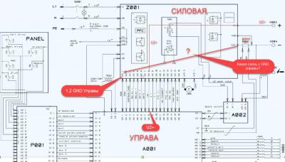
Вывод кажется ясен: управа не видит обратной связи с выхода сварки. Если на входе 90В, на управе U2+ полный ноль. Так не должно быть.
Положительная обратная связь на управу организована просто: с выхода сварки плюс идёт на прямую на управу (сигнал U2+). А вот куда и как идёт минус с выхода сварки на управу, никак не могу найти: он не имеет ни какой общей связи с минусом управой ни через резисторы, диоды, ни через оптрон и т.т.
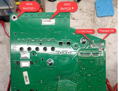
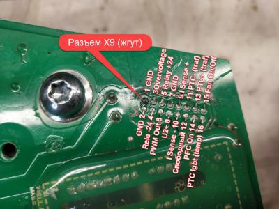
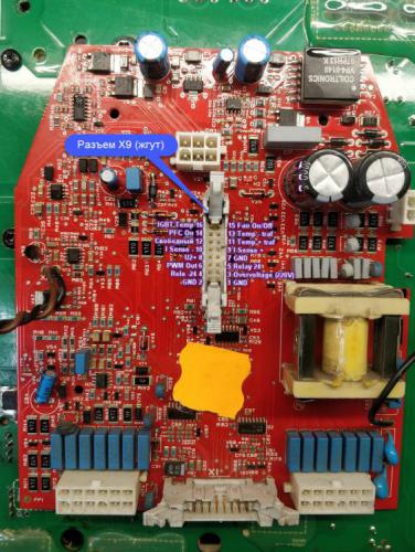
И вот основной вопрос: может кто ни будь имеет под рукой плату и может померить между минусом выхода сварки (Х004) и минусом управы (Разъем Х9, 1 или 2 вывод GND). Или же может кто ни будь знает, как организована обратная связь с минуса выхода сварки на минус управы?
Силовой источник 1…..50
Логика MIG 51…..100
Доступ Кривой 101…..130
Интерфейс Робота 131…..150
MIG/TIG Устройство 151…..200
Интерфейс пользавателя 201…..250
Другие 0…..999
Err 2: Силовой источник под напряжением (новый пуск)
Err 3: Силовое исходное перенапряжение (новый пуск)
Err 4: Силовой источник перегрет.
Err 5: Водяная тревога устройства.
Err 11: Два устройства имеют тот же адрес на системной шине.
Err 12: Ошибка данных на связи (2)
Err 13: *Цензура* неправильного семейства FastMIG связанного.
Err 14: Проблема связи Данных между силовым источником и вспомогательным устройством.
Err 15: Силовая исходная программа / обновление метода проблемы.
Err 21: Силовая исходная управляющая карта +5 aux V. Напряжение слишком низкий уровень.
Err 22: Силовая исходная управляющая карта +15 aux V. Напряжение слишком низкий уровень.
Err 23: Временно силовое исходное перенапряжение.
Err 31: Силовая исходная ошибка калибровки. Сваривать только возможно со значением по умолчанию.
Err 54: Нет связи с источником питания. Возможно неисправный кабель/разъем..
Err 55: Сварка запрещена(конфигурация / системной шине резервирована)
Err 61: Нет связи с водоохладителем..
Err 153: Перегрев холодной жидкости сварочного рукава.
Err 154: Двигатель подачи проволоки перегружен выше предела.
Возможно засорена спираль или сильний изгиб сварочного рукава.
Err 155: Перегрузка двигателя подачи проволоки. Движение (ток) двигателя слишком близкое к пределу.
Err 161: Предупреждение перегрева устройства проволочной подачи.
Err 162: Перегрузка двигателя подачи проволоки.
Err 171: Конфигурация оборудования не может обнаружится.
Err 172: Поставлен неправильный код конфигурации.
Err 173: Действие не активизировано кодом конфигурации права
Err 184: Неисправен управляющий кабель.
Err 185: Машинная программная ошибка коррекции. Неправильная программа или обновить коррекцию.
Err 201: Использование сварочного рукава PMT-предохраненного.
Err 221: Ошибка данных панели (1)
Err 222: Ошибка данных панели (2)
Err 223: Ошибка данных панели (3)
Err 224: Ошибка данных панели (4)
Err 225: Запрограммируйте обновление проблемы.
Err 241: Ошыбка памяти EEPROM
Err 251: Ошибка связи данных DLI (другое устройство в шине использует то же код=конфигурацию)
Err 251: Ошибка (2) данных DLI
Err 254: Ошибка связи данных DLI ( плохой разъем или кабель)
Err 255: Ошибка связи данных DLI
(программная проблема коррекции, может быть неправильная программная версия и т.п.).
Err 999: Неопознанная ошибка (система послала сообщение ошибки не идентифицированное панелью)
Источник: https://krb1-elektrik.narod.ru

EN
16
t
-9…0
0
Electrode ignition pulse
(-9 = No pulse / 0 = Max pulse)
U
1/0
0
Disable automatic remote control recognition.
0 = Enable automatic recognition, 1 = Disable
automatic recognition.
*) Happens when exiting SETUP mode and value is 1.
4.
errOr CODes
The machine always checks its operation automatically during start-up and
reports any failures detected. If failures are detected during start-up, they
are shown as error codes on the control panel display.
e 2: power source undervoltage
The device has stopped because it has detected a mains undervoltage that
disturbs welding. Check the quality of the supply network.
e 3: power source overvoltage
The machine has stopped the welding because it has detected momentary
voltage spikes or continuous overvoltage dangerous to the machine in the
electric network. Check the quality of the supply network.
e 4: power source overheating
The power source has overheated. The cause may be one of the following:
• The power source has been used for a long time at maximum power.
• The circulation of cooling air to the power source is blocked.
• The cooling system has experienced a failure.
Remove any obstacle to air circulation, and wait until the power source fan
has cooled down the machine.
Other error codes:
The machine can show codes not listed here. In the event of an unlisted
code appearing, contact an authorised Kemppi service agent and report the
error code shown.
16
MinarcTig 180, 180MLP, 250, 250 MLP
5.
The machine always checks its operation automatically during start-up and reports any failures
detected. If failures are detected during start-up, they are shown as error codes on the control
panel display.
Error 4: Power source overheating
The power source has overheated. The cause may be one of the following:
• The power source has been used for a long time at maximum power.
• The circulation of cooling air to the power source is blocked.
• The cooling system has experienced a failure.
Remove any obstacle to air circulation, and wait until the power source fan has cooled down the
machine.
Other error codes:
The machine can show codes not listed here. In the event of an unlisted code appearing, contact
an authorised Kemppi service agent and report the error code shown.
5.1
Troubleshooting
Problem
Panel display does not light.
Poor welding results.
Overheating indicator is illuminated. Normally, this indicates that the device has reached its maximum designed operating
If the machine’s malfunction is not eliminated with the above measures, contact Kemppi service.
© Kemppi Oy / 1422
Cause
• Check parent power supply is functioning
• Check parent power supply is connected
• Check parent power supply cable connectors are correct and secure.
Several factors affect the welding quality.
• Ensure that the parent power source is set to full power and that the voltage exceeds
the minimum supply voltage level of 40 volts. (Inadequate supply voltage will result
in an unstable power delivery or poor ignition).
• Ensure that the welding current selected is adequate for the selected electrode type
and size.
• Ensure the cable connections are correct and secure.
• Ensure the process selection is correct.
• Check that the earth return clamp connection area is clean and that the cable and
clamp are not damaged.
• For TIG welding, check that the shielding gas flow is switched on and set correctly.
Poor ignition and arc quality in TIG welding may be a result of a poorly prepared
tungsten electrode. Always maintain and grind a point on the TIG torch electrode tip
before welding.
temperature. The thermostat has become active, switching the welding power off.
Allow the unit to cool and the machine will soon automatically reset and allow
welding to re-start.
• Ensure that cooling air has unrestricted flow.
• If the machine’s duty cycle has been exceeded, wait for indicator to turn off.
In certain circumstances, this light may also indicate irregularity in the supply voltage.
Too low or high supply voltage.
EN
13
s237, Как это ни одной осцилки. Посмотрите еще раз мои посты №№ #6926495,#6926934,#6928607,#6929046,#6929711,#6940150, Вы их просто похоже игнорируете. Методы замеров на них видны, установки времени, напряжения, и тип входа в верхней строке в нижней результаты замеров тоже есть. Какие еще вам картинки и цифры нужны? Еще скажите что это вообще фотошоп? И еще раз повторяю, что эти методы придумал не я! Ссылку на источник и автора дал выше. У него далеко . А то, что вы эти методы не знаете и не используете, то это не значит что они кривые и недостоверные. От вас лично Сергей, по моей проблеме на последних трех страницах ни одного поста по делу не было . Только одни вопросы, критика и беспредельный снобизм типа:
«Очередной мастер.
Кого Вы здесь пытаетесь научить? Попросили, Вам ответили, еще вопрос — еще ответ.»(#6926620)
«Вот теперь все понятно. Вам к мастеру надо.
Всякие уже видел измерения у всяких людей. Такое измерение слышу, да и вижу, наверное, впервые….»(Пост №#6926828)
«У меня есть решение вашей проблемы, но я пока не пойму — Вы этой помощи хотите, или сами будете ремонтить дальше.»(#6926611)
«В вашей схеме ошибка.
ТТ не может быть включен в цепь емкостей. Принципиально. Вы видели как включен ТТ в полумосте…. «(#6926979)
«Знаю я проблему с вашим аппаратом. Скажите «да», сможем начать.»(#6926620)
Или вот еще очередной «интересный» вопрос знатока.. :
…»Так от какой обмотки питается ШИМ напряжением 9,5В?
Смущает меня такое питание 9,5В. Очень смущает.
Такого питания могло, а точнее, то может быть недостаточно для правильного открытия (закрытия) силовых ключей….»(#6929162)
Позвольте Уважаемый, задать вопрос Вам: Как может зависеть напряжение питание ШИМ и напряжение открытие затворов если между ними стоит оптика, которая обычно , а точнее всегда питается от отдельного источника, в данном СА 15В?!
Тут(#6929162) же есть Ваше рассуждение по вопросу питании ШИМ и управы: ..»Сварочный трансформатор, который на сварочные клемы дает напряжение, там может быть дополнительная обмотка» .(#6929162). Такое возможно в полуавтомате, где обязательна протяжка проволоки,клапан подачи СО и управа?
Извините, опять забыл, что здесь только одно правильное мнение- это Ваше, и только Вам позволено задавать вопросы и высказываться. Хотел написать В ЛС но что-то не нашел тут такой функции .
vlbudkin , « Вы случайно не втюхали такую цепочку в свой аппарат- это объяснило б непонятный выход транзисторов«
Конечно нет. Поэтому и спросил тут #6940155 т.к. тоже думал что 7,5В положительной полу волны будет мало. Все было штатное при последнем бахе , только супрессоры на затворы повесил.
«Насчет просмотра деттайма между выходами шима с вами не спорили — просто говорили что это не очень корректно,тк важно поглядеть индентичность сигналов на каждом выходе.»
[На этой картинке ] как раз верхняя полуволна сигал на одном, а нижняя сигнал на другом выходе Шим, а при исправных драйверах и на затворах они совершенно одинаковы должны быть. . Или я опять не прав ?()
Всем привет
Kemppi MinarcTIG Evo 200 сгорел iGBT модуль, ошибка Е6.
Поменял модуль, осциллограммы нормальные. Включаю, запускается ШИМ, на выходе на холостом 90 вольт и после 2 секунд радости, шим отключается, на дисплее показывает ошибку Е6.
Выяснил, что ошибка Е6 появляется, тогда, когда шим запускается, и управа 2 секунды не видит обратной связи с выхода сварки, тогда процессор вырубает шим.
Этим убедился просто — с раздельного блока питания на управу на сигнал U2+ подал 2-3 вольта, и вуаля, шим работает, ошибок нет. Если на U2+ уменьшаю ниже вольта, шим отключается.
Вывод кажется ясен: управа не видит обратной связи с выхода сварки. Если на входе 90В, на управе U2+ полный ноль. Так не должно быть.
Положительная обратная связь на управу организована просто: с выхода сварки плюс идёт на прямую на управу (сигнал U2+). А вот куда и как идёт минус с выхода сварки на управу, никак не могу найти: он не имеет ни какой общей связи с минусом управой ни через резисторы, диоды, ни через оптрон и т.т.
И вот основной вопрос: может кто ни будь имеет под рукой плату и может померить между минусом выхода сварки (Х004) и минусом управы (Разъем Х9, 1 или 2 вывод GND). Или же может кто ни будь знает, как организована обратная связь с минуса выхода сварки на минус управы?
EN
16
t
-9…0
0
Electrode ignition pulse
(-9 = No pulse / 0 = Max pulse)
U
1/0
0
Disable automatic remote control recognition.
0 = Enable automatic recognition, 1 = Disable
automatic recognition.
*) Happens when exiting SETUP mode and value is 1.
4.
errOr CODes
The machine always checks its operation automatically during start-up and
reports any failures detected. If failures are detected during start-up, they
are shown as error codes on the control panel display.
e 2: power source undervoltage
The device has stopped because it has detected a mains undervoltage that
disturbs welding. Check the quality of the supply network.
e 3: power source overvoltage
The machine has stopped the welding because it has detected momentary
voltage spikes or continuous overvoltage dangerous to the machine in the
electric network. Check the quality of the supply network.
e 4: power source overheating
The power source has overheated. The cause may be one of the following:
• The power source has been used for a long time at maximum power.
• The circulation of cooling air to the power source is blocked.
• The cooling system has experienced a failure.
Remove any obstacle to air circulation, and wait until the power source fan
has cooled down the machine.
Other error codes:
The machine can show codes not listed here. In the event of an unlisted
code appearing, contact an authorised Kemppi service agent and report the
error code shown.
16
MinarcTig 180, 180MLP, 250, 250 MLP
- 5 Апр 2017
марка этого блока известна? замену надо подбирать исходя из его характеристик
Добавлено 05-04-2017 10:48
если просто навскидку, исходя из тока, два нормальных транзистора на ключ.
Добавлено 05-04-2017 10:51
Шрек сказал(а):
судя по IGBT_1.jpg 76,46 КБ это КОСОЙ. там один блок стоял?
Добавлено 05-04-2017 11:00
Шрек сказал(а):
решил собрать из обычных транзисторов закрепив из на родном радиаторе через прокладки.
с учетом этого может и 3 штуки на ключ потребоваться. В любом случае надо будет мерить Т ключей при полной нагрузке. Есть балласт?
3.
КОДЫ ОШИБОК FASTMIG
Наличие возможных неисправностей в оборудовании оценивается при каждом запуске
механизма подачи проволоки. В случае обнаружения неисправности она будет указываться в
виде сообщения об ошибке на дисплее панели.
Примеры кодов ошибок:
Err 2: Пониженное напряжение
Устройство остановилось, поскольку было обнаружено понижение напряжения в сети,
оказывающее влияние на процесс сварки. Проверьте качество сети электропитания.
Err 3: Повышенное напряжение
Работа оборудования остановлена, так как в электрической сети был обнаружен временный
опасный бросок напряжения или постоянное превышение напряжения. Проверьте качество
сети электропитания.
Err 4: Перегрев источника питания
Источник питания перегрелся. Перегрев может быть вызван одной из следующих причин:
• источник питания длительное время работал на максимальной мощности;
• перекрыта подача охлаждающего воздуха к источнику питания;
• неисправность в системе охлаждения.
Удалите препятствия на пути циркуляции воздуха и подождите, пока вентилятор источника
питания не охладит аппарат.
Err 5: Аварийная сигнализация водоохладителя
Заблокирована циркуляция воды. Перегрев может быть вызван одной из следующих причин:
• закупоривание или отсоединение трубопровода охлаждения;
• недостаточное количество охлаждающей жидкости;
• превышение температуры охлаждающей жидкости.
Проверьте циркуляцию охлаждающей жидкости и циркуляцию воздуха через
водоохладитель.
Err 54: Отсутствует обмен данными с источником питания
Передача данных между источником питания и механизмом подачи проволоки прервана или
осуществляется с ошибками. Проверьте удлинительный кабель и соединения.
Err 55: Источник питания занят
Канал связи занят. Источник питания используется другим механизмом подачи проволоки
или по каналу связи выполняется программирование для другого устройства (например,
панели управления).
Err 61: Водоохладитель не обнаружен
Водоохладитель не подсоединен к оборудованию или соединение неисправно.
Подключите водоохладитель или, если используется сварочная горелка с воздушным
охлаждением, измените настройки аппарата на воздушное охлаждение.
Err 153: Перегрев горелки PMT с жидкостным охлаждением
В начале или во время сварки произошло включение системы предотвращения перегрева
сварочной горелки MIG с жидкостным охлаждением. Убедитесь, что в блоке охлаждения
находится достаточное количество жидкости и что воздух свободно циркулирует через блок
RU RU
охлаждения. Убедитесь, что жидкость свободно циркулирует через шланги охлаждения.
Err 154: Перегрузка электродвигателя устройства подачи проволоки
Сварка была прервана, поскольку нагрузка на электродвигатель подачи проволоки возросла
до высокого уровня. Причиной такого повышения может быть засорение направляющего
канала. Проверьте канал проволоки, контактный наконечник и подающие валики.
Err 155: Предупреждающий сигнал о перегрузке механизма подачи проволоки
Уровень нагрузки электродвигателя устройства подачи проволоки возрос. Причиной
такого повышения может быть загрязнение канала проволоки или резкие перегибы кабеля
горелки. В случае необходимости проверьте состояние сварочной горелки и прочистите
направляющий канал.
Err 165: Предупреждение предохранительного устройства регулировки газа
Сработало предохранительное устройство регулировки газа, поскольку давление газа
снизилось. Возможные причины: Газ не подается к механизму подачи проволоки. Запас
газа исчерпан, течь в шланге защитного газа или низкое давление в сети защитного газа.
18
FastMig MS 200, MS 300

-
Contents
-
Table of Contents
-
Bookmarks
Quick Links
SERVICE MANUAL
KEMPACT RA
181A
251R/251A
253R/253A
323R/323A
253MV/323MV
Kemppi Oy
Related Manuals for Kemppi Kempact 253R
Summary of Contents for Kemppi Kempact 253R
-
Page 1
SERVICE MANUAL KEMPACT RA 181A 251R/251A 253R/253A 323R/323A 253MV/323MV Kemppi Oy… -
Page 2: Table Of Contents
3.4.2.1. EMC filter …………………………….18 3.4.2.2. Inrush current limiting …………………………18 3.4.2.3. IGBT driver …………………………….. 18 3.4.2.4. Current transformer T1 …………………………. 18 3.4.2.5. Main circuit ……………………………. 18 3.4.2.6. PFC Boost control circuitry ……………………….18 4. MAIN CIRCUIT CARD Z001 …………………………….19 Kemppi Oy…
-
Page 3
Digital multimeters may give different values depending the specifications they have. For example diode measuring values may vary between the multimeters models. Special attention must be considered while working with the internal parts. The device may be repaired only by a person legally authorized to perform electrical work. Kemppi Oy… -
Page 4: Service Manual
SERVICE MANUAL 3 (40) KEMPACT RA_V_1.2 1. PARTS OF MACHINE Kempact RA (253, 323) Kemppi Oy…
-
Page 5
SERVICE MANUAL 4 (40) KEMPACT RA_V_1.2 Kempact RA (253, 323) NOTE ! spareparts@kemppi.com Spare part info available from: (email). Kemppi Oy… -
Page 6: Technical Information
EMC class Degree of protection IP23S IP23S Operating temperature range -20…+40 °C -20…+40 °C Storage temperature range -40…+60 °C -40…+60 °C Standards IEC 60974-1 IEC 60974-1 IEC 60974-5 IEC 60974-5 IEC 60974-10 IEC 60974-10 IEC 61000-3-12 IEC 61000-3-12 Kemppi Oy…
-
Page 7
SERVICE MANUAL 6 (40) KEMPACT RA_V_1.2 Kempact 253R, 253A Kempact 323R, 323A Connection voltage 50/60Hz 400V+- 15% 3~ 50/60Hz 400V +- 15% 3~ Rated power at max. current 40% ED I1max (250A) 8.34kVA/7.73kW 35% ED I1max (320A) 12kVA/11.3kW Supply current 40% ED I1max (250A) 11.9A… -
Page 8
623x579x1070 mm LxWxH 623x579x1070 mm Not including gun and Not including gun and Weight gables 44 kg gables 44 kg Temperature class F(155 C) F(155 C) EMC class Degree of protection IP23S IP23S Operating temperature -20…+40 °C -20…+40 °C Kemppi Oy… -
Page 9
SERVICE MANUAL 8 (40) KEMPACT RA_V_1.2 range Storage temperature range -40…+60 °C -40…+60 °C Standards IEC 60974-1 IEC 60974-1 IEC 60974-5 IEC 60974-5 IEC 60974-10 IEC 60974-10 IEC 61000-3-12 IEC 61000-3-12 Kemppi Oy… -
Page 10: Main Circuit Diagrams
SERVICE MANUAL 9 (40) KEMPACT RA_V_1.2 2.2. Main circuit diagrams Kemppi Oy…
-
Page 11
SERVICE MANUAL 10 (40) KEMPACT RA_V_1.2 Kemppi Oy… -
Page 12
SERVICE MANUAL 11 (40) KEMPACT RA_V_1.2 * Please refer to Kemppi Channel for the latest version of main circuit drawings ! Kemppi Oy… -
Page 13
Wire feed motor M003 • Brights led card P002 • Panel card P001 • Main circuit card Z001 • Secondary rectifier card Z002 • Secondary choke L001 • Output RFI filters C001 and C002 • Euro connector X005 • Kemppi Oy… -
Page 14: Main Components
The microcontroller also regulates wire feed speed by setting motor current reference and measuring EMF of the • motor 3.1.8.3. Motor control Wire feed motor control is based on EMF (electro magnetic force) measurement principle • Kemppi Oy…
-
Page 15: Fans M001, M002
Capacitors C1 and C2 and resistors R3 and R4 form a snubber circuit. The snubber circuit reduces the voltage stress of • the diodes caused by the reverse recovery current snap off Varistors R1 and R2 are for TIG ignition spark protection • Kemppi Oy…
-
Page 16: Secondary Choke L001
The switching frequency of the boost circuit is ca. 15 kHz. The boost circuit raises DC link voltage to ca. 370V. Boost • input current is measured using shunt resistors R58, R59, R65, R66. H – bridge is implemented using the other two legs of the IGBT module Kemppi Oy…
-
Page 17: Pfc Boost Control Circuitry
When IGBT-transistors G1 and G4 conduct, there is a positive voltage U in main transformer T1 primary and when IGBT- transistors G2 and G3 conduct there is a negative voltage U in main transformer primary. Power is adjusted by changing the Kemppi Oy IGBT timings (PWM).
-
Page 18
SERVICE MANUAL 17 (40) KEMPACT RA_V_1.2 Kemppi Oy… -
Page 19: Main Circuit Diagram 253Mv-, 323Mv-Models
PFC control circuitry is located on the primary side. Auxliary transformer T003 supplies operating voltage for the PFC • control circuitry. The output voltage of the T003 is first rectified and then linear regulator is used to regulate auxiliary voltage to 15V. PFC control IC N1 regulates DC-link voltage to approximately 630V. Kemppi Oy…
-
Page 20: Connectors
Main voltage connector Mains voltage Mains voltage connector Signal Chassis ground connector Signal Auxiliary transformer connection, auxliary transformer is protected with PTC resistors R63 and R64 PFC Auxiliary transformer connection, auxliary transformer is protected with PTC resistors R63 and R64 Kemppi Oy…
-
Page 21
Other end of the IGBT driver transformer primary X10:11 PFC ON/OFF N PFC on/off opto coupler diode negative end X10:12 Signal PFC choke connections PFC choke connections PFC choke connections PFC choke connections Signal DC-link voltage DC-link voltage Kemppi Oy… -
Page 22: Kempact 253, 323
Auxiliary transformer connection, auxliary transformer is protected with PTC resistors R16 and R17 Signal Main transformer connections (253 machine use two flat connectors, 323 use four) Main transformer connections (253 machine use two flat connectors, 323 use four) Kemppi Oy…
-
Page 23
IGBT Drive A Other end of the IGBT driver transformer primary X9:5 OV Opto N Over voltage optocoupler other end X9:6 Inrush Relay Other end of the inrush relay coil Signal Primary current transformer connector Signal DC-link voltage DC-link voltage Kemppi Oy… -
Page 24: Kempact 253Mv, 323Mv
X3, X22 Mains voltage Mains voltage connector Signal Chassis ground connection Signal Description Auxliary transformer connectors. Auxliary transformer is protected with PTC resistors R63 and R64. Auxliary transformer connectors. Auxliary transformer is protected with PTC resistors R63 and R64. Kemppi Oy…
-
Page 25
Over voltage optocoupler other end X18:4 IGBT Drive A Other end of the IGBT driver transformer primary X18:5 PFC ON/OFF N PFC on/off opto coupler diode positive end X18:6 OV Opto N Over voltage optocoupler other end Signal DC-link voltage DC-link voltage Kemppi Oy… -
Page 26: Secondary Rectifier Card Z002
SERVICE MANUAL 25 (40) KEMPACT RA_V_1.2 5. SECONDARY RECTIFIER CARD Z002 5.1. Connectors Signal Main transformer secondary Main transformer secondary Z002 card connection to secondary profile Z002 card connection to secondary profile Rectified +24V Polarity connector (-) Kemppi Oy…
-
Page 27: Control Card A001
Signal Description X2:1 + 50 V Secondary voltage from secondary card X2:2 Ground X2:3 + 24 V +24V from the auxiliary transformer X2:4 Motor (+) Wire feed motor (+) X2:5 Motor (-) Wire feed motor (-) X2:6 Ground Kemppi Oy…
-
Page 28
IGBT driver transformer other end X6:5 PTC connection X6:6 Start A Gun switch connection Signal Connections to chassis ground Signal Used in development purposes, do not connect anything here Signal Maintenance use Signal Panel card P001 connection Signal Not in use Kemppi Oy… -
Page 29: Panel Card P001
Pulse potentiometer 2 channel A X1:11 Pot_2_B Pulse potentiometer 2 channel B X1:12 Ground X1:13 Pot_3_A Pulse potentiometer 3 channel A X1:14 Pot_3_B Pulse potentiometer 3 channel B X1:15 +5V supply voltage X1:16 +24V +24V supply voltage for the LCD backlight Kemppi Oy…
-
Page 30: Kempact 181, 251
Result: 0,3…0,6 diodes Ok 4) Positive pole to rectifier pole (4, red), negative test pole to rectifier poles (1, black) one at the time Result: no value diodes Ok NOTE ! The measurement procedure is same for V24 and V25 rectifiers. Kemppi Oy…
-
Page 31: Igbt Module V1
1) Positive test pole (1, red) to connector X16, negative test pole (1, black) to connectors X7, X8 and X14 one at time Result: 0,3…0,6 diodes Ok 2) Negative test pole (2, black) to connector X13, positive test pole (2, red) to connectors and X7, X8 and X14 one at time Result: 0,3…0,6 diodes Ok Kemppi Oy…
-
Page 32: Kempact 253, 323
3) Negative test pole to DC-link (+), positive test pole L1, L2, L3 (one at the time) Result: 0,3…0,6 diodes Ok 4) Negative test pole to DC-link (-), positive test pole L1, L2, L3 (one at the time) Result: no value diodes Ok Kemppi Oy…
-
Page 33: Igbt Module, V2
1) Positive test pole to connector X7 and X8 one at time, negative test pole to DC link (+) Result: 0,3…0,6 diodes Ok 2) Positive test pole to DC-link (-), negative test pole to X7 and X8 one at time Result: 0,3…0,6 diodes Ok Kemppi Oy…
-
Page 34: Kempact 253Mv, 323Mv
3) Positive test pole to rectifier pole (2, red), negative test pole rectifier poles (2, black)one at the time Result: 0,3…0,6 diodes Ok 4) Negative test pole to rectifier pole (3, black), positive test pole to rectifier poles (2, red) one at the time Result: no value diodes Ok Kemppi Oy…
-
Page 35: Igbt Module, V1
1) Negative test pole (1, black) to connector X19, positive test pole (1, red) to connectors X13, X14 and X17 one at time Result: 0,3…0,6 diodes Ok 2) Positive test pole (2, red) to connector X20, negative test pole (2, black) to connectors and X13, X14 and X17 one at time Result: 0,3…0,6 diodes Ok Kemppi Oy…
-
Page 36
1) Positive test pole to main transformer secondary (secondary card connectors X1 and X2 one at time), negative test pole to secondary profile Result: 0,3…0,6 diodes Ok 2) Positive test pole to secondary profile, negative test pole to main transformer secondary (secondary card connectors X1 and X2 one at time) Result: no value diodes Ok Kemppi Oy… -
Page 37: Ptc’s, Overheat Protection
Primary rectifier V1 to heatsink 2 NM • IGBT unit to heatsink • First step 2 NM and wait a couple minutes Second step 3 NM Main circuit card Z001 to profile holder 0,7 NM • Primary unit to component frame 2 NM • Kemppi Oy…
-
Page 38: Secondary Rectifier Card Z002
• Auxiliary transformer T002 to component frame 5 NM • Secondary choke L001 to component frame 2 NM • Secondary choke L001 other lead to secondary profile 5 NM and other lead to polarity screw 5 NM • Kemppi Oy…
-
Page 39: Error Codes
-communication error between panel card -check flat cable/connectors between P001 and control card A001 panel- and control card Panel communication error -communication error between panel card -check flat cable/connectors between P001 and control card A001 panel- and control card Kemppi Oy…
-
Contents
-
Table of Contents
-
Bookmarks
Quick Links
SERVICE MANUAL
KEMPACT RA
181A
251R/251A
253R/253A
323R/323A
253MV/323MV
Kemppi Oy
Related Manuals for Kemppi Kempact 253R
Summary of Contents for Kemppi Kempact 253R
-
Page 1
SERVICE MANUAL KEMPACT RA 181A 251R/251A 253R/253A 323R/323A 253MV/323MV Kemppi Oy… -
Page 2: Table Of Contents
3.4.2.1. EMC filter …………………………….18 3.4.2.2. Inrush current limiting …………………………18 3.4.2.3. IGBT driver …………………………….. 18 3.4.2.4. Current transformer T1 …………………………. 18 3.4.2.5. Main circuit ……………………………. 18 3.4.2.6. PFC Boost control circuitry ……………………….18 4. MAIN CIRCUIT CARD Z001 …………………………….19 Kemppi Oy…
-
Page 3
Digital multimeters may give different values depending the specifications they have. For example diode measuring values may vary between the multimeters models. Special attention must be considered while working with the internal parts. The device may be repaired only by a person legally authorized to perform electrical work. Kemppi Oy… -
Page 4: Service Manual
SERVICE MANUAL 3 (40) KEMPACT RA_V_1.2 1. PARTS OF MACHINE Kempact RA (253, 323) Kemppi Oy…
-
Page 5
SERVICE MANUAL 4 (40) KEMPACT RA_V_1.2 Kempact RA (253, 323) NOTE ! spareparts@kemppi.com Spare part info available from: (email). Kemppi Oy… -
Page 6: Technical Information
EMC class Degree of protection IP23S IP23S Operating temperature range -20…+40 °C -20…+40 °C Storage temperature range -40…+60 °C -40…+60 °C Standards IEC 60974-1 IEC 60974-1 IEC 60974-5 IEC 60974-5 IEC 60974-10 IEC 60974-10 IEC 61000-3-12 IEC 61000-3-12 Kemppi Oy…
-
Page 7
SERVICE MANUAL 6 (40) KEMPACT RA_V_1.2 Kempact 253R, 253A Kempact 323R, 323A Connection voltage 50/60Hz 400V+- 15% 3~ 50/60Hz 400V +- 15% 3~ Rated power at max. current 40% ED I1max (250A) 8.34kVA/7.73kW 35% ED I1max (320A) 12kVA/11.3kW Supply current 40% ED I1max (250A) 11.9A… -
Page 8
623x579x1070 mm LxWxH 623x579x1070 mm Not including gun and Not including gun and Weight gables 44 kg gables 44 kg Temperature class F(155 C) F(155 C) EMC class Degree of protection IP23S IP23S Operating temperature -20…+40 °C -20…+40 °C Kemppi Oy… -
Page 9
SERVICE MANUAL 8 (40) KEMPACT RA_V_1.2 range Storage temperature range -40…+60 °C -40…+60 °C Standards IEC 60974-1 IEC 60974-1 IEC 60974-5 IEC 60974-5 IEC 60974-10 IEC 60974-10 IEC 61000-3-12 IEC 61000-3-12 Kemppi Oy… -
Page 10: Main Circuit Diagrams
SERVICE MANUAL 9 (40) KEMPACT RA_V_1.2 2.2. Main circuit diagrams Kemppi Oy…
-
Page 11
SERVICE MANUAL 10 (40) KEMPACT RA_V_1.2 Kemppi Oy… -
Page 12
SERVICE MANUAL 11 (40) KEMPACT RA_V_1.2 * Please refer to Kemppi Channel for the latest version of main circuit drawings ! Kemppi Oy… -
Page 13
Wire feed motor M003 • Brights led card P002 • Panel card P001 • Main circuit card Z001 • Secondary rectifier card Z002 • Secondary choke L001 • Output RFI filters C001 and C002 • Euro connector X005 • Kemppi Oy… -
Page 14: Main Components
The microcontroller also regulates wire feed speed by setting motor current reference and measuring EMF of the • motor 3.1.8.3. Motor control Wire feed motor control is based on EMF (electro magnetic force) measurement principle • Kemppi Oy…
-
Page 15: Fans M001, M002
Capacitors C1 and C2 and resistors R3 and R4 form a snubber circuit. The snubber circuit reduces the voltage stress of • the diodes caused by the reverse recovery current snap off Varistors R1 and R2 are for TIG ignition spark protection • Kemppi Oy…
-
Page 16: Secondary Choke L001
The switching frequency of the boost circuit is ca. 15 kHz. The boost circuit raises DC link voltage to ca. 370V. Boost • input current is measured using shunt resistors R58, R59, R65, R66. H – bridge is implemented using the other two legs of the IGBT module Kemppi Oy…
-
Page 17: Pfc Boost Control Circuitry
When IGBT-transistors G1 and G4 conduct, there is a positive voltage U in main transformer T1 primary and when IGBT- transistors G2 and G3 conduct there is a negative voltage U in main transformer primary. Power is adjusted by changing the Kemppi Oy IGBT timings (PWM).
-
Page 18
SERVICE MANUAL 17 (40) KEMPACT RA_V_1.2 Kemppi Oy… -
Page 19: Main Circuit Diagram 253Mv-, 323Mv-Models
PFC control circuitry is located on the primary side. Auxliary transformer T003 supplies operating voltage for the PFC • control circuitry. The output voltage of the T003 is first rectified and then linear regulator is used to regulate auxiliary voltage to 15V. PFC control IC N1 regulates DC-link voltage to approximately 630V. Kemppi Oy…
-
Page 20: Connectors
Main voltage connector Mains voltage Mains voltage connector Signal Chassis ground connector Signal Auxiliary transformer connection, auxliary transformer is protected with PTC resistors R63 and R64 PFC Auxiliary transformer connection, auxliary transformer is protected with PTC resistors R63 and R64 Kemppi Oy…
-
Page 21
Other end of the IGBT driver transformer primary X10:11 PFC ON/OFF N PFC on/off opto coupler diode negative end X10:12 Signal PFC choke connections PFC choke connections PFC choke connections PFC choke connections Signal DC-link voltage DC-link voltage Kemppi Oy… -
Page 22: Kempact 253, 323
Auxiliary transformer connection, auxliary transformer is protected with PTC resistors R16 and R17 Signal Main transformer connections (253 machine use two flat connectors, 323 use four) Main transformer connections (253 machine use two flat connectors, 323 use four) Kemppi Oy…
-
Page 23
IGBT Drive A Other end of the IGBT driver transformer primary X9:5 OV Opto N Over voltage optocoupler other end X9:6 Inrush Relay Other end of the inrush relay coil Signal Primary current transformer connector Signal DC-link voltage DC-link voltage Kemppi Oy… -
Page 24: Kempact 253Mv, 323Mv
X3, X22 Mains voltage Mains voltage connector Signal Chassis ground connection Signal Description Auxliary transformer connectors. Auxliary transformer is protected with PTC resistors R63 and R64. Auxliary transformer connectors. Auxliary transformer is protected with PTC resistors R63 and R64. Kemppi Oy…
-
Page 25
Over voltage optocoupler other end X18:4 IGBT Drive A Other end of the IGBT driver transformer primary X18:5 PFC ON/OFF N PFC on/off opto coupler diode positive end X18:6 OV Opto N Over voltage optocoupler other end Signal DC-link voltage DC-link voltage Kemppi Oy… -
Page 26: Secondary Rectifier Card Z002
SERVICE MANUAL 25 (40) KEMPACT RA_V_1.2 5. SECONDARY RECTIFIER CARD Z002 5.1. Connectors Signal Main transformer secondary Main transformer secondary Z002 card connection to secondary profile Z002 card connection to secondary profile Rectified +24V Polarity connector (-) Kemppi Oy…
-
Page 27: Control Card A001
Signal Description X2:1 + 50 V Secondary voltage from secondary card X2:2 Ground X2:3 + 24 V +24V from the auxiliary transformer X2:4 Motor (+) Wire feed motor (+) X2:5 Motor (-) Wire feed motor (-) X2:6 Ground Kemppi Oy…
-
Page 28
IGBT driver transformer other end X6:5 PTC connection X6:6 Start A Gun switch connection Signal Connections to chassis ground Signal Used in development purposes, do not connect anything here Signal Maintenance use Signal Panel card P001 connection Signal Not in use Kemppi Oy… -
Page 29: Panel Card P001
Pulse potentiometer 2 channel A X1:11 Pot_2_B Pulse potentiometer 2 channel B X1:12 Ground X1:13 Pot_3_A Pulse potentiometer 3 channel A X1:14 Pot_3_B Pulse potentiometer 3 channel B X1:15 +5V supply voltage X1:16 +24V +24V supply voltage for the LCD backlight Kemppi Oy…
-
Page 30: Kempact 181, 251
Result: 0,3…0,6 diodes Ok 4) Positive pole to rectifier pole (4, red), negative test pole to rectifier poles (1, black) one at the time Result: no value diodes Ok NOTE ! The measurement procedure is same for V24 and V25 rectifiers. Kemppi Oy…
-
Page 31: Igbt Module V1
1) Positive test pole (1, red) to connector X16, negative test pole (1, black) to connectors X7, X8 and X14 one at time Result: 0,3…0,6 diodes Ok 2) Negative test pole (2, black) to connector X13, positive test pole (2, red) to connectors and X7, X8 and X14 one at time Result: 0,3…0,6 diodes Ok Kemppi Oy…
-
Page 32: Kempact 253, 323
3) Negative test pole to DC-link (+), positive test pole L1, L2, L3 (one at the time) Result: 0,3…0,6 diodes Ok 4) Negative test pole to DC-link (-), positive test pole L1, L2, L3 (one at the time) Result: no value diodes Ok Kemppi Oy…
-
Page 33: Igbt Module, V2
1) Positive test pole to connector X7 and X8 one at time, negative test pole to DC link (+) Result: 0,3…0,6 diodes Ok 2) Positive test pole to DC-link (-), negative test pole to X7 and X8 one at time Result: 0,3…0,6 diodes Ok Kemppi Oy…
-
Page 34: Kempact 253Mv, 323Mv
3) Positive test pole to rectifier pole (2, red), negative test pole rectifier poles (2, black)one at the time Result: 0,3…0,6 diodes Ok 4) Negative test pole to rectifier pole (3, black), positive test pole to rectifier poles (2, red) one at the time Result: no value diodes Ok Kemppi Oy…
-
Page 35: Igbt Module, V1
1) Negative test pole (1, black) to connector X19, positive test pole (1, red) to connectors X13, X14 and X17 one at time Result: 0,3…0,6 diodes Ok 2) Positive test pole (2, red) to connector X20, negative test pole (2, black) to connectors and X13, X14 and X17 one at time Result: 0,3…0,6 diodes Ok Kemppi Oy…
-
Page 36
1) Positive test pole to main transformer secondary (secondary card connectors X1 and X2 one at time), negative test pole to secondary profile Result: 0,3…0,6 diodes Ok 2) Positive test pole to secondary profile, negative test pole to main transformer secondary (secondary card connectors X1 and X2 one at time) Result: no value diodes Ok Kemppi Oy… -
Page 37: Ptc’s, Overheat Protection
Primary rectifier V1 to heatsink 2 NM • IGBT unit to heatsink • First step 2 NM and wait a couple minutes Second step 3 NM Main circuit card Z001 to profile holder 0,7 NM • Primary unit to component frame 2 NM • Kemppi Oy…
-
Page 38: Secondary Rectifier Card Z002
• Auxiliary transformer T002 to component frame 5 NM • Secondary choke L001 to component frame 2 NM • Secondary choke L001 other lead to secondary profile 5 NM and other lead to polarity screw 5 NM • Kemppi Oy…
-
Page 39: Error Codes
-communication error between panel card -check flat cable/connectors between P001 and control card A001 panel- and control card Panel communication error -communication error between panel card -check flat cable/connectors between P001 and control card A001 panel- and control card Kemppi Oy…