
- Коды ошибок спецтехники JCB
- Коды ошибок двигателя JCB (Isuzu 4HK, 6HK)
- Истории из практики ремонта JCB
При возникновении неисправности на технике, информационный дисплей EMS сразу отображает на экране ошибки, при этом зуммер (сигнализатор) начинает пищать. Для отключения зуммера нужно нажать на кнопку ACK на мониторе JCB.
Подробное описание ошибок электронных блоков управления гидравлики ECU1 728/29900 728/35700 728/29900 728/35700 и блока электроники ECUW 728/35800 728/18500 728/15500 JCB.
Коды ошибок JCB (гидравлики и электроники)

| Коды ошибок |
Надпись на дисплее монитора | Описание неисправности |
| 101 | CRANK | ЭБУ1 не обнаруживает сигнал от коленвала. |
| 102 | FUEL | Цепь датчика топлива разомкнута |
| 103 | EN TMP | Цепь датчика температуры двигателя разомкнута. |
| 104 | HYD TMP | Цепь датчика температуры гидравлической жидкости разомкнута. |
| 105 | SET PT | Цепь потенциометра заданного положения дроссельной заслонки разомкнута. |
| 106 | SENS PT | Цепь потенциометра фактического положения дроссельной заслонки разомкнута. |
| 107 | OIL SW | Датчик давления масла выдает сигнал наличия давления при отключенном двигателе. |
| 108 | FLYWHEEL | Датчик карданной передачи выдает сигнал оборотов двигателя при отключенном |
| 109 | ALT | Генератор выдает сигнал наличия напряжения при отключенном двигателе. |
| 110 | THR SOL | Цепь электромагнитного клапана дроссельной заслонки разомкнута. Обнаруживается только при отключенном двигателе. |
| 111 | BOOM SP | Цепь регулирования малой скорости стрелы разомкнута. |
| 113 | MAX FLW | Цепь электромагнитного клапана максимального расхода разомкнута. Для машин JS200W данная ошибка может быть обнаружена тольк |
| 115 | BOOM | Цепь электромагнитного клапана приоритета разомкнута |
| 116 | FL PMP | Цепь выходного контура насоса дозаправки разомкнута. |
| 117 | HORN | Цепь выходного контура клаксона разомкнута. |
| 118 | HYD PMP | Цепь гидравлического насоса разомкнута. Поскольку клапан является пропорциональным, ошибка обнаруживается только при отключенном двигателе |
| 119 | SLW LCK | Цепь электромагнитного клапана блокиратора стрелы разомкнута. |
| 120 | HYD FAN | Цепь выходного контура вентилятора гидросистемы разомкнута. Обнаруживается только при отключенном двигателе |
| 121 | SLW BRK | Цепь электромагнитного клапана разблокировки стрелы разомкнута |
| 122 | SLW ST | Цепь электромагнитного клапана отключения стрелы разомкнута. |
| 127 | TL CHNG | Цепь электромагнитного клапана переключения скорости движения разомкнута. |
| 128 | WASHER | Цепь двигателя омывателя разомкнута. |
| 129 | DOZER | Цепь электромагнитного клапана отвала разомкнута. |
| 130 | GRB CW | Цепь электромагнитного клапана вращения грейфера по часовой стрелке разомкнута. |
| 131 | GRB CCW | Цепь электромагнитного клапана вращения грейфера против часовой стрелки разомкнута. |
| 132 | LW FLOW | Цепь электромагнитного клапана низкого расхода разомкнута. |
| 133 | ISOL | Цепь электромагнитного клапана гидроизолятора разомкнута. |
| 135 | 2 STAGE | Цепь предохранительного электромагнитного клапана ступени 2 разомкнута. |
| 136 | QK HTCH | Цепь электромагнитного клапана быстрой сцепки разомкнута. |
| 138 | HAMMER | Цепь электромагнитного клапана молота разомкнута. |
| 139 | CUSHION | Цепь электромагнитного клапана твердой/мягкой подушки разомкнута. |
| 142 | ENG SD | Цепь выходного контура отключения двигателя разомкнута. |
| 143 | GLW PLG | Цепь выходного контура свечей накаливания разомкнута. |
| 156 | TL FLW3 | Цепь электромагнитного клапана расхода 3 движения разомкнута. |
| 157 | TL FLW2 | Цепь электромагнитного клапана расхода 2 движения разомкнута. |
| 158 | GR CHNG | Цепь электромагнитного клапана М2 или переключения передач разомкнута. |
| 159 | BRKE LT | Цепь выходного контура лампы тормоза разомкнута. |
| 160 | AXLE LK | Цепь электромагнитного клапана блокировки моста разомкнута. |
| 161 | STAB UP | Цепь электромагнитного клапана подъема стабилизатора разомкнута. |
| 162 | STAB DIN | Цепь электромагнитного клапана опускания стабилизатора разомкнута. |
| 163 | STAB LH | Цепь электромагнитного клапана левого стабилизатора разомкнута. |
| 164 | STAB RH | Цепь электромагнитного клапана правого стабилизатора разомкнута. |
| 165 | CRUISE | Цепь электромагнитного клапана круиз-контроля разомкнута. |
| 166 | DIG ISL | Цепь электромагнитного клапана изолятора режущей кромки разомкнута. |
| 167 | PRK BK | Цепь электромагнитного клапана М1 или стояночного тормоза разомкнута. |
| 168 | DRV ISL | Цепь электромагнитного клапана изолятора привода разомкнута. |
| 202 | FUEL | Короткое замыкание цепи датчика уровня топлива. |
| 203 | EN TMP | Короткое замыкание цепи датчика температуры двигателя. |
| 204 | HYD TMP | Короткое замыкание цепи датчика температуры гидравлической жидкости. |
| 205 | SET PT | Короткое замыкание цепи потенциометра заданного положения дроссельной заслонки. |
| 206 | SENS PT | Короткое замыкание цепи потенциометра фактического положения дроссельной заслонки. |
| 210 | THR SOL | Короткое замыкание цепи электромагнитного клапана дроссельной заслонки. Обнаруживается только при отключенном двигателе. |
| 211 | BOOM SP | Короткое замыкание цепи регулирования малой скорости стрелы. |
| 212 | INT LT | Короткое замыкание цепи внутреннего освещения. |
| 213 | MAX FLW | Короткое замыкание цепи электромагнитного клапана максимального расхода. Для машин JS200W данная ошибка может быть обнаружена только при отключенном двигателе, т. к. на этих машинах имеется пропорциональный клапан. |
| 214 | BEACON | Короткое замыкание цепи маячка. |
| 215 | BOOM PR | Короткое замыкание цепи электромагнитного клапана приоритета. |
| 216 | FL PMP | Короткое замыкание цепи электромагнитного клапана насоса дозаправки. |
| 217 | HORN | Короткое замыкание цепи клаксона. |
| 218 | HYD PMP | Короткое замыкание цепи гидравлического насоса. Поскольку клапан является пропорциональным, ошибка обнаруживается только при отключенном двигателе. |
| 218 | HYD PMP | Короткое замыкание цепи гидравлического насоса. Поскольку клапан является пропорциональным, ошибка обнаруживается только при отключенном двигателе. |
| 219 | SLW LCK | Короткое замыкание цепи электромагнитного клапана блокиратора стрелы. 220 HYD FAN Короткое замыкание цепи электромагнитного клапана вентилятора гидросистемы |
| 220 | HYD FAN | Короткое замыкание цепи электромагнитного клапана вентилятора гидросистемы. Обнаруживается только при отключенном двигателе. |
| 221 | SLW BRK | Короткое замыкание цепи электромагнитного клапана разблокировки стрелы. |
| 222 | SLW ST | Короткое замыкание цепи электромагнитного клапана отключения стрелы. |
| 223 | LW WIPR | Короткое замыкание цепи нижнего стеклоочистителя. |
| 224 | WIPER | Короткое замыкание цепи стеклоочистителя. |
| 225 | LH CAB LT | Короткое замыкание цепи рабочего освещения стрелы. |
| 226 | RH CAB LT | Короткое замыкание цепи рабочего освещения инструментального ящика. |
| 227 | TL CHNG | Короткое замыкание цепи электромагнитного клапана переключения скорости движения. |
| 228 | WASHER | Короткое замыкание цепи двигателя омывателя. |
| 229 | DOZER | Короткое замыкание цепи электромагнитного клапана отвала. |
| 230 | GRB CW | Короткое замыкание цепи электромагнитного клапана вращения грейфера по часовой стрелке. |
| 231 | GRB CCW | Короткое замыкание цепи электромагнитного клапана вращения грейфера против часовой стрелки. |
| 232 | LW FLOW | Короткое замыкание цепи электромагнитного клапана низкого расхода. |
| 233 | ISOL | Короткое замыкание цепи электромагнитного клапана изолятора. |
| 234 | EMG STP | Короткое замыкание цепи электромагнитного клапана аварийной остановки. |
| 235 | 2 STAGE | Короткое замыкание цепи предохранительного электромагнитного клапана ступени 2. |
| 236 | QK HTCH | Короткое замыкание цепи электромагнитного клапана быстрой сцепки. |
| 237 | TL ALRM | Короткое замыкание цепи сигнализации трогания с места. |
| 238 | HAMMER | Короткое замыкание цепи электромагнитного клапана молота. |
| 239 | CUSHION | Короткое замыкание цепи электромагнитного клапана твердой/мягкой подушки. |
| 240 | BOOM LT | Короткое замыкание цепи рабочего освещения стрелы. |
| 241 | ENG SD | Короткое замыкание цепи электромагнитного клапана остановки двигателя. |
| 242 | ENG SD | Короткое замыкание цепи электромагнитного клапана остановки двигателя. |
| 243 | GLW PLG | Короткое замыкание цепи свечей накаливания. |
| 244 | CNT LT | Короткое замыкание цепи рабочего освещения противовеса. |
| 244 | LH IND | Короткое замыкание цепи индикатора левого поворота. |
| 245 | LH IND | Короткое замыкание цепи индикатора левого поворота. |
| 246 | LH SIDE | Короткое замыкание цепи левого бокового освещения. |
| 247 | LH FOG | Короткое замыкание цепи левой противотуманной фары. |
| 248 | LH MAIN | Короткое замыкание цепи левой фары дальнего света. |
| 249 | LH DIP | Короткое замыкание цепи левой фары ближнего света. |
| 250 | RH IND | Короткое замыкание цепи индикатора правого поворота. |
| 251 | RH SIDE | Короткое замыкание цепи правого бокового освещения. |
| 252 | RH FOG | Короткое замыкание цепи правой противотуманной фары. |
| 253 | RRH MAIN | Короткое замыкание цепи правой фары дальнего света. |
| 254 | RH DIP | Короткое замыкание цепи правой фары ближнего света. |
| 255 | HZD LED | Короткое замыкание цепи светодиода опасности. |
| 256 | TL FLW3 | Короткое замыкание цепи электромагнитного клапана расхода 3 движения. |
| 257 | TL FLW2 | Короткое замыкание цепи электромагнитного клапана расхода 2 движения. |
| 258 | GR CHNG | Короткое замыкание цепи электромагнитного клапана М2 или переключения передач. |
| 259 | BRKE LT | Короткое замыкание цепи выходного контура лампы тормоза. |
| 260 | AXLE LK | Короткое замыкание цепи электромагнитного клапана блокировки моста. |
| 261 | STAB UP | Короткое замыкание цепи электромагнитного клапана подъема стабилизатора. |
| 262 | STAB DIN | Короткое замыкание цепи электромагнитного клапана опускания стабилизатора. |
| 263 | STAB LH | Короткое замыкание цепи электромагнитного клапана левого стабилизатора. |
| 264 | STAB RH | Короткое замыкание цепи электромагнитного клапана правого стабилизатора. |
| 265 | CRUISE | Короткое замыкание цепи электромагнитного клапана круиз-контроля. |
| 266 | DIG ISL | Короткое замыкание цепи электромагнитного клапана изолятора режущей кромки. |
| 267 | PRK BK | Короткое замыкание цепи электромагнитного клапана М1 или стояночного тормоза. |
| 268 | DRV ISL | Короткое замыкание цепи электромагнитного клапана изолятора привода. |
| 300 | EC1 CAN | Прервана связь ЭБУ1 с шиной CAN. |
| 301 | ECW CAN | Прервана связь ECUW с шиной CAN. |
| 302 | THRT CAL | Разница между точкам максимальной и минимальной калибровки для циферблатного потенциометра дроссельной заслонки меньше 100 точек A/D. |
| 304 | THRT CAL | Положение циферблатного потенциометра изменено более, чем на 10%, но двигатель продолжает работать в положении холостого хода. Данное состояние должно длиться не менее 15 секунд, чтобы быть зафиксированным. Данная ошибка не существует на машинах с EEC (Electronic Engine Controller — блок электронного управления двигателем).. |
Коды ошибок Двигателя JCB (Isuzu 4HK, 6HK)
| DTC Коды ошибок | Описание DTC (ошибки) |
| P0016 | Несоответствие показаний датчиков положения коленчатого и распределительного валов |
| P0045 | Несоответствие показаний датчиков положения коленчатого и распределительного валов |
| P0079 | Низкий уровень сигнала в цепи электромагнитного клапана управления заслонкой выпускного тракта |
| P0080 | Высокий уровень сигнала в цепи электромагнитного клапана управления заслонкой выпускного тракта |
| P0087 | Низкое давление в топливораспределительной магистрапи/системе подачи топлива |
| P0088 | Высокое давление в топливораспределительной магистрали/системе подачи топлива (первый этап) |
| P0089 | Неисправность регулятора давления топлива |
| P0091 | Низкий уровень сигнала в цепи регулятора давления топлива |
| P0092 | Высокий уровень сигнала в цепи регулятора давления топлива |
| P0093 | Утечка в системе подачи топлива |
| P0101 | Неверный сигнал или неисправность в цепи датчика массового расхода воздуха |
| P0102 | Низкий уровень сигнала на входе датчика массового расхода воздуха |
| P0103 | Высокий уровень сигнала на входе датчика массового расхода воздуха |
| P0107 | Низкий уровень сигнала на входе датчика абсолютного давления, расположенного во впускном коллекторе |
| P0108 | Высокий уровень сигнала на входе датчика абсолютного давления, расположенного во впускном коллекторе |
| P0112 | Низкий уровень сигнала в цепи датчика температуры воздуха на впуске |
| P0113 | Высокий уровень сигнала в цепи датчика температуры воздуха на впуске |
| P0116 | Неверный сигнал или неисправность в цепи датчика температуры охлаждающей жидкости |
| P0117 | Низкий уровень сигнала в цепи датчика температуры охлаждающей жидкости |
| P0118 | Высокий уровень сигнала в цепи датчика температуры охлаждающей жидкости |
| P0122 | Низкий уровень сигнала в цепи датчика положения дроссельной заслонки |
| P0123 | Высокий уровень сигнала в цепи датчика положения дроссельной заслонки |
| P0182 | Короткое замыкание цепи потенциометра фактического положения дроссельной заслонки. |
| P0183 | Низкий уровень сигнала в цепи датчика температуры топлива |
| P0192 | Низкий уровень сигнала в цепи датчика давления топлива |
| P0193 | Высокий уровень сигнала в цепи датчика давления топлива |
| P0201 | Обрыв в цепи форсунки первого цилиндра |
| P0202 | Обрыв в цепи форсунки второго цилиндра |
| P0203 | Обрыв в цепи форсунки третьего цилиндра |
| P0204 | Обрыв в цепи форсунки четвертого цилиндра |
| P0217 | Превышение температуры охлаждающей жидкости |
| P0219 | Превьпиение частоты вращения коленчатого вала двигателя |
| P0234 | Превышение давления наддува |
| P0299 | Недостаточное давление наддува |
| P0335 | Неисправность в цепи датчика положения коленчатого вала |
| P0336 | Неверный сигнал или неисправность в цепи датчика положения коленчатого вала |
| P0340 | Неисправность в цепи датчика положения распределительного вала |
| P0341 | Неверный сигнал или неисправность в цепи датчика положения распределительного вала |
| P0380 | Неисправность в цепи свечей накаливания |
| P0381 | Неисправность в цепи контрольной лампы системы предпускового подогрева |
| P0401 | Недостаточное количество рециркулируемых газов |
| P0404 | Неверный сигнал или неисправность в цепи управления системы EGR. |
| P0409 | Неисправность в цепи датчика положения клапана EGR |
| P0426 | Неверный сигнал или неисправность в цепи датчика № 1 температуры отработавших газов |
| P0427 | Низкий уровень сигнала в цепи датчика № 1 температуры отработавших газов |
| P0428 | Высокий уровень сигнала в цепи датчика № 1 температуры отработавших газов |
| P042B | Неверный сигнал или неисправность в цепи датчика № 2 температуры отработавших газов |
| P042C | Низкий уровень сигнала в цепи датчика № 2 температуры отработавших газов |
| P042D | Высокий уровень сигнала в цепи датчика № 2 температуры отработавших газов |
| P0477 | Низкий уровень сигнала в цепи управления заслонкой выпускного тракта |
| P0478 | Высокий уровень сигнала в цепи клапана управления давлением выпуска отработавших газов |
| P0487 | Система рециркуляции отработавших газов (EGR), управление положением заслонки — неисправность электрической цепи |
| P0500 | Неисправность датчика скорости |
| P0502 | Короткое замыкание цепи электромагнитного клапана молота. |
| P0503 | Низкий уровень на входе датчика скорости |
| P0560 | Неверное напряжение в бортовой сети |
| P0563 | Высокое напряжение в бортовой сети |
| P0601 | Ошибка контрольной суммы внутреннего ОЗУ блока управления |
| P0602 | Ошибка программирования блока управления |
| P0604 | Ошибка внутреннего ОЗУ блока управления |
| P0606 | Неисправность процессора ЕСМ |
| P060B | Неисправность в цепи внутреннего аналого-цифрового преобразователя блока управления |
| P0633 | Иммобилайзер не запрограммирован |
| P0638 | Неверный сигнал или неисправность в цепи управления приводом дроссельной заслонки |
| P0641 | Неисправность в цепи опорного напряжения датчика № 1 |
| P0650 | Неисправность в цепи управления контрольной лампой «Проверь двигатель» |
| P0651 | Неисправность в цепи опорного напряжения датчика № 2 |
| P0685 | Обрыв в цепи управления реле электропитания ЕСМ |
| P0687 | Высокий уровень сигнала в цепи управления реле электропитания ЕСМ |
| P0697 | Неисправность в цепи опорного напряжения датчика № 3 |
| P1093 | Недостаточное давление топлива. |
| P1261 | Положительное напряжение цепей управления форсунками группы № 1 |
| P1262 | Положительное напряжение цепей управления форсунками группы № 2 |
| P1404 | Неверное положение клапана системы ЕСК (ошибка закрытого положения) |
| P1455 | Чрезмерное содержание твердых частиц в сажевом фильтре |
| P1471 | Недостаточная степень регенерации сажевого фильтра |
| P161B | Короткое замыкание цепи электромагнитного клапана подъема стабилизатора. |
| P1621 | Неверный ответный сигнал иммобилайзера |
| P1664 | Цепь управления индикатором сервисного обслуживания |
| P1669 | Цепь управления контрольной лампой сажевого фильтра |
| P2122 | Низкий уровень сигнала на входе датчика положения педали акселератора № 1 |
| P2123 | Высокий уровень сигнала на входе датчика положения педали акселератора № 1 |
| P2127 | Низкий уровень сигнала на входе датчика положения педали акселерагора № 2 |
| P2128 | Высокий уровень сигнала на входе датчика положения педали акселерагора № 2 |
| P2138 | Несоответствие показаний датчиков положения педали акселератора № 1и №2 |
| P2146 | Цепь подачи напряжения на форсунки группы № 1 |
| P2149 | Цепь подачи напряжения на форсунки группы № 2 |
| P2227 | Неверный сигнал или неисправность в цепи датчика атмосферного давления |
| P2228 | Низкий уровень сигнала в цепи датчика атмосферного давления |
| P2229 | Высокий уровень сигнала в цепи датчика атмосферного давления |
| P242F | Засорение сажевого фильтра |
| P2452 | Неисправность в цепи дифференциального манометра |
| P2453 | Неверный сигнал или неисправность в цепи дифференциального манометра |
| P2454 | Низкий уровень сигнала в цепи дифференциального манометра |
| P2455 | Высокий уровень сигнала в цепи дифференциального манометра |
| P2456 | Неверная инициализация дифференциального манометра |
| P2458 | Превышение длительности регенерации дифференциального манометра |
| P253A | Неисправность в цепи датчика механизма отбора мощности |
| P256A | Неисправность в цепи регулятора оборотов холостого хода |
| U0073 | Отключение шины обмена данными блока управления |
| U0101 | Обрыв соединения с блоком управления коробкой передач (ТСМ) |
| U0110 | Обрыв соединения с блоком управления турбонагнетателем с изменяемой геометрией |
| U0167 | Обрыв соединения с блоком управления иммобилайзера |
Наша бригада опытных специалистов диагностов и электронщиков всегда готова помочь вам. Мы производим выездную диагностику и ремонт электрики JCB оперативно, качественно с гарантией. Так же мы осуществляем сложный ремонт электроники, блоков управления, контроллеров.
Звоните и записывайтесь! Мы рады Вам помочь! +7 (917) 555-000-5
Истории из практики ремонта JCB
Читать далее. JCB глохнет…
Читать далее. JCB не включается режим…
Читать далее. JCB горят ошибки P0340, поменяли…
Читать далее. JCB не работает крабовый ход, нужно…
JCB диагностические коды неисправности -блинк коды
JCB (Джисиби) FAULT CODES на русском языке
P0087 (код мигания 227) давление в топливной рампе слишком низкое (для насоса без подачи давления)
• Сильная вибрация двигателя.
• Нестабильный холостой ход
• Выходное падение мощности
• Может быть слишком большой выход дыма
P0088 (мигающий код 118) давление в топливной рампе слишком высокое
• Сильная вибрация двигателя
• холостой ход нестабильный
• Выходное падение мощности
• отказ в откачке газового двигателя
• Может быть слишком большой выход
P0089 (мигающий код 151) регулятор давления в топливной рампе неисправен
• Сильная вибрация двигателя
• холостой ход нестабильный
• Выходное падение мощности
• Может быть слишком большой выход
P0090 (мигающий код 247) SCV обрыв или закорочен регулятор давления топлива
• В зависимости от открытых / коротких ситуаций может быть остановка двигателя и / или запуск
P0107 (мигающий код 71) Входной сигнал датчика атмосферного давления низкий (открыт или закорочен на массу)
Из-за запасной эквивалентной высоты 2000 м (6562 фута)
• выхлопной дым на большой высоте.
• недостаточная мощность на малой высоте
P0108 (мигающий код 71) Входной сигнал датчика атмосферного давления высокий (+ 5 В закорочен)
Из-за запасной эквивалентной высоты 2000 м (6562 фута)
• отсутствие мощности на малой высоте
P0112 (код мигания 22) неисправность датчика температуры всасываемого воздуха (ошибка низкого напряжения, замыкание на землю, короткое замыкание)
• При холодном запуске может выделяться белый дым.
P0113 (код мигания 22) неисправность датчика температуры всасываемого воздуха (неисправность цепи высокого напряжения питания)
• При холодном запуске может выделяться белый дым.
P0117 (код мигания 23) неисправность датчика температуры охлаждающей жидкости двигателя (ошибка низкого напряжения, замыкание на землю, короткое замыкание)
• При нормальной температуре: может выделяться дым,
• При низкой температуре окружающей среды на холостом ходу: может быть нестабильный холостой ход,затруднен запуск двигателя
P0118 (код мигания 23) Датчик температуры охлаждающей жидкости двигателя выдает завышенные данные (замкнут на плюс или короткого замыкания)
• При нормальной температуре: может выделяться дым,
• При низких температурах воздуха во время простоя: может быть нестабильный холостой ход,
P0182 (код мигания 211) Неисправность датчика температуры топлива (неисправности низкого напряжения, закороченные на землю)
Воздействие на работоспособность.
P0183 (код мигания 211) Неисправность датчика температуры топлива (сбой высокого напряжения, цепь питания разомкнута или
P0192 (мигающий код 245) датчик давления топлива (низкое напряжение или короткое замыкание)
• Возможно, остановка двигателя
• снижение выходной мощности
P0193 (код ошибки 245) высокий сигнал датчика давления топлива (обрыв или замыкание на плюс)
• двигатель может останавливаться
• Выходное падение мощности
P0201 (мигающий код 271) обрыв цепи управления форсункой 1 цилиндра
• сильная вибрация двигателя
• Нестабильный холостой ход
• Выходная мощность понижена
P0202 (мигающий код 272) обрыв цепи управления форсункой 2 цилиндра
• сильная вибрация двигателя
• Нестабильный холостой ход
• Выходная мощность понижена
P0203 (мигающий код 273) обрыв цепи управления форсункой 3 цилиндра
• сильная вибрация двигателя
• Нестабильный холостой ход
• отказ в откачке газового двигателя
P0204 (мигающий код 274) обрыв цепи управления форсункой 4 цилиндра
• сильная вибрация двигателя
• Нестабильный холостой ход
• Выходная мощность понижена
P0205 (мигающий код 275) обрыв цепи управления форсункой 5 цилиндра
• сильная вибрация двигателя
• Нестабильный холостой ход
• Выходная мощность понижена
P0206 (мигающий код 276) обрыв цепи управления форсункой 6 цилиндра
• сильная вибрация двигателя
• Нестабильный холостой ход
• Выходная мощность занижена
P0219 (мигающий код 543) превышение частоты вращения двигателя
Выходное падение мощности
P0237 (мигающий код 32) сбой датчика давления наддува (ошибка низкого напряжения, разомкнутая цепь)
P0238 (мигающий код 32) отказ датчика давления наддува (сбой высокого напряжения, короткое замыкание на минус)
P0335 (мигающий код 15) неисправность датчика коленчатого вала (без сигнала)
• Выходное падение занижено
• Вибрация двигателя может быть серьезной
• двигатель может остановиться
P0336 (код мигания 15) неисправность датчика коленчатого вала (отказ сигнала)
• Вибрация двигателя может быть серьезной
• двигатель может остановиться (когда датчик положения распределительного вала нормализуется, может завестись с повторным запуском.
Компания Гидро-Максмум выполняет ремонт гидравлической части погрузчиков и другой спецтехники. Возможен выезд специалиста для диагностики на территории клиента.
Источник
JCB 214. Загорелась лампочка! Что за неисправность?
#1 ГонЩик77


Ребята, помогите, такая штуковина. пришел экскаватор из США JCB 214, мануалов нечего нет, когда перегоняли на место стоянки все работало в штатном режиме, на стоянке тоже приходили, заводили, проверяли все хорошо! Сегодня утром заводим, загорелась лампочка, выглядит как давление масла в двигателе, только вокруг как шестеренка со стрелочками и сопровождается звуковым сигналом! Раньше она загоралась при запуске и сразу тухла, а теперь нет! Что за индикатор, о чем он предупреждает.

#2 Chuck

Означает это низкое давления трансмиссионного масла
#3 ГонЩик77
Chuck, спасибо. вот уровень на месте, какая тогда может быть причина?
#4 Chuck
ГонЩик77, я бы копать начал с ревизии фильтра и насоса. Смотря где фильтр стоит и системе, если он отработал своё, то давление или упадет или поднимется выше нормы. На ЭБП-9, знаю, что при забитости фильтра, давление повышается в системе.
#5 Эрл

поменяйте масло,замените фильтр,промойте сеточный фильтр
#6 Эрл
Даже лучше так: замените масло и и фильтра,замерьте давление в КПП,проверяйте на всех скоростях,должно меняться согласно скорости мин.10 макс.14бар,если все в норме,смотрите главный жгут проводки,он идет от соленойдов коробки,датчика давления и вдоль несущей рамы,потрясите разъемы,потяните проводку,может где то коротит. а то как так работал нормально. и бац. загорелась
#7 ГонЩик77
#8 Эрл
ГонЩик77, при сильном охлаждении на моём так-же бывает, (оставлял трактор на улице) заведёшь лампа потухнет, через несколько секунд загорается и горит, но всё работает, едет вперёд и назад. Теперь если холодно, перед заводкой ставлю дизельную пушку (можно паяльную лампу) и подогреваю КПП, масло наливаю 10W. Трактор стоит в неотапливаемом гараже, при сильных холодах температура отпускается до минус 20. После промывки сетки в КПП, стала загораться лампа при более низкой температуре (при минус 15-17 градусов).
Я так понимаю, насос выхватывает масло и захватывает воздух, либо давление слишком большое (предохранительный клапан не справляется).
Масло САТ SAE10 пойдёт в конце должно быть W.
Скорее всего масло густое, если масло не идёт через фильтр, то оно идёт мимо фильтра (через пр.клапан). Масло SAE30 на зиму НЕ пойдёт.
Наливайте 10W и зимой и летом. Я на 10W круглый год.
#9 pasha

Shell Donax TC
SAE 10W 36.0/6.0-вязкость при 40/100 градусов, -36 т.замерзания
SAE 30 93.9/10.9-вязкость при 40/100 градусов, -30 т.замерзания
SAE 50 217.4/19.5-вязкость при 40/100 градусов , -18 т.замерзания
Высококачественное минеральное масло для трансмиссий внедорожной техники. Удовлетворяет жестким требованиям современных трансмиссий с силовым переключением, главных передач, гидравлических тормозов и гидросистем работающей в тяжелых эксплуатационных условиях горной и строительной техники.
Спецификации/допуски: Caterpillar TO-4, GM Allison C-4 (10W, 30), Komatsu KES 07.868-1, ZF TE-ML 03C (10W, 30).
TOTAL DYNATRANS AC — масло для гидравлических систем, силовых трансмиссий, мостов и редукторов конечных передач, для которых производитель рекомендует масло отвечающее требованиям спецификации CATERPILLAR TO -4.
TOTAL DYNATRANS AC применяется для техники CATERPILLAR :
• SAE 10 W для гидравлических систем это наливаю в КПП.
• SAE 30 для силовых трансмиссий
• SAE 50 для редукторов конечных передач
Применяется в силовых и механических трансмиссиях:
• KOMATSU • ZF • EATON FULLER • ALLISON • DANA • ROCKWELL
Спецификации • CATERPILLAR TO-4 • KOMATSU MICRO CLUTCH • ALLISON C4
Типичные характеристики
Ед. изм.
10 W
30
50
Плотность при 15 ?С
кг / м 3
0,881
0,899
0,907
Кинематическая вязкость при 40 ?С
мм 2 /с (сСт)
37
105
225
Кинематическая вязкость при 100 ?С
мм 2 /с (сСт)
6
11,7
19,3
Индекс вязкости
—
106
99
97
Температура застывания
?C
— 30
— 24
— 12
Вот это тоже хорошее масло, я перешел на ТОТАЛ)
Источник
Коды ошибок генераторов jcb
Внимание! Администрация форума (включая модераторов) не продает тех.документацию, запчасти или технику. Если пользователь форума предлагаем вам какой-либо товар от лица администрации форума, то он — мошенник. Не перечисляйте ему деньги!
Нет с этим всё впорядке, излазил его вдоль и поперёк, ничего не нашёл
Так же нашёл недавно инфу что это бусферный насос, кто знает гне он находится?
Клапан разгрузки который под соленоидом черепахи? Вниз вытаскивается кажется?
BST open — цепь питания реле соленоида включения 3го насоса оборвана.
Идите по шлангам от этого насоса, упрётесь в соленоид.
И определитесь — сила пропадает или скорость. Это понятие очень часто путают.
По бст в принципе тоже думаю надо искать клапан на напорном рукаве с третьего насоса, завтра выходной, поищу.
Он как понимаю срабатывает в определенном диапазоне оборотов?
Давление на МРВ при какой температуре выставляется?
Сегодня подцепил мономет, он вообще шкалить начал и визжать, убавил до 250, не понимаю откуда оно берется.
МРВ разобрал, ничего криминального не увидел, Разгрузочный что сверху тоже нормальный. Единственное снизу заглушку под ним не смог выкрутить. Или клапан можно вверх вытащить?
Снизу и сверху стоят два одинаковых больших соленоида, снизу это плавающий, сверху это соленоид подключения третьего насоса? Соленоид черепахи сбоку.
Вообще по трехнасосным машинам есть мануал по гидравлике?
Источник
Коды ошибок генераторов jcb
Внимание! Администрация форума (включая модераторов) не продает тех.документацию, запчасти или технику. Если пользователь форума предлагаем вам какой-либо товар от лица администрации форума, то он — мошенник. Не перечисляйте ему деньги!
мы себе взяли у них 3сх и как раз 160ый колесник.
Тьфу-тьфу, все отлично работает. Там движок как на хитачи, Изуцу стоит.
единственно- у них нет в базе разводки под гидромолот
мы себе взяли у них 3сх и как раз 160ый колесник.
Тьфу-тьфу, все отлично работает. Там движок как на хитачи, Изуцу стоит.
единственно- у них нет в базе разводки под гидромолот
Ну так и есть, это миф о маленьком расходе))Итак
Doosan Solar 180 W-V
Двигатель
Модель . . . . . . . . . . . . . . . . . . . Doosan DB58TIS
Рабочие характеристики
Мощность на маховике . . . 152 (112) л.с. (кВт)
Номинальная частота вращения . . 2100 об/мин
Тип . . . . . . дизельный, 4-х тактный, с водяным
охлаждением и турбонаддувом, рядный, с
непосредственным впрыском
Количество цилиндров . . . . . . . . . . . . . . . . . . . 6
Диаметр цилиндра / ход поршня . . . 102/118мм
Суммарный рабочий объем двигателя . 5,785 л.
Макс. крутящий момент . . . . . . . . . . . . 588 Н*м
Hyundai R170W-7A
Двигатель, л.с. Mitsubishi S6S-DT (ЯПОНИЯ), 126 л.с.
Объем двигателя, см3 4 996
Шестицилиндровый рядный дизельный с жидкост-
ным охлаждением с непосредственным впрыском
и турбонаддувом с воздушным охлаждением
наддувочного воздуха
Ну и каким макаром у Дусана экономичнее?
сейчас сравниваю характеристики по брошюрам, пока явных отличий одной модели от другой не нашел.
взято: http://www.excavator-sdm.ru/ekskavat. solar_180_lcv/
и
http://thgr.ru/
обещаю, как только соберу побольше инфы — открою новую тему
вот в этой теме Дусан обсуждали еще http://exkavator.ru/other/board/show. F1%E0%ED%FB%F7
Источник
Погрузчик JCB 426 представляет собой многофункциональную универсальную строительную технику, работающую на пневмоколесном ходу. Он характеризуется грузоподъемностью 7,66 т, используется для погрузки и выгрузки материалов, а также выполнения земляных работ.

Навигация
- Особенности и преимущества
- Технические характеристики и габариты
- Двигатель
- Устройство
- Ходовая часть
- Гидравлическая система
- Кабина оператора
- Система управления
- Удобство эксплуатации и обслуживания
- Навесное оборудование
- Модификации
- Стоимость нового и б/у
Вернуться к навигации
Особенности и преимущества
К основным преимуществам машины принадлежат комфортабельность, безопасность, простота проведения сервисных работ, универсальность. К другим достоинствам фронтального погрузчика JCB 426 потребители относят:
- использование агрегатов и механизмов мировых производителей, в том числе Bosch, ZF, Parker;
- способность сохранять технические характеристики при работе в сложных условиях – при повышенной температуре, влажности, запыленности;

- возможность установки различного навесного оборудования;
- высокий крутящий момент при малой частоте вращения вала двигателя;
- производительность и эффективность;
- длительный срок безотказной эксплуатации;
- увеличенные межсервисные интервалы.
Опционально устанавливается система нивелировки, которая не позволяет материалам просыпаться из ковша в больших количествах. Она снижает колебания рабочего органа, компенсирует динамические нагрузки, сокращает продолжительность цикла.

Вернуться к навигации
Фронтальный погрузчик JCB 426 не имеет аналогов в с/х отрасли в России. Два гидравлических насоса переменной производительности с общим потоком 265 л/мин обеспечивают рекордный показатель суммарного рабочего цикла гидравлики — всего 8,1 сек. Широкие шины с рисунком с/х типа и радиальной конструкцией в комбинации с самоблокирующимся дифференциалом обеспечивают высокий показатель силы тяги не только при работе на твердой поверхности, но и при работе на грунте, например, при погрузке навоза.
Технические характеристики, комплектация:
- опрокидывающая нагрузка при полном повороте 6048 кг
- грузоподъёмность 3024 кг
- высота загрузки поверх бортов 4,04 м
- габаритные размеры (ДхВхШ) 7,24х3,33х2,59 м
- эксплуатационная масса машины 12970 кг
- максимальная скорость 38 км/ч
- двигатель Cummins мощностью 152 л.с.
- гидравлический поток 264 л/мин
- коробка передач четырехступенчатая гидромеханическая с автоматическим переключением
- резина Michelin MEGAXBIB 620/75 R26
- стрела с высоким подъемом
- кабина с кондиционером
- быстросъемная каретка индустриального типа
- вилы силосные объемом 3,6 м3
- ковш 2,4 м3
- реверс вентилятора
- самоблокирующиеся дифференциалы повышенного трения на обоих мостах
- 5 лет доступа к системе спутникового мониторинга
Преимущества:
- при нажатии педали тормоза скорость автоматически отключается для того, чтобы направить всю мощность двигателя на гидросистему и исключить чрезмерный расход топлива
- автоматическое переключение передач и управление гидросистемой одним джойстиком с автоматическими настройками высоты подъема (под определенную высоту борта прицепа) и горизонтального положения ковша значительно сказываются на общей производительности
- модель 426HT Agri подразумевает установку зернового ковша объемом до 4.2 м3 для достижения производительности на погрузочных работах не менее 200 т/ч.
- для предотвращения перегрева двигателя из-за забивания радиаторов все машины оснащаются системой автоматического реверса вентилятора охлаждения, которая не позволяет мелким частицам оседать на поверхности радиатора, снижая его эффективность, что очень актуально при эксплуатации в сельском хозяйстве
- быстроразъемная каретка с гидравлическим приводом замка навесного оборудования обеспечивает совместимость большого количества навесного оборудования и их быструю смену, не выходя из кабины
- спутниковая система мониторинга Livelink. Контроль машины в реальном времени
- гарантия 1 год без ограничения наработки
Технические характеристики и габариты
Среди технических характеристик погрузчика JCB 426 ZX выделяют:
| грузоподъемность | 7,66 т |
| вместительность ковша | 2,1 м3 |
| высоту разгрузки | 2,85 м |
| вес | 14,32 т |
| продолжительность подъема/разгрузки/опускания | 4,4/1,3/2,7 с |
Габаритные размеры JCB 426ZX составляют 6,7 м х 2,7 м х 3,2 м.

Вернуться к навигации
Коды неисправностей погрузчика JCB 414, 426, 434, 436, 456 — Автозапчасти и автоХитрости

- Начнем…
- < manuals > СХЕМЫ в один клик DAF XF-105 2006-2013
- XF 2013-2017
- 95XF
- MAGNUM 2000-2006
- Хитрости
- МАСТЕРСКАЯ Информация ЧИТАЕМ СХЕМЫ
- Практика
- Коды 5556, 5038
- Наддув
- EDC EDC
- EBS
- Система OBD
- TGS / TGX Электросхемы
- Использование
- Электросхемы
- EDC MS 5 Поиск сбоев
- Функц. описание
- Поиск сбоев
- Коды неисправностей
- Коды неисправностей
- Коды неисправностей
- Коды неиспраностей
- Коды неисправностей
- Коды неисправностей
- Коды неисправностей
- Коды неисправностей
- TGA AS-Tronic
- Коды неисправностей
- Коды неисправностей
- Коды неиспраностей
- Описание
- Коды неисправностей
- Коды неисправностей
- Коды неисправностей
- Коды неисправностей
- Airtronic Коды неисправностей
- Описание
- Коды неисправностей
- Коды неисправностей
- Коды неисправностей
- Коды неисправностей
- Коды неисправностей
- Описание
- Электрооборудование
- MAN EURO 6
- Хитрости
- MX-11/MX-13, EN2/14 Двигатели MX
- PACCAR
- «MIL» для ECS-DC4 и EAS
- Расшифровка
- ECAS-2
- ABS/ASR-D
- EST42
- EAS
- Сокращения
- Поиск неисправностей
- EST 52
- ACH-EW
- EBS
- Подвеска кабины
- CAN Топология
- ZF EST42
- EBS 2
- Описание
- Пневматика
- BBM
- Электросхемы
- Электросхемы
- Диагностика
- Компоненты LF45 IV, LF55 IV
- ACTROS 950-954 Регул. двигателя
- Хитрости
- MR euro 2-3
- MR «Code»
- Задний модуль
- АКП GS II
- АКП GS II
- ТСМ TCM
- MCM
- Коды ATEGO 950-954
- Электросхемы MR OM904
- Электросхемы ABS
- Электросхемы MR MR
- ABS/ASR
- MR Электросхемы
- Электросхемы ADM
- Электросхемы HYD
- Электросхемы MR
- Электросхемы MR
- SPRINTER 909 CR4_T1N-OM646
- CDID3S2- OM651
- EURO TRAKKER Электросхемы
- TECTOR
- Электросхемы
- Электросхемы
- КПП Евротроник
- Рем зона Мастерская HPI с EDC S6 Давление топлива
- Зимой
- Введение
- Двигатель
- Описание
- Диагностика
- Описание
- EBS Устройство системы
- ABS BOSCH
- Диагностика
- PDE (EDC) MS6 Диагностика
- Описание MS5
- Компоненты
- AGR
- Рем. зона Дым
- VIN код
- Проверки Баланс. цилиндра
- Описание FM4
- FH4 D13 A400
- EBS Описание
- Описание
- FM (4) Электросхема
- Электросхемы
- Обозначения
- Электросхемы
- Электросхемы
- FH (4) Электросхемы
- ECM
- MID 128 D9,D12,D16
- Коды MID 144
- VN / VHD / VAN
- euro 6
- Service
- ОБУЧЕНИЕ… Проводка
- LCM
- Обозначения
- Электросхемы
- Электросхемы
- EURO 4 Электросхемы
- Электросхемы
- Электросхемы
- Электросхемы
- Сервис. инструкции
- AUMAN Электро система
- CARGO Электросхема
- Коды неисправностей S05C / D_S05C-TB
- J и S серии
- Электросхемы
- Электросхемы
- Компоненты
- SX3255DR
- Электросхема
- Canter EURO 3 Электросхема
- Двигатель Common Rail
- FLC Cummins
- T800
- Схема MB EURO 3/4
- Электросхемы Cummis CM2150
- BOSCH MS 6.1
- колен/распредвал
- CUMMINS
- AS-Tronic
- Описание
- 5490 Электросхема
- ABS
- ABS
- 6370 ABS 6 Устройство
- МАЗ Электросхемы 203
- Scania Touring Электрика
- АКП ZF
- Пневматика
- Подвеска Подвеска ELC
- B12B_B12M
- BH120F
- NL243 / 283
- Электросхемы
- 5292_22
- Futura
- ЭБУ CM2150E
- Двигатель
- SB 220 GS/LT
- XMQ6120C
- ETS и MTS
- Komatsu Тех. документация
- PC200(220) 6 Excel
- Словарь CAT
- EX300 — 5
- Сборник схем
- LTM 1100 Коды неисправностей
- LR1600
- Коды неисправностей
- ЕК-18 Perkins
- Мега коллекция
- JS145W
- Коды неисправностей Телескоп CODE
- Мини погрузчик
- Коды неисправностей
- Коды неисправностей
- Фронт. серия 3
- Коды неисправностей Tractor T6
- Tractor T9
- Погрузчик Фронтальный
- Фронт. серия 3
- Коды неисправностей
- Электросхемы
- Электросхемы DL
- DL
- BW 213 / 214 Электросхемы
- Электросхемы CVT 6140 — 61195
- Читаем схемы
- 350D and 400D-II
- 210K EP
- 540H and 548H
- 9120 — 9620
- 335C
- 318E and 320E
- 210LE
- 9560, 9660 Эектросхемы
- XCG 210LC-8B
- Электросхемы
- Jaguar 695
- Сервисная инф.
- Схемы A350
- Схемы
- SUPER 2500
- BHL
- SAME
- H12T-H20T
- Сборник схем
- Service manual
- Сервис. коллекция
- LOGLIFT 59
- NH/Case/Steyr
- МАСТЕРСКАЯ Имитатор Knorr
- ECAS
- Системы
- Система EBS D
- Компоненты
- Система EBS E
- Thermo King Электросхемы
- Электросхемы
- Система
- TEBS TEBS 4
- VOLVO VOLVO PTT 2.7…
- Autocom Mercedes Actros Диагностика
- Диагностика-video
- Датчики ABS
- DAVIE DAVIE и топливная
- ABS 6 Диагностика
- Рем. зона TEBS E
- Компоненты
- Описание
- Теплостар 14ТС-10
- Коды неисправностей
- Расчет отопителей
- AIRTRONIC
- 4Д-24
- AT 2000
- Описание
- Webasto BBW/DBW46
- Thermo 300
- DAF
- CUMMINS Cummins ISB / ISBe Коды неисправностей
- Коды неисправностей
- Описание
- Коды неисправностей
- Диагностика
- EMR3
- Коды неисправностей Tier 3
- Компоненты DDEC
- 4.5L and 6.8L
- MX-13 Топливная
- TELMA Электросхемы
- 3000_4000 серия
- ЭСУ — 1А Диагностика
- Описание ЭБУ
- CM2150
- Неисправности CP
- АБС-Т Диагностика
- Компоненты «Экран»
- VOCOM I, II
- Магазин з/ч (б/у) MAN
< manuals > > Спецтехника > JCB > Погрузчик > Коды неисправностей
Коды неисправностей колесного погрузчика
JCB 414, 426, 434, 436, 456
Cummins QSC Engine Fault Codes
FAULT CODE DESCRIPTION
- Q0111 ECM Critical Internal Failure — Bad intelligent device or component
- Q0115 Engine Speed/Position Sensor Fault
- Q0122 Intake Manifold Pressure Sensor Fault — Shorted High
- Q0123 Intake Manifold Pressure Sensor Fault — Shorted Low
- Q0131 Accelerator Pedal Position Sensor Fault — Shorted High
- Q0132 Accelerator Pedal Position Sensor Fault — Shorted Low
- Q0133 Remote Throttle Position Sensor — Shorted High
- Q0134 Remote Throttle Position Sensor — Shorted Low
- Q0135 Engine Oil Pressure Sensor — Shorted High
- Q0141 Engine Oil Pressure Sensor — Shorted Low
- Q0143 Engine Oil Pressure Sensor — Data valid but above normal range
- Q0144 Engine Coolant Temperature Circuit — Shorted High
- Q0145 Engine Coolant Temperature Circuit — Shorted Low
- Q0146 Engine Coolant Temperature High — Data valid but above normal operating range
- Q0147 Accelerator Pedal Position Sensor — Abnormal Frequency
- Q0148 Accelerator Pedal Position Sensor — Abnormal Frequency
- Q0151 Engine Coolant Temperature Low — Data valid but below normal operating range
- Q0153 Intake Manifold Temperature Sensor — Shorted High
- Q0154 Intake Manifold Temperature Sensor — Shorted Low
- Q0155 Intake Manifold Temperature High — Data valid but above normal operating range
- Q0187 Sensor Supply Voltage #2 Circuit — Voltage below normal or shorted low
- Q0195 Coolant Level Sensor Circuit — Shorted High
- Q0196 Coolant Level Sensor Circuit — Shorted Low
- Q0197 Coolant Level Sensor Circuit — Data valid but below normal operating range
- Q0211 J1939 Error
- Q0212 Oil Temperature Circuit — Shorted High
- Q0213 Oil Temperature Circuit — Shorted Low
- Q0214 Oil Temperature Circuit — Data valid but above normal operating range
- Q0221 Barometric Pressure Circuit — Shorted High
- Q0222 Barometric Pressure Circuit — Shorted Low
- Q0227 Sensor Supply Voltage #2 Circuit — Voltage above normal or shorted high
- Q0231 Coolant Pressure Circuit — Shorted High
- Q0232 Coolant Pressure Circuit — Shorted Low
- Q0233 Coolant Pressure Circuit — Data valid but below normal operating range
- Q0234 Engine Speed Sensor — Data valid but above normal operating range
- Q0235 Coolant Level Low — Data valid but below normal operating range
- Q0237 External Speed Input — Data erratic, intermittent or incorrect
- Q0241 Wheel Based Vehicle Speed — Data erratic, intermittent or incorrect
- Q0242 Wheel Based Vehicle Speed — Abnormal rate of change
- Q0245 Fan Control Circuit — Voltage below normal or shorted low
- Q0249 Ambient Air Temperature Circuit — Voltage above normal or shorted high
- Q0256 Ambient Air Temperature Circuit — Voltage below normal or shorted low
- Q0261 Engine Fuel Temperature — Data valid but above normal operating range
- Q0263 Engine Fuel Temperature — Voltage above normal or shorted high
- Q0265 Engine Fuel Temperature — Voltage below normal or shorted low
- Q0268 Fuel Delivery Pressure — Data erratic, intermittent or incorrect
- Q0271 High Fuel Pressure Solenoid Valve Circuit — Voltage below normal or shorted low
- Q0272 High Fuel Pressure Solenoid Valve Circuit — Voltage above normal or shorted high
- Q0281 High Fuel Pressure Solenoid Valve #1 — Mechanical system not responding or out of adjustment
- Q0284 Engine Speed/Position Sensor Supply Circuit — Voltage below normal or shorted low
- Q0285 SAE J1939 Fault — Abnormal update rate
- Q0286 SAE J1939 Fault — Out of calibration
- Q0287 Accelerator Pedal Position — Data Error
- Q0288 Remote Throttle — Received data has error
- Q0292 Auxiliary Temperature Sensor Input # 1 — Special Instructions
- Q0293 Auxiliary Temperature Sensor Input # 1 — Voltage above normal or shorted high
- Q0294 Auxiliary Temperature Sensor Input # 1 — Voltage below normal or shorted low
- Q0295 Barometric Pressure Circuit — Data erratic, intermittent or incorrect
- Q0296 Auxiliary Pressure Sensor Input # 1 — Special instructions
- Q0297 Auxiliary Pressure Sensor Input # 2 — Voltage above normal or shorted high
- Q0298 Auxiliary Pressure Sensor Input # 2 — Voltage below normal or shorted low
- Q0319 Real Time Clock Power Interrupt — Data erratic, intermittent or incorrect
- Q0322 Injector Solenoid Cylinder # 1 — Current below normal or open circuit
- Q0323 Injector Solenoid Cylinder # 5 — Current below normal or open circuit
- Q0324 Injector Solenoid Cylinder # 3 — Current below normal or open circuit
- Q0325 Injector Solenoid Cylinder # 6 — Current below normal or open circuit
- Q0331 Injector Solenoid Cylinder # 2 — Current below normal or open circuit
- Q0332 Injector Solenoid Cylinder # 4 — Current below normal or open circuit
- Q0334 Engine Coolant Temperature Circuit — Data erratic, intermittent or incorrect
- Q0338 Idle Shutdown Relay Driver Circuit — Voltage above normal or shorted high
- Q0339 Idle Shutdown Relay Driver Circuit — Voltage below normal or shorted low
- Q0341 ECM Data Lost — Data erratic, intermittent or incorrect
- Q0342 ECM Calibration Code Incompatibility — Out of calibration
- Q0349 Transmission Output Shaft Speed — Data valid but above normal operating range
- Q0351 Injector Power Supply — Bad intelligent device or component
- Q0352 Sensor Supply Voltage 1 Circuit — Voltage below normal or shorted low
- Q0386 Sensor Supply Voltage 1 Circuit — Voltage above normal or shorted high
- Q0415 Engine Oil Pressure Sensor — Data valid but below normal range
- Q0418 Water In Fuel Indicator High — Data valid but above normal operating range
- Q0422 Coolant Level Sensor Circuit — Data erratic, intermittent or incorrect
- Q0428 Water In Fuel Sensor Circuit — Voltage above normal or shorted high
- Q0429 Water In Fuel Sensor Circuit — Voltage below normal or shorted low
- Q0431 Accelerator Pedal Idle Validation — Data erratic, intermittent or incorrect
- Q0432 Accelerator Pedal Idle Validation — Out of calibration
- Q0435 Engine Oil Pressure Sensor — Data erratic, intermittent or incorrect
- Q0441 Battery #1 Voltage Low — Data valid but below normal operating range
- Q0442 Battery #1 Voltage High — Data valid but above normal operating range
- Q0449 Injector Metering Rail #1 Pressure — Data valid but above normal operating range
- Q0451 Injector Metering Rail #1 Pressure — Voltage above normal or shorted high
- Q0452 Injector Metering Rail #1 Pressure — Voltage below normal or shorted low
- Q0488 Intake Manifold Temperature — Data valid but above normal operating range
- Q0489 Transmission Output Shaft Speed — Data valid but below normal operating range
- Q0497 Multiple Unit Synchronisation Switch Circuit — Data erratic, intermittent or incorrect
- Q0523 PTO Speed Switch Validation — Data erratic, intermittent or incorrect
- Q0527 Auxiliary Input/Output # 2 Circuit — Voltage above normal or shorted high
- Q0528 Alternate Torque Switch — Data erratic, intermittent or incorrect
- Q0529 Auxiliary Input/Output # 3 Circuit — Voltage above normal or shorted high
- Q0546 Fuel Delivery Pressure — Voltage above normal or shorted high
- Q0547 Fuel Delivery Pressure — Voltage below normal or shorted low
- Q0551 Accelerator Pedal Idle Validation — Voltage below normal or shorted low
- Q0553 Injector Metering Rail #1 Pressure — Data valid but above normal operating range
- Q0554 Injector Metering Rail #1 Pressure — Data valid but above normal operating range
- Q0559 Injector Metering Rail #1 Pressure — Data valid but below normal operating range
- Q0584 Starter Relay Circuit — Voltage above normal or shorted high
- Q0585 Starter Relay Circuit — Voltage below normal or shorted low
- Q0595 Turbo #1 Speed — Data valid but above normal operating range
- Q0596 Electrical Charging System Voltage — Data valid but above normal operating range
- Q0597 Electrical Charging System Voltage — Data valid but below normal operating range
- Q0598 Electrical Charging System Voltage — Data valid but below normal operating range
- Q0599 Engine External Protection Input — Special Instructions
- Q0649 Engine Oil Change Interval — Change lubricating oil and filter
- Q0687 Turbo #1 Speed — Data valid but below normal operating range
- Q0689 Engine Speed Sensor — Data erratic, intermittent or incorrect
- Q0691 Turbocharger #1 Temperature Circuit — Voltage above normal or shorted high
- Q0692 Turbocharger #1 Temperature Circuit — Voltage below normal or shorted low
- Q0697 ECM Internal Temperature Sensor — Voltage above normal or shorted high
- Q0698 ECM Internal Temperature Sensor — Voltage below normal or shorted low
- Q0719 Crankcase Blow-by Pressure Circuit — Voltage above normal or shorted high
- Q0729 Crankcase Blow-by Pressure Circuit — Voltage below normal or shorted low
- Q0731 Engine Speed Sensor #2 — Mechanical misalignment between camshaft/crankshaft sensors
- Q0757 ECM Data Lost
- Q0778 Engine Speed Sensor #2 — Data eratic, intermittent or incorrect
- Q0779 Auxiliary Input/Output # 3 Circuit — Root cause not known
- Q0951 Power Imbalance Between Cylinders — Data erratic, intermittent or incorrect
- Q1117 Power Lost With Ignition On — Data erratic, intermittent or incorrect
- Q1139 Injector Solenoid Cylinder # 1 — Mechanical system not responding or out of adjustment
- Q1141 Injector Solenoid Cylinder # 2 — Mechanical system not responding or out of adjustment
- Q1142 Injector Solenoid Cylinder # 3 — Mechanical system not responding or out of adjustment
- Q1143 Injector Solenoid Cylinder # 4 — Mechanical system not responding or out of adjustment
- Q1144 Injector Solenoid Cylinder # 5 — Mechanical system not responding or out of adjustment
- Q1145 Injector Solenoid Cylinder # 6 — Mechanical system not responding or out of adjustment
- Q1239 Accelerator Pedal/Lever Position Sensor #2 — Voltage above normal or shorted high
- Q1241 Accelerator Pedal/Lever Position Sensor #2 — Voltage below normal or shorted low
- Q1242 Accelerator Pedal Position Sensor #1 and #2- Data erratic, intermittent or incorrect
- Q1257 Control Module ID Input State Error — Data erratic, intermittent or incorrect
- Q1852 Water In Fuel Indicator — Data valid but above normal operating range
- Q2111 Coolant Temperature Circuit #2 — Voltage above normal or shorted high
- Q2112 Coolant Temperature Circuit #2 — Voltage below normal or shorted low
- Q2113 Coolant Temperature Circuit #2 — Data valid but above normal operating range
- Q2114 Coolant Temperature Circuit #2 — Data valid but above normal operating range
- Q2115 Coolant Pressure Circuit #2 — Voltage above normal or shorted high
- Q2116 Coolant Pressure Circuit #2 — Voltage below normal or shorted low
- Q2117 Coolant Pressure Circuit #2 — Data valid but below normal operating range
- Q2182 Engine Brake Actuator Driver #1 Circuit — Voltage above normal or shorted high
- Q2183 Engine Brake Actuator Driver #1 Circuit — Voltage below normal or shorted low
- Q2185 Sensor Supply Voltage #4 Circuit — Voltage above normal or shorted high
- Q2186 Sensor Supply Voltage #4 Circuit — Voltage below normal or shorted low
- Q2195 Auxiliary Input/Output # 3 Circuit — Special instructions
- Q2215 Fuel Delivery Pressure — Data valid but below normal operating range
- Q2216 Fuel Delivery Pressure — Data valid but above normal operating range
- Q2217 Calibration Memory — ECM memory corruption
- Q2249 Injector Metering Rail #1 Pressure — Data valid but below normal operating range
- Q2261 Fuel Delivery Pressure — Data valid but above normal operating range
- Q2262 Fuel Delivery Pressure — Data valid but below normal operating range
- Q2263 Battery Temperature — Data valid but above normal operating range
- Q2264 Battery Temperature — Data valid but below normal operating range
- Q2265 Fuel Priming Pump Control Circuit — Voltage above normal or shorted high
- Q2266 Fuel Priming Pump Control Circuit — Voltage below normal or shorted low
- Q2292 Fuel Inlet Meter Device — Data valid but above normal operating range
- Q2293 Fuel Inlet Meter Device — Data valid but below normal operating range
- Q2311 Fueling Actuator #1 Circuit Error
- Q2345 Turbo #1 Speed — Abnormal rate of change
- Q2346 Turbo Turbine Inlet Temperature — Data valid but above normal operating range
- Q2347 Turbo Compressor Outlet Temperature — Data valid but above normal operating range
- Q2363 Engine Brake Actuator #2 Circuit — Voltage below normal or shorted low
- Q2365 Engine Brake Actuator #3 Circuit — Voltage below normal or shorted low
- Q2367 Engine Brake Actuator #2 Circuit — Voltage above normal or shorted high
- Q2368 Engine Brake Actuator #3 Circuit — Voltage above normal or shorted high
- Q2372 Fuel Filter Differential Pressure — Data valid but above normal operating range
- Q2373 Exhuast Gas Pressure Sensor Circuit — Voltage above normal or shorted high
- Q2374 Exhuast Gas Pressure Sensor Circuit — Voltage below normal or shorted low
- Q2375 Exhaust Gas Recirculation Temperature Sensor — Voltage below normal or shorted low
- Q2376 Exhaust Gas Recirculation Temperature Sensor — Voltage above normal or shorted high
- Q2377 Fan Control Circuit — Voltage above normal or shorted high
- Q2425 Intake Air Heater #2 Circuit — Voltage below normal or shorted low
- Q2426 Intake Air Heater #2 Circuit — Voltage above normal or shorted high
- Q2555 Intake Air Heater #1 Circuit — Voltage above normal or shorted high
- Q2556 Intake Air Heater #1 Circuit — Voltage below normal or shorted low
- Q2557 Auxiliary PWM Driver #1 — Voltage above normal or shorted high
- Q2558 Auxiliary PWM Driver #1 — Voltage below normal or shorted low
- Q2963 Engine Coolant Temperature High — Data valid but above normal operating range
- Q2973 Intake Manifold Pressure Sensor Fault — Data erratic, intermittent or incorrect
EMS Fault Codes
- J112 FUEL SENS Fuel Level Open (>some voltage)
- J114 HEATRSCRN Heated Rear Screen Open Circuit
- J115 HYD OIL Hydraulic Oil Temp sensor Open Circuit
- J116 SHUTDOWN Shutdown Output Relay from EMS Open Circuit
- J117 ANTISTALL Anti Stall Output Relay from EMS Open Circuit
- J118 REV FAN Reverse Fan Output Relay from EMS Open Circuit
- J119 EMST PUMP Emergency Steer Pump Output relay from EMS Open Circuit
- J120 VAR FAN Variable Fan Output from EMS Open Circuit
- J121 CHRG AIR Charge Air Cooler Temp Sensor Open Circuit
- J212 FUEL SENS Fuel Level Sensor Short Circuit
- J214 HEATRSCRN Heated Rear Screen Open Circuit
- J215 HYD OIL Hydraulic Oil Temp sensor Short Circuit
- J216 SHUTDOWN Shutdown Output Relay from EMS Short Circuit
- J217 ANTISTALL Anti Stall Output Relay from EMS Short Circuit
- J218 REV FAN Reverse Fan Output Relay from EMS Short Circuit
- J219 EMST PUMP Emergency Steer Pump Output relay from EMS Short Circuit
- J220 VAR FAN Variable Fan Output from EMS Short Circuit
- J221 CHRG AIR Charge Air Cooler Temp Sensor Short Circuit
- J312 LOW FUEL Fuel level is 10% or lower
- J315 HYD OIL TEMP Hydraulic Oil Temp is above set high point
- J322 BRAKE PRESS Brake Pressure or Brake Pressure switch fault
- J323 STEER SW FAULT Steer Pressure switch fault
- J324 ALTERNATOR Alternator Voltage Potential below set level
- J325 EMS CAN ERR EMS has lost communication with one or all other controllers
- J326 ENG OIL PRESS Engine Oil Pressure or Oil Pressure switch fault
- J327 COOLANT TEMP Engine Coolant Temperature above set high point
- J328 AIR FILT BLKD Engine Air Filter Blocked
- J329 WATER IN FUEL Water In Fuel
- J330 TRANS OIL TEMP Transmission Oil Temperature above set high point
- J331 BATTERY LOW Battery Voltage Potential below set level
- J332 SERVICE REQ Machine Service Interval needed
- J333 SHUTDOWN Machine Shutdown
- J334 SETUP INFO ERR Setup Information to EMS did not successfully download
- J333 SHUTDOWN Machine Shutdown
Начнем… | < manuals > | ЭНЦИКЛОПЕДИЯ | Услуги… | Контакты | Главная Карта Сайта
Двигатель
На погрузчик устанавливается шестицилиндровый дизель Cummins QSB объемом 6,7 л. Он оборудуется системами охлаждения воздуха, непосредственной подачи топлива с электроуправлением и фильтрами для очистки выхлопа, что позволяет последнему соответствовать требованиям Tier 2. Мощность JCB 426ZX составляет 123 кВт, а крутящий момент 732 Нм.
Второй вариант оснащения – американский двигатель 8TAA5.9C, оборудованный турбонаддувом. Он характеризуется мощностью 113 кВт или 152 лошадиные силы. По качеству выхлопа и уровню шума он полностью соответствует европейским и американским требованиям.
Топливный бак способен вместить 230 л дизеля.
Вернуться к навигации
Технические характеристики
Характеристики ковша:
- Вместимость устанавливаемого фронтального ковша – 1.1 метр кубический.
- Вместимость устанавливаемого заднего ковша – 0.48 метра кубических.
- Ширина нижней режущей кромки фронтального ковша – 2230 миллиметров.
- Ширина нижней режущей кромки заднего ковша – 610 миллиметров.
- Предельная высота выгрузки фронтального ковша – 2420 миллиметров.
- Предельная высота выгрузки заднего ковша – 6520 миллиметров.
- Предельная высота подвеса заднего ковша – 3450 миллиметров.
- Максимальная глубина копания заднего ковша – 4240 миллиметров.
Характеристики двигателя:
- Тип устанавливаемого двигателя – рядный, дизельный.
- Марка двигателя – 1004-40T.
- Производитель двигателя – Perkins.
- Количество цилиндров – 4.
- Суммарный рабочий объем – 4 литра.
- Номинальная мощность на выходе – 74.2 киловатта/1000 лошадиных сил (при 2200 об/мин).
- Номинальная частота вращения коленчатого вала – 2200 оборотов в минуту.
- Максимальный крутящий момент – 362 ньютона на метр (при 1700 об/мин).
- Диаметр цилиндра – 103 миллиметра.
- Тип системы охлаждения – жидкостная.
- Тип системы впрыска – прямой впрыск топлива.
- Тип системы запуска – электрический стартер.
- Тип турбонадува – газотурбинный с охлаждением надувочного воздуха.
- Наименьший расход топлива за один рабочий час – 6.8 литров.
- Наибольший расход топлива за один рабочий час – 8.3 литров.
Габаритные размеры:
- Конструкционная длина экскаватора- 5620 миллиметров.
- Полная ширина – 2360 миллиметров.
- Высота по кабине – 2780 миллиметров.
- Полная высота – 3610 миллиметров.
- Наименьший дорожный просвет под опорой – 370 миллиметров.
- Наименьший дорожный просвет под ковшом – 500 миллиметров.
Устройство
Задняя часть машины изготавливается из стали методом литья. У многих аналогов данный элемент произведен из пластика, поэтому недолговечен. Стальной бампер гарантирует защиту от повреждений и сокращает расходы на содержание техники. Наклонный капот в задней части погрузчика JCB 426 обеспечивает хорошую видимость, что положительно сказывается на уровне безопасности. Днище выполнено из цельного листа, который защищает узлы трансмиссии от серьезных повреждений.
Погрузка материалов и их перемещение с места на место происходит с максимальным комфортом, если активировать систему плавности хода стрелового механизма Smoothride. С ней производительность и рабочие параметры будут очень высокими. Положительно это сказывается и на скорости движения, ведь динамические колебания не передаются на погрузчик и груз.
Вернуться к навигации
Автопогрузчик фронтальный JCB 426 HT
Заказать
Технические характеристики
- Объём ковша
2 м.куб - Снаряженный вес
13 тн - Мощность
177 л.с. - Колёсная формула
4×4 - Производитель
JCB - Грузоподъемность
4.2 тн - Шасси
легкое тракторное
Легкие фронтальные погрузчики производства JCB 426 HT — это универсальные многофункциональные землеройные машины, построенные с использованием пневмоколесного шасси с установленным фронтальным погрузочным устройством, используемые для землеройно-транспортных работ на грунте и для выполнения погрузочно-разгрузочных работ в различных сферах деятельности. Погрузчики JCB серии 426HT в силу особенностей конструкции способны работать в широком диапазоне температур и хорошо переносят воздействие повышенной влажности и запыленности. В машинах применяются узлы и агрегаты, произведенные лучшими компаниями, среди которых Bosch, ZF и Parker. Погрузочные ковши имеют сменные элементы, а зубья надежно защищены от случайных повреждений, что позволяет использовать погрузчик на скальных грунтах. Все гибкие шланги гидросистемы выполнены из материалов, невосприимчивых к воздействию УФ-излучения и технических жидкостей. Погрузчик имеет мощную гидравлическую систему привода, с гидравлическим потоком в 264 литров в минуту, что достаточно для одновременной работы сразу нескольких функций (движение, поворот и работа стрелы ковша). Мощная станция гидравлического снабжения позволяет устанавливать на быстросъем ковша погрузчика дополнительно оборудование, которое требует повышенные характеристики давления и потока. Привод энергетической станции и движения погрузчика обеспечивается мощным турбодизелем Cummins BTAA 5.9C который развивает полную мощность в 177 сил. Подачи момента на колеса механическая, с использованием гидромеханического трансформатора, и многозального механизма переключения передач с редуктором реверса и интегрированной раздаточной коробкой ZF 4WG190.
Рабочий процесс фронтального погрузчика JCB 426, оборудованного ковшом, включает следующие операции: перемещение погрузчика к месту набора материала с одновременным опусканием ковша, внедрение ковша в материал напорным усилием машины, подъем ковша со стрелой, транспортирование материала к месту разгрузки ковша опрокидыванием. Погрузчики JCB являются универсальными машинами и благодаря значительным выглубляющим и вырывным усилиям на комке ковша способны разрабатывать грунты до III категории включительно без предварительного рыхления. Основным рабочим органом строительных погрузчиков является ковш с прямой режущей кромкой, предназначенной для разработки и погрузки сыпучих и кусковых материалов. Сменное рабочее оборудование строительных погрузчиков JCB — ковш уменьшенной вместимости, двухчелюстные ковши, челюстные захваты, грузовые вилы, крановые безблочные стрелы и др.
Ходовая часть
Тяговое усилие фронтального погрузчика JCB 426 настраивается автоматически в зависимости от условий работы. Автоматическая коробка ПП самостоятельно определяет оптимальную скорость.
Передается момент на колеса механическим способом, применяя гидромеханический трансформатор, КПП, редуктор реверса и интегрированную раздаточную коробку ZF.

На погрузчик устанавливаются мосты с рациональным распределением крутящего момента. Это повышает ходовые качества и проходимость авто. При пробуксовывании одного колеса, мощность передается на второе, имеющее большую сцепку с поверхностью. В данном случае снижается нагрузка на другие элементы ходовой части, их износ, но повышаются технические характеристики JCB 426 HT и скорость выполнения поставленных задач. Опционально можно установить мосты с дифференциалами повышенного трения.
Тормозные механизмы функционируют в масляной ванне, что обеспечивает эффективность торможения и долговечность системы. Тормоза вращаются с аналогичной колесам скоростью, что снижает сопротивление и нагрев, повышает экономичность. Дополнительный тормозной контур гарантирует безопасное торможение в случае отказа двигателя.
Предельная скорость движения составляет 38 км/ч.
Вернуться к навигации
Погрузчик колёсный ковшовый (JCB)
Предназначен для выполнения погрузочных работ с разнородными сыпучими материалами и штучными грузами: различными видами грунтов и горных пород‚ угля‚ песка‚ щебня‚ металлической стружки‚ древесной щепы‚ сельскохозяйственной продукции, паллет и др.
Предлагается широкий диапазон моделей: от компактных и простых в управлении с гидростатическим приводом начиная с 2 тонн массы до тяжёлых моделей передач с коробкой Powershift и массой 20 тонн.
Компактные модели оснащены гидростатической трансмиссией, которая облегчает управление и гарантирует наиболее эффективное использование машины, позволяя точно подобрать скорость для каждого вида работ. Мосты установленные на компактных колёсных погрузчиках моделей 403 и 409, оснащены встроенными дисковыми тормозами «мокрого типа», которые обеспечивают достаточное усилие торможения и не требуют больших затрат на обслуживание. Дифференциал повышенного трения может быть установлен под заказ на всех моделях, кроме 403. В сочетании с центральным сочленением с осциляцией это придаёт машение устойчивость, поддерживая тяговое усилие и высокую производительность.
На наиболее крупные модели погрузчиков (начиная с модели 411) установлены автоматические трансмисси JCB Powershift, которые обеспечивают необходимое тяговое усилие. Помимо этого автоматическая трансмиссия наболее точно подбирает частоту вращения двигателя обеспечивая оптимальный расход топлива.
Дифференциалы повышенного трения обеспечивают эффективную передачу мощности на колесо с хорошим уровнем сцепления в условиях сложной работы. Также на заказ можно установить систему выравнивания ковша JCB SRS, которая позволяет работать быстрее на труднопроходимой местности и повышает комфорт оператора.
Колёсные погрузчики JCB поставляются с двумя конфигурациями стрел: ZX — с Z-образной геометрией механизма, которая обеспечивает большее усилие отрыва ковша, и HT — с параллельной (H — образной) геометрией механизма, которая обеспечивает большую мощьность подъёма. Кроме того на моделях обеспечивающих достаточную мощность доступны исполнения стрел высокой (HL — high lift) и превосходной (SHL — super high lift )высоты подъёма. Модели с HT-стрелой оборудованы 4 гидроцилиндрами (406 и 409 — тремя) и встроенной быстросменной кареткой, что обеспечивает безопасность выполнения работ.
Креме стандартной комплектации машины, JCB представляет две специализированные FarmMaster и WasteMaster. Комплектация FarmMaster — адаптирована для использования в условиях сельскохозяйственного производства, а WasteMaster — для работы с мусором на территоях свалок и могильников отходов.
Гидравлическая система
Фронтальный погрузчик JCB 426 ZX оборудован функцией отключения трансмиссии, что гарантирует повышение производительности гидравлической системы и ограничивает скорость хода при погрузке. Гидросистема имеет уникальную особенность – потребление мощности осуществляется только при необходимости повышения производительности работ до максимума.
Стандартно монтируются гидравлические сменные каретки. Гидрошланги устойчивы к действию ультрафиолета и технических жидкостей. Гидросистема перекачивает 210 л масла.

Вернуться к навигации
Кабина оператора
Помимо высоких технических характеристик JCB 426 обладает комфортабельной кабиной. Из нее открывается обзор в 360 градусов, а улучшенная форма капота позволяет видеть рабочую площадку. К особенностям кабины относятся:
- камеры заднего вида (опция);
- кондиционер (опция);
- кресло с подогревом на пневматической подвеске (опция);
- проведение ежедневных проверок с уровня земли;
- простота доступа в кабину за счет комфортных ступеней с противоскользящим покрытием, и поручней;

- создание комфортной температуры в салоне за счет систем вентиляции, обогрева и кондиционирования;
- возможность выбора чистоты очистки воздуха и скорости его подачи в салон;
- герметичность салона погрузчика JCB 426ZX;
- простота замены фильтров;
- вместительные отсеки для хранения;
- большой объем кабины – 3 м3;
- простые в пользовании органы управления;
- эргономичное сидение с высокой спинкой.
Вернуться к навигации
Система управления
Одним из преимуществ машины является простота управления. Все элементы эргономично расположены в салоне и просты в пользовании. В зависимости от предпочтений водителя, можно выбрать много- или однорычажную систему. Они способны снизить нагрузку на оператора и повысить комфорт выполнения работ.
Однорычажная система – это реверсивный переключатель для выбора направления передвижения. Им можно пользоваться, держа руки на руле. Многорычажная система предполагает установку бокового переключателя. Обе системы погрузчика JCB 426 ZX оснащаются переключателями КПП и выключателем трансмиссии, что сокращает продолжительность выполнения поставленных задач за счет передачи мощности на гидросистему.
Электросистема оповещения передает данные о текущем состоянии машины на монитор в салоне.
Вернуться к навигации
Особенности и достоинства
Особенностями фронтального погрузчика JCB 456 ZX являются: простота управления, соответствие стандартам качества по количеству производимого шума и выбросов при работе силовой установки, простота техобслуживания и осмотра машины.
К преимуществам техники относятся:
- просторная и эргономичная кабина оператора;
- высокая производительность работ;
- надежность;
- длительный срок эксплуатации, который достигается благодаря компьютерному отслеживанию состояния машины при различных условиях работы;
- высокое качество основных агрегатов, которое проверяется на заводе-изготовителе техники.
Погрузчик Джисиби 456 ZX
При разработке погрузчика особое внимание было уделено балансировке веса машины и ее грузоподъемности путем снижения веса основных элементов. Для создания прочного остова использовалась технология компьютерного моделирования с тщательным просчетом всех основных узлов и напряжений, которые они способны выдержать. Чтобы сократить риск опрокидывания и повысить устойчивость, запроектирован пониженный центр тяжести. Кроме того, обеспечена безопасность как оператора, так и машины в целом.
Удобство эксплуатации и обслуживания
Спецтехника характеризуется простотой проведения сервисных работ. Это обусловлено легким доступом к основным точкам обслуживания, чаще всего с уровня земли. Узлы расположены модульно, что сокращает продолжительность простоев и позволяет быстро окупить машину. Система охлаждения и моторный отсек расположены за откидным вентилятором и цельным капотом.
Межсервисные интервалы составляют 500 машиночасов.

Вернуться к навигации
Навесное оборудование
Купить JCB 426 HT можно в комплекте с погрузочным ковшом. Он характеризуется наличием сменных элементов и зубьев, защищенных от случайного повреждения. Это позволяет работать с ним при погрузке скальных пород.
Работы с ковшом осуществляются в следующей последовательности:
- перемещение к месту погрузки и опускание рабочего органа;
- забор материала;
- подъем ковша и стрелового оборудования;
- перемещение груза к месту выгрузки.

Высокая тяговитость и мощность позволяют машине оперировать грунтами любых категорий, при этом земляные работы не требуют предварительной разработки, если грунт принадлежит к I-III категории включительно.
Стандартный рабочий орган ДжиСиБи 426 – ковш с прямой кромкой, используемый для погрузки материалов и разработки грунта. Дополнительно можно установить:
- крановые стреловые механизмы;
- паллетные вилы;
- захваты-челюсти;
- 2-челюстные ковши;
- ковши небольшого объема.
Вернуться к навигации
Серии автопогрузчиков JCB
При более подробном рассмотрении и анализе характеристик колесных погрузчиков JCB, целесообразно обратить внимание на выпускаемые этой маркой серии, которые объединяют машины со сходными показателями.
JCB 2CX
Серия легких машин с дизельными двигателями JCB (4,4 л, 4 цилиндра) и коробкой передач 4/4. В серию входят модели 2CX Airmaster, 2CX L и 2CX Utility. При некоторых конструктивных отличиях все машины имеют одинаковую грузоподъемность 2100-2200 кг.

JCB HT
Серия включает в себя две интересные пары моделей: менее мощные 416 HT и ее опциональную версию JCB 416 HT High Lift Arm с удлиненной стрелой, и аналогичную двойку с повышенной мощностью JCB 426 HT.
В паре JCB 416 HT обе машины оснащаются мощными двигателями JCB Dieselmax. На колесных погрузчиках устанавливаются ковши емкостью 1,4-1,7 куб. м. При полном повороте рамы грузоподъемность машин этого типа составляет 5352 кг.
Максимальная грузоподъемность колесных погрузчиков JCB 426 HT достигает 6770 кг. Эти машины оснащены шестицилиндровыми двигателями BTAA5.9C с рабочим объемом 5,9 л.
В эту же серию входят машины семейства JCB 436 HT (базовая конструкция и две усовершенствованные версии — 436 HT Hi-Lift и 436 HT Super High Lift Arm). На таких погрузчиках установлены моторы типа Cummins BTAA 5.9C. Техника 436 HT отличается высокой грузоподъемностью (до 8552 кг) и большой емкостью ковша базовой комплектации (2,3-2,7 куб. м).
Самыми же мощными погрузчиками серии можно считать семейство 456HT, так же как и остальные группы, имеющая кроме основной машины, усовершенствованную модель с удлиненной стрелой. Емкость ковша таких машин составляет 3,1-3,5 куб. м, а грузоподъемность достигает 11757 кг при условии полного поворота рамы.

JCB ZX
Машины этой серии не имеют опциональных «дублей». Они оснащены шестицилиндровыми моторами 6CT 8.3C и четырехскоростными автоматическими коробками передач. В серию вошли колесные погрузчики с ковшами различного объема и различными показателями грузоподъемности: 426ZX (2,1 куб. м, 7660 кг), 436ZX (2,3-2,7 куб. м, 8363 кг), 446ZX (3,1-3,5 куб. м, 10523 кг) и 456ZX (3,1-3,5 куб. м, 11955 кг).

Модификации
Модель ZX отличается от стандартной кинематикой стрелового оборудования. В данном случае оно является зигзагообразным, с его помощью можно увеличить силу на отрыв. Модель НТ используется для параллельного подъема рабочего органа, она может оснащаться большим количеством сменного оборудования.

Для обеспечения устойчивости и повышения сцепления пневмоколесного хода с основанием предусматривается установка качающейся оси на угол 10 градусов.
Если в наименовании модели присутствует индекс «е», это значит, что модель ориентирована на продажу в Европе.
Вернуться к навигации
Dashboard
D000 Ambient temperature sensor fault (550-80)
D001 Air Filter Blocked
D002 Water In Fuel Detected
D003 Water in fuel operator fault
D004 Coolant Over Temperature
D006 Transmission Temperature Over Heat
D010 Coolant Level Low
D011 Engine Oil Low When Engine Started
D012 Engine Oil Pressure Low
D014 Transmission Pressure Low
D079 CAN Communications Fault
D106 Alternator Excitation Open Circuit
D107 Engine RPM Open Circuit
D108 Ground Speed Open Circuit
D115 Transmission Pressure Output Open
D117 Fuel Level Sensor Open
D118 Coolant Temperature Sensor Open
D119 Water In Fuel Sensor Open Circuit
D128 Reversing Fan Output Open Circuit
D205 Alternator Not Charging
D215 Transmission Pressure Output Short
D217 Fuel level Sensor Short
D218 Coolant Temperature Sensor Short
D219 Water In Fuel Sensor Short Circuit
D228 Reversing Fan Output Short Circuit
D231 Brake Pressure Transducer Out of Range
D300 CAN Communications Fault
Engine
E001 Engine Control Module Data erratic, intermittent or incorrect
E001 Engine Control Module Root cause not known
E001 Engine Control Module Bad intelligent device or component
E001 Engine Control Module Condition exists
E002 Engine Speed Sensor Data erratic, intermittent or incorrect
E004 Fuel Timing Pressure Sensor Circuit Voltage below normal or shorted to low source
E008 Intake Manifold Pressure Sensor Fault Voltage above normal or shorted to high source
E009 Intake Manifold Pressure Sensor Fault Voltage below normal or shorted to low source
E010 Accelerator pedal position Voltage above normal or shorted to high source
E011 Accelerator pedal position Voltage below normal or shorted to low source
E012 Hand Throttle Position Sensor Fault Voltage above normal or shorted to high source
E013 Hand Throttle Position Sensor Fault Voltage below normal or shorted to low source
E014 Engine Oil Pressure Voltage above normal or shorted to high source
E015 Engine Oil Pressure Voltage below normal or shorted to low source
E017 Engine Coolant Temperature Voltage above normal or shorted to high source
E018 Engine Coolant Temperature Voltage below normal or shorted to low source
E023 Intake Manifold Temperature Sensor Fault Voltage above normal or shorted to high source
E024 Intake Manifold Temperature Sensor Fault Voltage below normal or shorted to low source
E027 Sensor Supply Voltage Circuit Voltage below normal or shorted to low source
E027 Sensor Supply Voltage 3 (+5V) Voltage above normal or shorted to high source
E036 Sensor Supply Voltage 3 (+5V) Data erratic, intermittent or incorrect
E040 Vehicle Speed Sensor Fault Data erratic, intermittent or incorrect
E041 Vehicle Speed Sensor Circuit Data abnormal rate of change
E047 Fuel Temperature Voltage above normal or shorted to high source
E048 Fuel Temperature Root cause not known
E049 Fuel Temperature Voltage below normal or shorted to low source
E051 High Fuel Pressure Solenoid Valve Number 1 Fault Voltage below normal, or shorted to low source
E052 High Fuel Pressure Solenoid Valve Number 1 Fault Voltage above normal, or shorted to high source
E052 High Fuel Pressure Solenoid Valve Number 1 Fault Current below normal or open circuit
E055 High Fuel Pressure Solenoid Valve Number 1 Fault Mechanical system not responding or out of adjustment
E068 Engine Control Module Temperature Sensor Voltage above normal, or shorted to high source
E069 Engine Control Module Temperature Sensor Voltage below normal, or shorted to low source
E076 Injector Solenoid Valve Cylinder # 1 Current above normal or grounded circuit
E078 Injector Solenoid Valve Cylinder # 3 Current above normal or grounded circuit
E080 Injector Solenoid Valve Cylinder # 2 Current above normal or grounded circuit
E082 Injector Solenoid Valve Cylinder # 4 Current above normal or grounded circuit
E083 Injector Solenoid Valve Cylinder Number 1 Fault Current below normal or open circuit
E085 Injector Solenoid Valve Cylinder Number 3 Fault Current below normal or open circuit
E089 Injector Solenoid Valve Cylinder Number 2 Fault Current below normal or open circuit
E090 Injector Solenoid Valve Cylinder Number 4 Fault Current below normal or open circuit
E091 Calibration Memory Data erratic, intermittent or incorrect
E091 Calibration Memory Condition exists
E095 Sensor Supply Voltage 1 (+5V) Voltage below normal, or shorted to low source
E096 Engine Fuel Injection Pump Fuel Control Valve (IMV) Voltage above normal, or shorted to high source
E097 Engine Fuel Injection Pump Fuel Control Valve (IMV) Voltage below normal, or shorted to low source
E098 Fuel Pump Control Module, CAN Mechanical system not responding or out of adjustment
E104 Fuel Pump Control Module, Idle Data erratic, intermittent or incorrect
E113 Sensor Supply Voltage 2 Voltage above normal or shorted to high source
E114 Sensor Supply Voltage 1 (+5V) Voltage above normal, or shorted to high source
E119 Water in Fuel Indicator Data valid but above normal operating range — least severe level
E122 Water in Fuel Indicator Fault Voltage above normal or shorted to high source
E123 Water in Fuel Indicator Fault Voltage below normal or shorted to low source
E126 Intake Manifold Pressure Sensor Fault Data erratic, intermittent or incorrect
E127 Power Supply Fault Data erratic, intermittent or incorrect
E129 Battery Voltage Fault Data valid but below normal operational range — most severe level
E130 Battery Voltage Fault Data valid but above normal operational range — most severe level
E133 Fuel pump delivery pressure Data valid but above normal operating range — moderately severe level
E134 Injector Metering Rail # 1 Pressure Voltage above normal or shorted to high source
E135 Injector Metering Rail Pressure Fault Voltage below normal or shorted to low source
E159 Cylinder Power Imbalance between cylinders Data erratic, intermittent or incorrect
E172 Engine Coolant Temperature Data erratic, intermittent or incorrect
E183 Injector Metering Rail # 1 Pressure Data erratic, intermittent or incorrect
E202 Minimum drive pulse drift (inj #2) Mechanical system not responding or out of adjustment
E203 Minimum drive pulse drift (inj #1) Mechanical system not responding or out of adjustment
E204 Minimum drive pulse drift (inj #3) Mechanical system not responding or out of adjustment
E205 Minimum drive pulse drift (inj #0) Mechanical system not responding or out of adjustment
E700 Fuel pump delivery pressure Data valid but below normal operational range — most severe level
E701 High Fuel Pressure Solenoid Valve Number 1 Fault Data erratic, intermittent or incorrect
E701 High Fuel Pressure Solenoid Valve Number 1 Fault Data erratic, intermittent or incorrect
E702 Fuel pump delivery pressure Data valid but below normal operating range — least severe level
E703 Fuel pump delivery pressure Condition exists
E704 Engine Knock Sensor Abnormal frequency or pulse width or period
E704 Engine Knock Sensor Condition exists
E708 Engine Control Module Main Relay Mechanical system not responding or out of adjustment
E709 Engine Coolant Temperature Condition exists
E710 Intake Air Heater (Relay Enable) # 1 Voltage above normal or shorted to high source
E711 Intake Air Heater (Relay Enable) # 1 Voltage below normal or shorted to low source
E712 Intake Air Heater (Relay Enable) # 1 Current below normal or open circuit
E713 Intake Air Heater (Relay Enable) # 1 Current above normal or grounded circuit
E714 Cruise Control Set Speed Mechanical system not responding or out of adjustment
E715 Boost pressure plausibility Condition exists
E716 Accelerator pedal position Data erratic, intermittent or incorrect
E717 Injector Metering Rail # 1 Pressure Condition exists
E718 Engine position sensor Data erratic, intermittent or incorrect
E719 Engine Speed Sensor Data erratic, intermittent or incorrect
E720 Engine Speed Sensor Abnormal rate of change
E722 Auxiliary Output #1 (Temperature Gauge / Lamp) Voltage below normal or shorted to low source
E723 Auxiliary Output #1 (Temperature Gauge / Lamp) Current below normal or open circuit
E724 Auxiliary Output #1 (Temperature Gauge / Lamp) Current above normal or grounded circuit
E725 Wiring harness resistance too high/low (cyl #4) Abnormal rate of change
E726 Wiring harness resistance too high/low (cyl #2) Abnormal rate of change
E727 Wiring harness resistance too high/low (cyl #1) Abnormal rate of change
E728 Wiring harness resistance too high/low (cyl #3) Abnormal rate of change
E729 Engine Injector Bank 1 Voltage above normal, or shorted to high source
E730 Engine Injector Bank 2 Voltage above normal, or shorted to high source
E731 High Fuel Pressure Solenoid Valve Number 1 Fault Data valid but above normal operational range — most severe level
E732 High Fuel Pressure Solenoid Valve Number 1 Fault Data valid but below normal operational range — most severe level
E733 Maintenance Lamp Voltage below normal, or shorted to low source
E734 Maintenance Lamp Current below normal or open circuit
E735 Maintenance Lamp Current above normal or grounded circuit
E736 Engine Injector Bank 1 Voltage below normal, or shorted to low source
E737 Engine Knock Sensor Root cause not known
E737 Engine Injector Bank 2 Voltage below normal, or shorted to low source
E738 Hand Throttle Position Sensor Fault Data erratic, intermittent or incorrect
E746 Auxiliary Output #2 (Oil Pressure Gauge / Lamp)) Voltage below normal or shorted to low source
E747 Engine Gaseous Fuel Correction Factor Out of calibration
E748 Engine Gaseous Fuel Correction Factor Data erratic, intermittent or incorrect
E749 Auxiliary Output #2 (Oil Pressure Gauge / Lamp)) Current below normal or open circuit
E750 Auxiliary Output #2 (Oil Pressure Gauge / Lamp)) Current above normal or grounded circuit
E751 Malfunction Indicator Lamp Voltage above normal, or shorted to high source
E752 Maintenance Lamp Voltage above normal, or shorted to high source
E753 Engine Electric Lift Pump for Engine Fuel Supply Voltage above normal or shorted to high source
E755 Engine position sensor Mechanical system not responding or out of adjustment
E756 Vehicle Speed Sensor Fault Voltage below normal or shorted to low source
E757 ECU Power Output Supply #2 Current below normal or open circuit
E758 ECU Power Output Supply #2 Current above normal or grounded circuit
E759 Engine Speed Sensor Mechanical system not responding or out of adjustment
E760 Engine Electric Lift Pump for Engine Fuel Supply Voltage below normal or shorted to low source
E761 Engine Electric Lift Pump for Engine Fuel Supply Current below normal or open circuit
E762 Engine Electric Lift Pump for Engine Fuel Supply Current above normal or grounded circuit
E763 Intake Manifold Temperature Sensor Fault Condition exists
E773 Malfunction Indicator Lamp Current above normal or grounded circuit
E774 Injector Metering Rail # 1 Pressure Out of calibration
E775 Sensor Supply Voltage 1 (+5V) Data erratic, intermittent or incorrect
E776 Engine Fuel Injection Pump Fuel Control Valve (IMV) Current below normal or open circuit
E777 Engine Fuel Injection Pump Fuel Control Valve (IMV) Current above normal or grounded circuit
E778 Engine Fuel Injection Pump Fuel Control Valve (IMV) Data valid but above normal operating range — moderately severe level
E779 Engine Fuel Injection Pump Fuel Control Valve (IMV) Data valid but below normal operating range — least severe level
E780 Engine Fuel Injection Pump Fuel Control Valve (IMV) Condition exists
E781 Sensor Supply Voltage 3 (+5V) Data erratic, intermittent or incorrect
E782 Malfunction Indicator Lamp Voltage below normal, or shorted to low source
E783 Malfunction Indicator Lamp Current below normal or open circuit
E784 Intake Manifold Temperature Sensor Fault Abnormal rate of change
E785 Vehicle Speed Sensor Fault Current below normal or open circuit
E786 Intake Air Heater (Relay Enable) # 2 Voltage below normal or shorted to low source
E787 Intake Air Heater (Relay Enable) # 2 Current below normal or open circuit
E788 Intake Air Heater (Relay Enable) # 2 Current above normal or grounded circuit
E789 Vehicle Speed Sensor Fault Current above normal or grounded circuit
E790 Vehicle Speed Sensor Fault Mechanical system not responding or out of adjustment
E791 Vehicle Speed Sensor Fault Voltage above normal or shorted to high source
E792 Auxiliary Output #1 (Temperature Gauge / Lamp) Voltage above normal or shorted to high source
E793 Auxiliary Output #2 (Oil Pressure Gauge / Lamp)) Voltage above normal or shorted to high source
E794 Intake Air Heater (Relay Enable) # 2 Voltage above normal or shorted to high source
E795 Sensor Supply Voltage 2 Data erratic, intermittent or incorrect
E796 ECU Power Output Supply #2 Voltage below normal or shorted to low source
E797 ECU Power Output Supply #1 Voltage below normal or shorted to low source
E798 ECU Power Output Supply #1 Current below normal or open circuit
E799 ECU Power Output Supply #1 Current above normal or grounded circuit Hydraulics
L000 10 degree prox switch open
L001 10 degree prox switch short
L002 10 degree switch power open
L003 10 degree switch power STG
L004 10 degree switch power STB
L005 boom retracted switch open
L006 boom retracted switch short
L007 boom retracted switch power open
L008 boom retracted switch power STG
L009 boom retracted switch power STB
L010 45 degree prox switch open
L011 45 degree prox switch short
L012 45 degree switch power open
L013 45 degree switch power STG
L014 45 degree switch power STB
L015 Lower Switch OORL
L016 Lower Switch OORH
L017 Tilt Switch OORL
L018 Tilt Switch OORH
L019 Lower / Tilt Switch Power Open
L020 Lower / Tilt Switch Power STG
L021 Lower / Tilt Switch Power STB
L022 Load Management Indicator Fault
L023 SRS switch Short
L024 80% Solenoid Open
L025 80% Solenoid STG
L026 80% Solenoid STB
L027 100% Solenoid Open
L028 100% Solenoid STG
L029 100% Solenoid STB
L030 Accumulator Solenoid Open
L031 Accumulator Solenoid STG
L032 Accumulator Solenoid STB
L033 Drain Solenoid Open
L034 Drain Solenoid STG
L035 Drain Solenoid STB
L036 Extend Solenoid Open
L037 Extend Solenoid STG
L038 Extend Solenoid STB
L039 Retract Solenoid Open
L040 Retract Solenoid STG
L041 Retract Solenoid STB
L042 Extend/Retract Solenoid Return Open
L043 Extend/Retract Solenoid Return STG
L044 Extend/Retract Solenoid Return STB
L045 Auxiliary A Solenoid Open
L046 Auxiliary A Solenoid STG
L047 Auxiliary A Solenoid STB
L048 Auxiliary B Solenoid Open
L049 Auxiliary B Solenoid STG
L050 Auxiliary B Solenoid STB
L051 Auxiliary A/B Solenoid Return Open
L052 Auxiliary A/B Solenoid Return STG
L053 Auxiliary A/B Solenoid Return STB
L054 Auxiliary Changeover Solenoid Open
L055 Auxiliary Changeover Solenoid STG
L056 Auxiliary Changeover Solenoid STB
L057 Extend / Retract Thumbwheel OORL
L058 Extend / Retract Thumbwheel OORH
L059 Column FNR neutral switch open
L060 Column FNR neutral switch short
L061 Auxiliary Thumbwheel OORL
L062 Auxiliary Thumbwheel OORH
L063 Hydraulic Lock Switch Open
L064 Hydraulic Lock Switch Short
L065 Neutral Start Relay Open
L066 Neutral Start Relay STG
L067 Neutral Start Relay STB
L068 Joystick FNR Switch Power Open
L069 Joystick FNR Switch Power STG
L070 Joystick FNR Switch Power STB
L071 CAN fault
L072 EEPROM Fault
L073 Lower Switch Disagreement
L074 Tilt Switch Disagreement
L075 Boom Angle Sensor Disagreement
L076 Boom Angle Sensor 1 OORL
L077 Boom Angle Sensor 1 OORH
L078 Boom Angle Sensor 2 OORL
L079 Boom Angle Sensor 2 OORH
L080 Lift press Switch OORL
L081 Lift press Switch OORH
L082 raise Solenoid Open
L083 raise Solenoid STG
L084 raise Solenoid STB
L085 lower Solenoid Open
L086 lower Solenoid STG
L087 lower Solenoid STB
L088 crowd Solenoid Open
L089 crowd Solenoid STG
L090 crowd Solenoid STB
L091 dump Solenoid Open
L092 dump Solenoid STG
L093 dump Solenoid STB
L094 throttle extend Open
L095 throttle extend STG
L096 throttle extend STB
L097 throttle retract Open
L098 throttle retract STG
L099 throttle retract STB
L100 throttle LS relay Open
L101 throttle LS relay STG
L102 throttle LS relay STB
L103 hyd isolate solenoid Open
L104 hyd isolate solenoid STG
L105 hyd isolate solenoid STB
L106 raise/lower Solenoid Return Open
L107 raise/lower Solenoid Return STG
L108 raise/lower Solenoid Return STB
L109 crowd/dump Solenoid Return Open
L110 crowd/dump Solenoid Return STG
L111 crowd/dump Solenoid Return STB
L112 tilt lock switch open
L113 tilt lock switch short
L114 Throttle Position Feedback OORL
L115 Throttle Position Feedback OORH
L116 SRS pressure switch OORL
L117 SRS pressure switch OORH
L118 SRS pressure switch disagreement
L119 Throttle Dial Sensor 1 OORL
L120 Throttle Dial Sensor 1 OORH
L121 Throttle Dial Sensor 2 OORL
L122 Throttle Dial Sensor 2 OORH
L123 Throttle Dial Disagreement
L124 Boom movement when joystick is neutral (stuck spool)
L125 Boom movement when LMI is > 115%
L126 Throttle not able to achieve position
L127 emergency stop switch short
L128 emergency stop switch open
L129 speed sensor OORH
L130 speed sensor OORL
L131 speed sensor disagreement
L132 Chassis Angle Sensor Disagreement
L133 Chassis Angle Sensor 1 OORL
L134 Chassis Angle Sensor 1 OORH
L135 Chassis Angle Sensor 2 OORL
L136 Chassis Angle Sensor 2 OORH
L137 Sway Switch Open
L138 Sway Switch Short
L139 Stabilizer Isolation Switch Open
L140 Stabilizer Isolation Switch Short
L141 Lift / Lower Spool Neutral disagreement
L142 Lift / Lower Spool OORL
L143 Lift / Lower Spool OORH
L144 Ext / Retract Spool Neutral disagreement
L145 Ext / Retract Spool OORL
L146 Ext / Retract Spool OORH
L147 Crowd / Dump Spool Neutral disagreement
L148 Crowd / Dump Spool OORL
L149 Crowd / Dump Spool OORH
L150 Aux A/B Spool Neutral disagreement
L151 Aux A/B Spool OORL
L152 Aux A/B Spool OORH
L153 Left Stabilizer Spool Neutral disagreement
L154 Left Stabilizer Spool OORL
L155 Left Stabilizer Spool OORH
L156 Right Stabilizer Spool Neutral disagreement
L157 Right Stabilizer Spool OORL
L158 Right Stabilizer Spool OORH
L159 Ext_Aux2B_sw_OOR
L160 AuxA_AuxB_sw_OOR
L161 Ret_Aux2A_sw_OOR
L162 sway isolation Solenoid Open
L163 sway isolation Solenoid STG
L164 sway isolation Solenoid STB
L165 Switch Supply Open
L166 Switch Supply STG
L167 Switch Supply STB
L168 Transmission dump OPEN
L169 Transmission dump STG
L170 Transmission dump STB
L171 STAB isolation Solenoid Open
L172 STAB isolation Solenoid STG
L173 STAB isolation Solenoid STB
L174 Sway Right Solenoid Open
L175 Sway Right Solenoid STG
L176 Sway Right Solenoid STB
L177 Sway LEFT Solenoid Open
L178 Sway LEFT Solenoid STG
L179 Sway LEFT Solenoid STB
L180 Sway / Stab Isolation return relay Open
L181 Sway / Stab Isolation return relay STG
L182 Sway / Stab Isolation return relay STB
L183 motion cut valve LS open
L184 motion cut valve LS short to batt
L185 engine start with immobilizer on
L186 left stabilizer deployed sensor disagreement
L187 right stabilizer deployed sensor disagreement
Man Platform
M000 Critical fault received by the EHC.
M001 Loss of CAN communication with the EHC.
M002 Loss of CAN communication with the manbasket radio.
M005 Loss of Can communication with the LMI
M006 Sway left output short to BAT
M007 Sway left output short to GND
M008 Sway left output open-circuit
M009 Sway right output short to BAT
M010 Sway right output short to GND
M011 Sway right output open-circuit
M012 Sway isolate output short to BAT
M013 Sway isolate output short to GND
M014 Sway isolate output open-circuit
M015 Emergency boom lower output short to BAT
M016 Emergency boom lower output short to GND
M017 Emergency boom lower output open-circuited
M018 Emergency boom retract output short to BAT
M019 Emergency boom retract output short to GND
M020 Emergency boom retract output open-circuited
M021 Manbasket mode active output (to EHC) short to BAT
M022 Manbasket mode active output (to EHC) short to GND
M023 Manbasket mode active output (to EHC) open-circuited
M024 LH stabilizer lower output short to BAT
M025 LH stabilizer lower output short to GND
M026 LH stabilizer lower output open-circuited
M027 LH stabilizer raise output short to BAT
M028 LH stabilizer raise output short to GND
M029 LH stabilizer raise output open-circuited
M030 RH stabilizer lower output short to BAT
M031 RH stabilizer lower output short to GND
M032 RH stabilizer lower output open-circuited
M033 RH stabilizer raise output short to BAT
M034 RH stabilizer raise output short to GND
M035 RH stabilizer raise output open-circuited
M036 Start relay output short to BAT
M037 Start relay output short to GND
M038 Start relay output open-circuited
M039 Emergency recovery pump short to BAT
M040 Emergency recovery pump short to GND
M041 Emergency recovery pump open-circuited
M042 Emergency fourth boom retract output short to BAT
M043 Emergency fourth boom retract output short to GND
M044 Emergency fourth boom retract output open-circuited
M045 Transmission dump output short to BAT
M046 Transmission dump output short to GND
M047 Transmission dump output open-circuited
M048 Alarm output short to BAT
M049 Alarm output short to GND
M050 Alarm output open-circuited
M051 ESOS output short to BAT
M052 ESOS output short to GND
M053 ESOS output open-circuited
M054 Engine ESOS/Crank return short to GND
M055 Engine ESOS/Crank return short to BAT
M056 Engine ESOS/Crank return open-circuited
M057 LH Stabilizer Return output short to GND
M058 LH Stabilizer Return output short to BAT
M059 LH Stabilizer Return output open-circuited
M060 Emergency Boom Return output short to GND
M061 Emergency Boom Return output short to BAT
M062 Emergency Boom Return output open-circuited
M063 RH Stabilizer Return output short to GND
M064 RH Stabilizer Return output short to BAT
M065 RH Stabilizer Return output open-circuited
M066 Park brake NO and NC inputs mismatch
M067 RH stabilizer digital and analog feedback sensors mismatch
M068 LH stabilizer digital and analog feedback sensors mismatch
M069 More than 1 (or none) FNR inputs are active at the same time.
M070 Basket overload inputs mismatch
M071 Emergency recovery button inputs mismatch
M071 Emergency recovery mode entered due to CAN fault
M072 Boom retracted inputs disagreement.
M073 Stabilizer isolated inputs mismatch
M075 Manbasket mode cannot be entered due to missing wire security signal.
M076 Boom emergency stop redundant inputs mismatch
M077 Cab emergency stop redundant inputs mismatch
M078 RH stabilizer lever 1 shorted to BAT
M079 RH stabilizer lever 1 shorted to GND
M080 RH stabilizer lever 2 shorted to BAT
M081 RH stabilizer lever 2 shorted to GND
M082 The RH stab lever redundant signal mismatch
M083 LH stabilizer lever 1 shorted to BAT
M084 LH stabilizer lever 1 shorted to GND
M085 LH stabilizer lever 2 shorted to BAT
M086 LH stabilizer lever 2 shorted to GND
M087 The LH stab lever redundant signal mismatch
M088 RH stabilizer pressure sensor shorted to BAT
M089 RH stabilizer pressure sensor shorted to GND
M090 LH stabilizer pressure sensor shorted to BAT
M091 LH stabilizer pressure sensor shorted to GND
M092 Sway LH redundant input mismatch
M092 Sway RH redundant input mismatch
M092 Both sway left and sway right inputs are on at the same time
M092 Vref voltage out of range high
M093 EHC redundant manbasket confirmation inputs mismatch.
M093 Vref voltage out of range low
M095 Radio RPM increment redundant inputs mismatch
M096 Radio RPM decrement redundant inputs mismatch
M097 Radio throttle mode select redundant inputs mismatch
M098 Radio spare 2 button redundant inputs mismatch
M099 Radio spare 3 button redundant inputs mismatch
M100 Radio spare 4 button redundant inputs mismatch
M101 Application checksum failed.
M102 Constant data checksum failed
M103 Emergency recovery mode entered by pressing the emergency recovery inputs
M104 Emergency recovery mode entered due to park brake being disengaged.
M105 Emergency recovery mode entered due to a fault on one of the RH stabilizer outputs.
M106 Emergency recovery mode entered due to a fault on one of the LH stabilizer outputs.
M107 Emergency recovery mode entered due to FNR no longer in neutral.
M108 Emergency recovery mode entered due to the EHC no longer allowing manbasket mode.
M110 Engine failed to start during cranking.
M111 Radio in cradle inputs disagreement.
M112 Emergency recovery mode entered due to stabilizers no longer deployed.
M113 Emergency recovery mode entered due to radio no longer in the cradle.
M114 Emergency recovery mode entered due to basket overload.
M115 Emergency recovery mode entered due to disagreement with
the radio spare 3 buttons in disagreement (cannot determine
wether to retract 4th extension or main boom)
M116 Emergency recovery mode entered due to loss of wire security signal.
M117 Emergency recovery entered due to instability of vehicle.
M118 Emergency recovery mode entered due to critical fault on the EHC controller.
M119 Emergency recovery mode entered due to a fault on one of the emergency recovery boom outputs.
M120 Emergency recovery mode entered due to a fault on the emergency recovery pumpt output.
M121 Emergency recovery mode entered due to a short to BAT on the starter motor output.
M122 Emergency recovery mode entered due to a fault on one of the sway outputs.
M123 Emergency recovery mode entered due to a fault on the transmission dump output.
M130 Manbasket mode cannot be entered due to park brake not engaged.
M131 Manbasket mode cannot be entered because FNR not in neutral.
M132 Manbasket mode cannot be entered because the stabililzers are not deployed
M133 Manbasket mode cannot be entered due to a fault with one or more the sway inputs.
M134 Manbasket mode cannot be entered due to a fault with one or more of the stabilizer lever inputs.
M135 Manbasket mode cannot be entered due to a fault with the spare 3 redundant inputs.
M136 Manbasket mode cannot be entered due to a fault with one or more of the stabilizer outputs.
M137 Manbasket mode cannot be entered due to a fault with one or more of the sway outputs.
M138 Manbasket mode cannot be entered due to a fault with one or more of the emergency recovery boom outputs.
M139 Manbasket mode cannot be entered due to a fault with the emergency pump output.
M140 Manbasket mode cannot be entered because the boom is too high.
M141 Manbasket mode cannot be entered because the vehicle is unstable.
M142 Manbasket mode cannot be entered due to a fault on the EHC controller.
M143 Manbasket mode cannot be entered due to a CAN fault.
M144 Manbasket mode cannot be entered due to a fault with the transmission dump output.
M145 Manbasket mode cannot be entered due to a fault on the starter output or the ESOS output
M150 The ignition input is in an undefined state.
M151 Cranking input 1 is in an undefined state.
M152 Wire security input is in an undefined state
M153 FNR neutral input is in an undefined state
M154 FNR not neutral input is in an undefined state
M155 Cranking input 2 is in an undefined state
M156 Sway right switch 1 input is in an undefined state
M157 Sway right switch 2 input is in an undefined state
M158 Stabilizer isolation 1 input is in an undefined state
M159 Stabilizer isolation 2 input is in an undefined state
M160 Emergency stop 1 input is in an undefined state
M161 Emergency stop 2 input is in an undefined state
M162 Sway left switch 1 input is in an undefined state
M163 Sway left switch 2 input is in an undefined state
M164 Boom emergency stop 1 input is in an undefined state
M165 Boom emergency stop 2 input is in an undefined state
M166 Joystick key switch input is in an undefined state
M167 Parking brake NO input is in an undefined state
M168 Parking brake NC input is in an undefined state
M169 Basket overload 1 input is in an undefined state
M170 Basket overload 2 input is in an undefed state
M171 Emergency recovery input 1 is in an undefined state
M172 Emergency recovery input 2 is in an undefined state
M173 Boom retracted input 1 is in an undefined state
M174 Boom retracted input 2 is in an undefined state
M200 The vehicle has previously entered manbasket mode.
Transmission 527-58 Only
T000 Column Switch Neutral OOR
T001 Column Switch Forward OOR
T002 Column Switch Reverse OOR
T003 Column Switch Short
T004 Column Switch Open
T005 Joystick FNR Short
T006 Joystick FNR Open
T007 Joystick CAN fault
T008 Joystick FNR Neutral fault
T009 Joystick FNR Forward fault
T010 Joystick FNR Reverse fault
T011 Pump Forward High Side STB
T012 Pump Forward High Side STG
T013 Pump Forward High Side Open
T014 Pump Forward Low Side STB
T015 Pump Forward Low Side STG
T016 Pump Forward Low Side Open
T017 Pump Reverse High Side STB
T018 Pump Reverse High Side STG
T019 Pump Reverse High Side Open
T020 Pump Reverse Low Side STB
T021 Pump Reverse Low Side STG
T022 Pump Reverse Low Side Open
T023 Motor Control High Side STB
T024 Motor Control High Side STG
T025 Motor Control High Side Open
T026 Motor Control Low Side STB
T027 Motor Control Low Side STG
T028 Motor Control Low Side Open
T029 Fast/Slow High Side STB
T030 Fast/Slow High Side STG
T031 Fast/Slow High Side Open
T032 Fast/Slow Low Side STB
T033 Fast/Slow Low Side STG
T034 Fast/Slow Low Side Open
T035 Creep Dial 1 STG
T036 Creep Dial 1 STB
T037 Creep Dial 2 STG
T038 Creep Dial 2 STB
T039 Creep Dial Mismatch
T040 Park Brake Open
T041 Park Brake Short
T042 Transmission Temp Sensor OORL
T746 Transmission Temp Sensor OORH
T044 Steer Valve A STB
T045 Steer Valve A STG
T046 Steer Valve A Open
T047 Steer Valve B STB
T048 Steer Valve B STG
T049 Steer Valve B Open
T050 Steer Valve C STB
T051 Steer Valve C STG
T052 Steer Valve C Open
T053 Steer Valve D STB
T054 Steer Valve D STG
T055 Steer Valve D Open
T056 Steer Mode Switch Short
T057 Steer Mode Switch Open
T058 Left Turn Output STB
T059 Left Turn Output STG
T060 Left Turn Output Open
T061 Right Turn Output STB
T062 Right Turn Output STG
T063 Right Turn Output Open
T064 Neutral Start STB
T065 Neutral Start STG
T066 Neutral Start Open
T067 Brake Lights STB
T068 Brake Lights STG
T069 Brake Lights Open
T070 Footbrake NC OOR
T071 Footbrake NO OOR
T072 Footbrake Open
T073 Footbrake Short
T074 Reverse Alarm STB
T075 Reverse Alarm STG
T076 Reverse Alarm Open
T077 Ground Speed Sensor OORL
T078 Ground Speed Sensor OORH
T079 Ground Speed Invalid
T080 Secondary Ground Speed Lost
T081 Ground Speed Disagreement
T082 Secondary Ground Speed Invalid
T083 Creep LED STB
T084 Creep LED STG
T085 Creep LED Open
T086 Switch Supply STB
T087 Switch Supply STG
T088 Switch Supply Open
T089 Application Checksum failure
T090 Trans Temp exeeded trans temp warning threshold
T091 Constant Data Checksum failure
T310 CAN data unavailable — Engine percent load at current speed.
Transmission Not 527-58
T311 CAN data unavailable — Torque converter lockup disable
T312 CAN data unavailable — Engine speed
T730 T solenoid electrical fault
T731 W solenoid electrical fault
T732 U solenoid electrical fault
T733 V solenoid electrical fault
T734 X solenoid electrical fault
T735 Y solenoid electrical fault
T736 LUC solenoid electrical fault
T737 Neutral start electrical fault
T738 Reverse lamp electrical fault
T739 Z solenoid electrical fault
T740 4WD solenoid electrical fault
T741 Driver indicator (transmission warning lamp) electrical fault
T742 ECU buffered speed signal electrical fault
T743 Low oil pressure lamp electrical fault
T744 Kickdown/pressure electrical fault
T745 Transmission ECU status (use FMI = 13 for «No setup file — blank ECU»)
T746 Transmission Oil temp is too high
T747 Transmission oil pressure low
T748 Gear selector logical error
T749 Column switch electrical fault
T750 Joystick electrical fault
T751 Hand brake switch fault
T752 Foot brake pressure switch fault
T800 Transmission speed signal open circuit
T801 Engine speed signal open circuit
T900 Transmission speed signal voltage above normal
T901 Engine speed signal voltage above normal
T950 Transmission speed signal voltage below normal
T951 Engine speed signal voltage below normal
Data logger codes
Z000 Errors Logs Erased
Z111 Error Logs Full
Z200 Vehicle Serviced
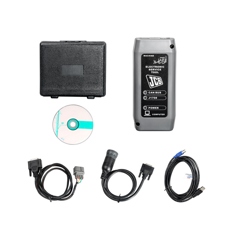
JCB Product Support Laptop Based Diagnostic Tool Manual Download
JCB Diagnostic Trouble Codes Download
JCB flash codes list Download
JCB JS-Excavator’s Fault Codes List Download
JCB v8+ Electrical Error Fault codes v1-07 Download
Troubleshooting/fault code,error kode JCB Excavator JS 200 JS 210 JS 220 JS 240 JS 260 Download
Livelink is a monitoring system that allows you to check the condition of equipment from anywhere in the world.
A special adapter connects to the equipment and transmits data to the JCB site via satellites and the cellular network, so that at any time, wherever you are, you can go to the site and find out
the current state of the observed JCB equipment.
In the GENERAL category, you can view help information, DLA adapter settings, Servicemaster program manual, as well as additional programs for diagnostics of
engines, transmissions and hydrostatic systems of such machines as FASTRAC T4 tractors, TELETRUK LPG loaders, Loadall 532H-537H telehandlers.
In order to start diagnostics or other procedures, you need to select the type of equipment from the corresponding category.
And then select the desired procedure from the available ones. For most types of equipment, in addition to diagnostics, you can configure the blocks, download new firmware and updates, view the
service history, decode error codes, do various tests, detailed help is also available in which you can see the location of components and wiring diagrams.
Please note that the list of available options for different types and models of equipment is different!
JCB Diagnostic Kit (DLA) is a multifunctional dealer scanner that reads diagnostic trouble codes, ranking them according to the degree of need for service on JCB equipment.
Main functional features:
reads fault codes and ranks them in order of importance.
calibrates, parameters and programs ECM units.
carries out a reset of service intervals.
Compatible with Jcb Service Master 2 software.
works with CAN protocol in OBD II system.
supplied with instructions for operation, repair and diagnostics of JCB equipment and engines Isuzu, Deutz, Cummins.
JCB Diagnostic Kit (DLA) Applicability
JCB agricultural machinery
Fastrac tractors (2000-3000, 3000 2 Series, 3000 Series 3, 7000-Series, 8250-Series 1, 8250 3 Series, 8000-Series 3).
Telescopic handlers (2007 -, 2007 +).
Wheeled backhoe loaders (Large, Large 2012+, Compact).
JC construction machinery
Backhoe loaders, tracked excavators (JS / JZ, JZ70).
Wheeled excavators, compact excavators (Mini / Midi) (801-8065, 8080-8085).
Telescopic handlers (2007 -, 2007 +).
Skidsteer loaders (Robot and others).
Telescopic handlers Teletrucks.
Wheeled backhoe loaders (Large, Large 2012+, Compact).
Frontal loaders.
Vibrating rollers.
Rough terrain forklifts.
JCB engines
JCB Dieselmax (MPS, OEM Base, G Drive).
JCB Ecomax (MPS, OEM Base, G Drive).
Equipment
JCB Diagnostic Kit (DLA) scanner.
USB cable.
DB9 cable.
9-pin adapter for German equipment.
8-pin cable.
JCB ServiceMaster 2 v10.3.1 software.
JCB Compact Service Manuals v50 [2011] (S1, S2, S3, S4, S5).
|
Tracked & Wheeled Excavators |
Extracted fromVersion 145 |
No of Error Codes in list 978 |
|
J1939 |
In Use? |
Reviewed/ |
Diagnostic Trouble |
Machine Reaction |
Extended Fault Text (Datalogger/Diagnostic Tools) |
|
0x00 |
Y |
55 |
P0001 |
Torque Reduction |
IMV driver fault is detected |
|
0x00 |
Y |
55 |
P0002 |
Torque Reduction |
Rail Pressure Negative Control Error During ‘IMV-Only’ control. PID controller not able to stabilise the |
|
0x00 |
Y |
55 |
P0002 |
Torque Reduction |
Rail pressure control error (pressure error too high). |
|
0x00 |
Y |
55 |
P0002 |
Delayed Engine Stop |
Rail Pressure Positive Control Error During ‘IMV-Only’ control. PID controller not able to stabilise the |
|
0x00 |
Y |
55 |
P0002 |
Torque Reduction |
Rail pressure control error (pressure error too low). |
|
0x00 |
Y |
55 |
P0003 |
Rail pressure control feedback low error |
|
|
0x00 |
Y |
55 |
P0003 |
Torque Reduction |
IMV driver fault is detected |
|
0x00 |
Y |
55 |
P0004 |
Torque Reduction |
IMV driver fault is detected |
|
0x00 |
Y |
55 |
P0004 |
Torque Reduction |
Rail pressure control feedback high error |
|
0x00 |
Y |
124 |
P0016 |
Cam Sensor Phase Shift |
|
|
0x00 |
Y |
124 |
P0045 |
VNT Control Fault |
|
|
0x00 |
Y |
124 |
P0045 |
Turbo EVRV Fault |
|
|
0x3D |
Y |
114 |
P0070-81 |
CAN bus message error from engine ECU |
|
|
0x3D |
Y |
114 |
P0070-87 |
CAN bus message error from engine ECU |
|
|
0x3D |
Y |
114 |
P0071-87 |
CAN bus message error for environment temperature from engine ECU |
|
|
0x00 |
Y |
55 |
P007A |
Torque Reduction |
TMAP (Intake Manifold 1 temp) Temperature Element sensor fault (ADC) |
|
0x00 |
Y |
55 |
P007C |
Torque Reduction |
TMAP (Intake Manifold 1 temp) Temperature Element sensor low fault |
|
0x00 |
Y |
55 |
P007D |
Torque Reduction |
TMAP (Intake Manifold 1 temp) Temperature Element sensor high fault |
|
0x00 |
Y |
55 |
P007E |
Torque Reduction |
TMAP (Intake Manifold 1 temp) Temperature Element sensor noise fault |
|
0x00 |
Y |
114 |
P0087 |
Torque Reduction |
Rail Pressure Control Error Positive |
|
0x00 |
Y |
55 |
P0087 |
Rail Pressure build low fault |
|
|
0x00 |
Y |
114 |
P0087 |
Rail Pressure build normal fault |
|
|
0x00 |
Y |
114 |
P0087 |
Torque Reduction_Delayed Engine Stop |
RPC Variable Limit Capacity (VLC) Torque reduction clamped |
|
0x00 |
Y |
124 |
P0087 |
Torque Reduction_Delayed Engine Stop |
Pressure Limiter Open |
|
0x00 |
Y |
114 |
P0087 |
Torque Reduction |
RPC Variable Limit Capacity (VLC) Torque reduction above its threshold |
|
0x00 |
Y |
114 |
P0088 |
Torque Reduction |
Rail pressure control error during HPV control (over max calibrated system pressure) |
|
0x00 |
Y |
114 |
P0088 |
Torque Reduction |
Rail pressure control error during IMV control (over max calibrated system pressure) |
|
0x00 |
Y |
55 |
P0088 |
Torque Reduction |
Rail pressure control undefined error (over max calibrated system pressure) |
|
0x00 |
Y |
114 |
P0088 |
Rail Pressure Control Error Negative |
|
|
0x00 |
Y |
124 |
P0088 |
Torque Reduction |
C/Rail pressure exceeds hi upper limit3 |
|
0x00 |
Y |
114 |
P0088 |
Rail Pressure overpressure timeout |
|
|
0x00 |
Y |
124 |
P0088 |
Torque Reduction |
Common Rail Pressure Rise㸦 1st Stage㸧 |
|
0x00 |
Y |
114 |
P0089 |
Rail Pressure control error |
|
|
0x00 |
Y |
114 |
P0089 |
Rail Pressure Negative Control Error During ‘HPV-Only’ control. PID controller not able to stabilise the |
|
0x00 |
Y |
114 |
P0089 |
Rail Pressure Positive Control Error During ‘HPV-Only’ control. PID controller not able to stabilise the |
|
|
0x00 |
Y |
55 |
P0089 |
Rail Pressure Negative Control Error During ‘IC & HMV’ control. PID controller not able to stabilise the |
|
|
0x00 |
Y |
114 |
P0089 |
Rail Pressure Positive Control Error During ‘IC & HMV’ control. PID controller not able to stabilise the |
|
|
0x00 |
Y |
114 |
P0089 |
Torque Reduction |
Rail Pressure Negative Control Error During ‘RVD-Only’ control. PID controller not able to stabilise the |
|
0x00 |
Y |
114 |
P0089 |
Delayed Engine Stop |
Rail Pressure Positive Control Error During ‘RVD-Only’ control. PID controller not able to stabilise the |
|
0x00 |
Y |
114 |
P0089 |
Torque Reduction |
Check that HPV is not stuck during IMV regulation. |
|
0x00 |
Y |
114 |
P0089 |
Torque Reduction |
HPV open loop slope fault detected |
|
0x00 |
Y |
124 |
P0089 |
Common Rail Pressure Fault (Excess Feed) |
|
|
0x00 |
Y |
55 |
P0090 |
Torque Reduction |
HPV driver in ECU fault detected |
|
0x00 |
Y |
55 |
P0091 |
Torque Reduction |
Check HPV regulation control trim low |
|
0x00 |
Y |
114 |
P0091 |
Torque Reduction |
Check HPV hardware current control trim low |
|
0x00 |
Y |
114 |
P0091 |
Torque Reduction |
HPV current feedback low fault detected |
|
0x00 |
Y |
124 |
P0091 |
Torque Reduction |
SCV Low Voltage Fault |
|
0x00 |
Y |
114 |
P0091 |
Torque Reduction |
HPV driver in ECU fault detected |
|
0x00 |
Y |
55 |
P0092 |
Torque Reduction |
Check HPV regulation control trim high. |
|
0x00 |
Y |
124 |
P0092 |
Torque Reduction_Delayed Engine Stop |
SCV High Voltage Fault |
|
0x00 |
Y |
114 |
P0092 |
Torque Reduction |
Check HPV hardware current control trim high |
|
0x00 |
Y |
114 |
P0092 |
Torque Reduction_Delayed Engine Stop |
HPV current feedback high fault detected |
|
0x00 |
Y |
114 |
P0092 |
Torque Reduction_Delayed Engine Stop |
HPV driver in ECU fault detected |
|
0x00 |
Y |
124 |
P0093 |
Common Rail Pressure Fall (No Feed) |
|
|
0x00 |
Y |
124 |
P0093 |
Common Rail Pressure Fault (Lack of Feed 2) |
|
|
0x00 |
Y |
55 |
P0095 |
Torque Reduction |
Intake manifold temperature (M2) signal sensor ADC fault (Intake Manifold 2 temp) |
|
0x00 |
Y |
55 |
P0096 |
Torque Reduction |
Intake manifold temperature sensor (M2) signal noise fault (Intake Manifold 2 temp) |
|
0x00 |
Y |
55 |
P0096 |
Torque Reduction |
Intake manifold temperature sensor (M2) signal plausibility fault (Intake Manifold 2 temp) |
|
0x00 |
Y |
55 |
P0097 |
Torque Reduction |
Intake manifold temperature sensor (M2) signal low fault (Intake Manifold 2 temp) |
|
0x00 |
Y |
55 |
P0098 |
Torque Reduction |
Intake manifold temperature sensor (M2) signal high signal fault (Intake Manifold 2 temp) |
|
0x3D |
Y |
114 |
P00B7-87 |
T4F Inducement |
CAN bus message error for coolant sensor from engine ECU |
|
0x00 |
Y |
55 |
P0100 |
Torque Reduction |
AMF High Side Driver fault Short Circuit To Ground (SC2G) |
|
0x00 |
Y |
114 |
P0100 |
Torque Reduction |
AMF fault (global). Set if plau, grad or electrical flt is present |
|
0x00 |
Y |
114 |
P0100 |
Torque Reduction |
AMF High Side Driver fault (Global |
|
0x00 |
Y |
114 |
P0100 |
Torque Reduction |
AMF High Side Driver fault Open Circuit (OC) Or Short Circuit to Battery (SC2VBAT) |
|
0x00 |
Y |
114 |
P0100 |
Torque Reduction |
AMF High Side Driver fault Short Circuit (SC) |
|
0x00 |
Y |
114 |
P0100 |
Torque Reduction |
AMF electrical sensor fault (ADC) |
|
0x00 |
Y |
124 |
P0101 |
MAF Sensor Fault |
|
|
0x00 |
Y |
124 |
P0102 |
Torque Reduction |
MAF Low Voltage Fault |
|
0x00 |
Y |
55 |
P0102 |
Torque Reduction |
AMF electrical sensor low fault |
|
0x00 |
Y |
124 |
P0103 |
Torque Reduction |
MAF High Voltage Fault |
|
0x00 |
Y |
55 |
P0103 |
Torque Reduction |
AMF electrical sensor high fault |
|
0x00 |
Y |
55 |
P0105 |
Torque Reduction |
Intake Manifold Absolute Pressure (MAP) sensor global fault |
|
0x00 |
Y |
55 |
P0106 |
Torque Reduction |
Intake Manifold Absolute Pressure (MAP) sensor signal drift low fault |
|
0x00 |
Y |
55 |
P0106 |
Torque Reduction |
Intake Manifold Absolute Pressure (MAP) sensor signal drift high fault |
|
0x00 |
Y |
55 |
P0106 |
Torque Reduction |
Intake Manifold Absolute Pressure (MAP) sensor signal plausibility fault |
|
0x00 |
Y |
55 |
P0106 |
Torque Reduction |
Intake Manifold Absolute Pressure (MAP) sensor signal plausibility high fault |
|
0x00 |
Y |
55 |
P0106 |
Torque Reduction |
Intake Manifold Absolute Pressure (MAP) sensor signal plausibility low fault |
|
0x00 |
Y |
124 |
P0107 |
Boost Pressure Sensor Fault 㸦 Low Voltage Fault |
|
|
0x00 |
Y |
124 |
P0108 |
Boost Pressure Sensor Fault 㸦 High Voltage Fault㸧 |
|
|
0x00 |
Y |
55 |
P0110 |
Torque Reduction |
Inlet Air Temperature (IAT) sensor signal ADC fault detected |
|
0x00 |
Y |
124 |
P0112 |
Torque Reduction |
Inlet Air Temperature (IAT) sensor signal low fault detected |
|
0x00 |
Y |
124 |
P0113 |
Torque Reduction |
Inlet Air Temperature (IAT) sensor signal high fault detected |
|
0x00 |
Y |
55 |
P0115 |
Torque Reduction |
Coolant sensor signal fault |
|
0x00 |
Y |
55 |
P0116 |
Coolant sensor fault (plausibility) |
|
|
0x00 |
Y |
124 |
P0116 |
Torque Reduction |
Coolant temperature sensor performance invalid |
|
0x00 |
Y |
55 |
P0117 |
Coolant sensor signal low fault |
|
|
0x00 |
Y |
124 |
P0117 |
Coolant temperature sensor signal too low |
|
|
0x00 |
Y |
124 |
P0118 |
Coolant sensor signal high fault |
|
|
0x00 |
Y |
124 |
P0122 |
Intake Throttle Position Low Voltage Fault |
|
|
0x00 |
Y |
124 |
P0123 |
Intake Throttle Position High Voltage Fault |
|
|
0x3D |
Y |
114 |
P0129-87 |
Erroneous signal for Barometric Pressure. |
|
|
0x3D |
Y |
114 |
P0129-87 |
CAN bus message error for environment pressure from engine ECU |
|
|
0x00 |
Y |
55 |
P0133 |
Wide Range Air Fuel control (WRAF) fault: Response |
|
|
0x00 |
Y |
55 |
P0180 |
Torque Reduction |
Fuel temperature ADC fault |
|
J1939 |
In Use? |
Added |
Diagnostic Trouble |
Machine Reaction |
Extended Fault Text (Datalogger/Diagnostic Tools) |
|
0x00 |
Y |
124 |
P0181 |
Torque Reduction |
Fuel Temperature Sensor Fault |
|
0x00 |
Y |
55 |
P0181 |
Torque Reduction |
Fuel temperature sensor gradient fault |
|
0x3D |
Y |
114 |
P0181-87 |
CAN bus message error for fuel temperature from engine ECU |
|
|
0x00 |
Y |
124 |
P0182 |
Torque Reduction |
Fuel temperature sensor low fault |
|
0x00 |
Y |
124 |
P0183 |
Torque Reduction |
Fuel temperature sensor high fault |
|
0x00 |
Y |
55 |
P0190 |
Torque Reduction_Limp Home (Idle Only) |
Rail Pressure Sensor signal grad fault |
|
0x00 |
Y |
55 |
P0191 |
Torque Reduction_Limp Home (Idle Only) |
Rail Pressure Sensor fault. Above maximum threshold (out of range at key-on) |
|
0x00 |
Y |
55 |
P0191 |
Torque Reduction_Limp Home (Idle Only) |
Rail Pressure Sensor fault. Below minimum threshold (out of range at key-on) |
|
0x00 |
Y |
55 |
P0191 |
Torque Reduction_Limp Home (Idle Only) |
Rail Pressure Sensor fault. Exceeds threshold (out of range at key-on) |
|
0x00 |
Y |
124 |
P0192 |
Torque Reduction_Limp Home (Idle Only) |
Rail Pressure Sensor signal low fault |
|
0x00 |
Y |
124 |
P0193 |
Torque Reduction_Limp Home (Idle Only) |
Rail Pressure Sensor signal high fault |
|
0x00 |
Y |
55 |
P0194 |
Torque Reduction_Limp Home (Idle Only)_Delayed |
Rail Pressure Sensor signal drop fault |
|
0x00 |
Y |
55 |
P0195 |
Torque Reduction |
Oil temperature sensor signal global fault |
|
0x00 |
Y |
114 |
P0195 |
Torque Reduction |
Oil temperature sensor signal external voltage (V-Ref) fault |
|
0x00 |
Y |
55 |
P0196 |
Torque Reduction |
Oil temperature sensor signal plausability fault |
|
0x00 |
Y |
55 |
P0196 |
Torque Reduction |
Oil temperature sensor signal gradient fault |
|
0x3D |
Y |
114 |
P0196-87 |
CAN bus message error for oil temperature from engine ECU |
|
|
0x00 |
Y |
55 |
P0197 |
Torque Reduction |
Oil temperature sensor signal low fault |
|
0x00 |
Y |
55 |
P0198 |
Torque Reduction |
Oil temperature sensor signal high fault |
|
0x00 |
Y |
55 |
P0201 |
Injector 2 Open Circuit fault (OC) |
|
|
0x00 |
Y |
55 |
P0201 |
Injector in Cylinder 1 Short Circuit HSD to LSD |
|
|
0x00 |
Y |
124 |
P0201 |
Injector in Cylinder 1 Open Circuit fault (OC) |
|
|
0x00 |
Y |
124 |
P0202 |
Injector 1 Open Circuit fault (OC) |
|
|
0x00 |
Y |
55 |
P0202 |
Injector in Cylinder 2 Short Circuit HSD to LSD |
|
|
0x00 |
Y |
88 |
P0202 |
Injector in Cylinder 2 Open Circuit fault (OC) |
|
|
0x00 |
Y |
124 |
P0203 |
Injector 3 Open Circuit fault (OC) |
|
|
0x00 |
Y |
55 |
P0203 |
Injector in Cylinder 3 Short Circuit HSD to LSD |
|
|
0x00 |
Y |
88 |
P0203 |
Injector in Cylinder 3 Open Circuit fault (OC) |
|
|
0x00 |
Y |
124 |
P0204 |
Injector 0 Open Circuit fault (OC) |
|
|
0x00 |
Y |
55 |
P0204 |
Injector in Cylinder 4 Short Circuit HSD to LSD |
|
|
0x00 |
Y |
88 |
P0204 |
Injector in Cylinder 4 Open Circuit fault (OC) |
|
|
0x00 |
Y |
124 |
P0205 |
Injector in Cylinder 5 Open Circuit fault (OC) |
|
|
0x00 |
Y |
88 |
P0205 |
Injector in Cylinder 5 Short Circuit HSD to LSD |
|
|
0x00 |
Y |
124 |
P0206 |
Injector in Cylinder 6 Open Circuit fault (OC) |
|
|
0x00 |
Y |
88 |
P0206 |
Injector in Cylinder 6 Short Circuit HSD to LSD |
|
|
0x00 |
Y |
124 |
P0217 |
Torque Reduction |
Coolant temperature exceeds upper limit |
|
0x00 |
Y |
124 |
P0219 |
Torque Reduction |
Engine overspeed condition |
|
0x00 |
Y |
124 |
P0234 |
Torque Reduction |
Turbo Over Boost |
|
0x00 |
Y |
55 |
P0235 |
Torque Reduction |
Boosted air pressure sensor fault: ADC |
|
0x00 |
Y |
55 |
P0237 |
Torque Reduction |
Boosted air pressure sensor low fault |
|
0x00 |
Y |
55 |
P0238 |
Torque Reduction |
Boosted air pressure sensor high fault |
|
0x00 |
Y |
55 |
P0252 |
Torque Reduction |
Rail pressure control error (IMV current trim drift). |
|
0x00 |
Y |
114 |
P0252 |
Torque Reduction |
Rail pressure control error (IMV current trim drift). |
|
0x00 |
Y |
114 |
P0252 |
Torque Reduction |
Rail pressure control error (IMV current trim drift). |
|
0x00 |
Y |
114 |
P0252 |
Torque Reduction |
Rail pressure control error (IMV current trim drift). |
|
0x00 |
Y |
114 |
P0252 |
Torque Reduction |
Rail pressure control error (IMV current trim drift). |
|
0x00 |
Y |
55 |
P0253 |
Torque Reduction_Delayed Engine Stop |
Rail pressure control by the IMV. Occurs at high fuel delivery for low (negative) current trim |
|
0x00 |
Y |
55 |
P0254 |
Torque Reduction_Delayed Engine Stop |
Rail pressure control fault by the IMV. Occurs at high fuel delivery for high (positive) current trim |
|
0x00 |
Y |
55 |
P0261 |
Torque Reduction |
Injector and wiring harness resistance too high/low (inj 2) |
|
0x00 |
Y |
55 |
P0261 |
Torque Reduction |
Injector and wiring harness resistance too high/low (inj 2) |
|
0x00 |
Y |
55 |
P0262 |
Torque Reduction |
Injector and wiring harness resistance drop (Inj 2) |
|
0x00 |
Y |
55 |
P0262 |
Torque Reduction |
Injector and wiring harness resistance drop (Inj 2) |
|
0x00 |
Y |
55 |
P0263 |
Torque Reduction |
Cylinder balancing fault injector 2 stuck closed |
|
0x00 |
Y |
55 |
P0264 |
Torque Reduction |
Injector and wiring harness resistance too high/low (inj 1) |
|
0x00 |
Y |
55 |
P0264 |
Torque Reduction |
Injector and wiring harness resistance too high/low (inj 1) |
|
0x00 |
Y |
55 |
P0265 |
Torque Reduction |
Injector and wiring harness resistance drop (Inj 1) |
|
0x00 |
Y |
55 |
P0265 |
Torque Reduction |
Injector and wiring harness resistance drop (Inj 1) |
|
0x00 |
Y |
55 |
P0266 |
Torque Reduction |
Cylinder balancing fault injector 1 stuck closed |
|
0x00 |
Y |
55 |
P0267 |
Torque Reduction |
Injector and wiring harness resistance too high/low (inj 3) |
|
0x00 |
Y |
55 |
P0267 |
Torque Reduction |
Injector and wiring harness resistance too high/low (inj 3) |
|
0x00 |
Y |
55 |
P0268 |
Torque Reduction |
Injector and wiring harness resistance drop (Inj 3) |
|
0x00 |
Y |
55 |
P0268 |
Torque Reduction |
Injector and wiring harness resistance drop (Inj 3) |
|
0x00 |
Y |
55 |
P0269 |
Torque Reduction |
Cylinder balancing fault injector 3 stuck closed |
|
0x00 |
Y |
55 |
P0270 |
Torque Reduction |
Injector drift fault detection on Injector 2. Fault which is set when the Injector 2 MDP trim exceeds the |
|
0x00 |
Y |
55 |
P0270 |
Torque Reduction |
Injector drift fault detection on Injector 2. Fault which is set when Injector 2 MDP trim exceeds the |
|
0x00 |
Y |
55 |
P0271 |
Torque Reduction |
Injector and wiring harness resistance drop (Inj 0) |
|
0x00 |
Y |
55 |
P0271 |
Torque Reduction |
Injector and wiring harness resistance drop (Inj 0) |
|
0x00 |
Y |
55 |
P0272 |
Torque Reduction |
Cylinder balancing fault injector 0 stuck closed |
|
0x00 |
Y |
88 |
P0273 |
Injector and wiring harness resistance too high/low (inj 1) |
|
|
0x00 |
Y |
88 |
P0273 |
Injector and wiring harness resistance too high/low (inj 1) |
|
|
0x00 |
Y |
88 |
P0274 |
Injector and wiring harness resistance drop (Inj 1) |
|
|
0x00 |
Y |
88 |
P0274 |
Injector and wiring harness resistance drop (Inj 1) |
|
|
0x00 |
Y |
88 |
P0275 |
Cylinder balancing fault injector 1 stuck closed |
|
|
0x00 |
Y |
88 |
P0276 |
Injector and wiring harness resistance too high/low (inj 3) |
|
|
0x00 |
Y |
88 |
P0276 |
Injector and wiring harness resistance too high/low (inj 3) |
|
|
0x00 |
Y |
88 |
P0277 |
Injector and wiring harness resistance drop (Inj 3) |
|
|
0x00 |
Y |
88 |
P0277 |
Injector and wiring harness resistance drop (Inj 3) |
|
|
0x00 |
Y |
88 |
P0278 |
Cylinder balancing fault injector 3 stuck closed |
|
|
0x00 |
Y |
124 |
P0299 |
Torque Reduction |
Turbo Low Boost |
|
0x00 |
Y |
55 |
P029A |
Injector drift fault detection on Injector 3. Fault which is set when the Injector 3 MDP trim exceeds the |
|
|
0x00 |
Y |
55 |
P029A |
Injector drift fault detection on Injector 2. Fault which is set when the Injector 2 MDP trim exceeds the |
|
|
0x00 |
Y |
55 |
P029A |
Injector drift fault detection on Injector 2. Fault which is set when Injector 2 MDP trim exceeds the |
|
|
0x00 |
Y |
55 |
P029B |
Fault which is set when the Injector 3 absolute MDP value is below a calibrated threshold |
|
|
0x00 |
Y |
55 |
P029B |
Injector drift fault detection on Injector 2. Fault which is set when Injector 2 MDP trim exceeds the |
|
|
0x00 |
Y |
55 |
P029B |
Injector drift fault detection on Injector 2. Fault which is set when Injector 2 MDP trim exceeds the |
|
|
0x00 |
Y |
55 |
P029B |
Injector drift fault detection on Injector 2. Fault which is set when Injector 2 MDP trim exceeds the |
|
J1939 |
In Use? |
Added |
Diagnostic Trouble |
Machine Reaction |
Extended Fault Text (Datalogger/Diagnostic Tools) |
|
0x00 |
Y |
55 |
P029E |
Injector drift fault detection on Injector 1. Fault which is set when the Injector 1 MDP trim exceeds the |
|
|
0x00 |
Y |
55 |
P029E |
Injector drift fault detection on Injector 1. Fault which is set when the Injector 1 MDP trim exceeds the |
|
|
0x00 |
Y |
55 |
P029E |
Injector drift fault detection on Injector 1. Fault which is set when Injector 1 MDP trim exceeds the |
|
|
0x00 |
Y |
55 |
P029F |
Fault which is set when the Injector 2 absolute MDP value is below a calibrated threshold |
|
|
0x00 |
Y |
55 |
P029F |
Injector drift fault detection on Injector 1. Fault which is set when Injector 1 MDP trim exceeds the |
|
|
0x00 |
Y |
55 |
P029F |
Injector drift fault detection on Injector 1. Fault which is set when Injector 1 MDP trim exceeds the |
|
|
0x00 |
Y |
55 |
P029F |
Injector drift fault detection on Injector 1. Fault which is set when Injector 1 MDP trim exceeds the |
|
|
0x00 |
Y |
55 |
P02A2 |
Injector drift fault detection on Injector 2. Fault which is set when the Injector 2 MDP trim exceeds the |
|
|
0x00 |
Y |
55 |
P02A2 |
Injector drift fault detection on Injector 2. Fault which is set when the Injector 2 MDP trim exceeds the |
|
|
0x00 |
Y |
55 |
P02A2 |
Injector drift fault detection on Injector 2. Fault which is set when Injector 2 MDP trim exceeds the |
|
|
0x00 |
Y |
55 |
P02A3 |
Fault which is set when the Injector 4 absolute MDP value is below a calibrated threshold |
|
|
0x00 |
Y |
55 |
P02A3 |
Injector drift fault detection on Injector 3. Fault which is set when Injector 3 MDP trim exceeds the |
|
|
0x00 |
Y |
55 |
P02A3 |
Injector drift fault detection on Injector 3. Fault which is set when Injector 3 MDP trim exceeds the |
|
|
0x00 |
Y |
55 |
P02A3 |
Injector drift fault detection on Injector 3. Fault which is set when Injector 3 MDP trim exceeds the |
|
|
0x00 |
Y |
55 |
P02A6 |
Injector drift fault detection on Injector 0. Fault which is set when the Injector 0 MDP trim exceeds the |
|
|
0x00 |
Y |
55 |
P02A6 |
Injector drift fault detection on Injector 0. Fault which is set when the Injector 0 MDP trim exceeds the |
|
|
0x00 |
Y |
55 |
P02A6 |
Injector drift fault detection on Injector 0. Fault which is set when Injector 0 MDP trim exceeds the |
|
|
0x00 |
Y |
55 |
P02A7 |
Fault which is set when the Injector 1 absolute MDP value is below a calibrated threshold |
|
|
0x00 |
Y |
55 |
P02A7 |
Injector drift fault detection on Injector 0. Fault which is set when Injector 0 MDP trim exceeds the |
|
|
0x00 |
Y |
55 |
P02A7 |
Injector drift fault detection on Injector 0. Fault which is set when Injector 0 MDP trim exceeds the |
|
|
0x00 |
Y |
55 |
P02A7 |
Injector drift fault detection on Injector 0. Fault which is set when Injector 0 MDP trim exceeds the |
|
|
0x00 |
Y |
88 |
P02AA |
Injector drift fault detection on Injector 1. Fault which is set when the Injector 1 MDP trim exceeds the |
|
|
0x00 |
Y |
88 |
P02AA |
Injector drift fault detection on Injector 1. Fault which is set when the Injector 1 MDP trim exceeds the |
|
|
0x00 |
Y |
88 |
P02AA |
Injector drift fault detection on Injector 1. Fault which is set when Injector 1 MDP trim exceeds the |
|
|
0x00 |
Y |
88 |
P02AB |
Fault which is set when the Injector 1 absolute MDP value is below a calibrated threshold |
|
|
0x00 |
Y |
88 |
P02AB |
Injector drift fault detection on Injector 1. Fault which is set when Injector 1 MDP trim exceeds the |
|
|
0x00 |
Y |
88 |
P02AB |
Injector drift fault detection on Injector 1. Fault which is set when Injector 1 MDP trim exceeds the |
|
|
0x00 |
Y |
88 |
P02AB |
Injector drift fault detection on Injector 1. Fault which is set when Injector 1 MDP trim exceeds the |
|
|
0x00 |
Y |
88 |
P02AE |
Injector drift fault detection on Injector 3. Fault which is set when the Injector 3 MDP trim exceeds the |
|
|
0x00 |
Y |
88 |
P02AE |
Injector drift fault detection on Injector 3. Fault which is set when the Injector 3 MDP trim exceeds the |
|
|
0x00 |
Y |
88 |
P02AE |
Injector drift fault detection on Injector 3. Fault which is set when Injector 3 MDP trim exceeds the |
|
|
0x00 |
Y |
88 |
P02AF |
Fault which is set when the Injector 3 absolute MDP value is below a calibrated threshold |
|
|
0x00 |
Y |
88 |
P02AF |
Injector drift fault detection on Injector 3. Fault which is set when Injector 3 MDP trim exceeds the |
|
|
0x00 |
Y |
88 |
P02AF |
Injector drift fault detection on Injector 3. Fault which is set when Injector 3 MDP trim exceeds the |
|
|
0x00 |
Y |
88 |
P02AF |
Injector drift fault detection on Injector 3. Fault which is set when Injector 3 MDP trim exceeds the |
|
|
0x3D |
Y |
114 |
P0321-87 |
CAN bus message error for engine speed from engine ECU |
|
|
0x00 |
Y |
55 |
P0325 |
Accelerometer fault (signal/noise ratio too low in idle) |
|
|
0x00 |
Y |
94 |
P0330 |
Knock Sensor 1 Circuit |
|
|
0x00 |
Y |
124 |
P0335 |
Crank Sensor Fault 㸦 No Signal㸧 |
|
|
0x00 |
Y |
55 |
P0335 |
Crankshaft Position Sensor «A» Circuit |
|
|
0x00 |
Y |
114 |
P0335 |
Crank signal overspeed fault |
|
|
0x00 |
Y |
124 |
P0336 |
Torque Reduction |
Crank Sensor Fault 㸦 Signal Fault㸧 |
|
0x00 |
Y |
55 |
P0340 |
Torque Reduction |
Cam signal last learnt value is outside of limits |
|
0x00 |
Y |
124 |
P0340 |
Torque Reduction |
G Sensor Fault (No Signal) |
|
0x00 |
Y |
55 |
P0341 |
Torque Reduction |
Cam signal drift higher than threshold |
|
0x00 |
Y |
124 |
P0341 |
Torque Reduction |
G Sensor Fault (Abnormal Signal㸧 |
|
0x00 |
Y |
55 |
P0341 |
Camshaft Position Sensor A Circuit Range / Performance |
|
|
0x00 |
Y |
55 |
P0341 |
Torque Reduction |
Cam signal lost (no Cam signal seen in 2 Crank rotations) |
|
0x00 |
Y |
55 |
P0341 |
Torque Reduction |
Cam signal fault (missing event within the expected window) |
|
0x00 |
Y |
55 |
P0341 |
Cam signal fault (overspeed detected) |
|
|
0x3D |
Y |
114 |
P0350-02 |
Error monitoring for system protection based on ignition switch input |
|
|
0x00 |
Y |
55 |
P0371 |
Torque Reduction |
Crank signal is too close to the previous one |
|
0x00 |
Y |
55 |
P0372 |
Torque Reduction |
Elapsed time between CPS events is too high |
|
0x00 |
Y |
55 |
P0374 |
Torque Reduction |
Crank signal lost (no CPS signal seen in 1 Cam rotation) |
|
0x00 |
Y |
124 |
P0380 |
Glow Plug/Heater Circuit «A» |
|
|
0x00 |
Y |
55 |
P0380 |
Glow Plug/Heater Circuit «A» |
|
|
0x00 |
Y |
124 |
P0381 |
Glow Plug Fault |
|
|
0x00 |
Y |
55 |
P0383 |
Glow Plug Control Module Control Circuit Low |
|
|
0x00 |
Y |
55 |
P0384 |
Glow Plug Control Module Control Circuit High |
|
|
0x00 |
Y |
55 |
P0400 |
Torque Reduction / T4F Inducement |
EGR flow reached its limit |
|
0x00 |
Y |
124 |
P0401 |
EGR Gas flow Fault |
|
|
0x00 |
Y |
124 |
P0404 |
EGR Valve Control Fault |
|
|
0x00 |
Y |
124 |
P0404 |
EGR Open Defective |
|
|
0x00 |
Y |
94 |
P0404 |
Exhaust Gas Recirculation «A» Control Circuit Range/Performance |
|
|
0x00 |
Y |
55 |
P0405 |
Exhaust Gas Recirculation Sensor «A» Circuit Low |
|
|
0x00 |
Y |
55 |
P0406 |
Exhaust Gas Recirculation Sensor «A» Circuit High |
|
|
0x00 |
Y |
124 |
P0409 |
EGR Position Sensor Fault 㸦 Brushless Specification㸧 |
|
|
0x00 |
Y |
124 |
P041C |
Manifold Temperature Sensor Fault 㸦 High Voltage |
|
|
0x00 |
Y |
124 |
P041D |
Manifold Temperature Sensor Fault 㸦 Low Voltage Fault㸧 |
|
|
0x00 |
Y |
124 |
P0426 |
DPF Exhaust Temperature 1 High |
|
|
0x00 |
Y |
124 |
P0426 |
DPF Exhaust Temperature 1Low |
|
|
0x00 |
Y |
124 |
P0427 |
Exhaust Temperature Sensor 1Low Voltage Fault |
|
|
0x00 |
Y |
124 |
P0428 |
Exhaust Temperature Sensor 1High Voltage Fault |
|
|
0x00 |
Y |
124 |
P042B |
DPF Exhaust Temperature 2 High |
|
|
0x00 |
Y |
124 |
P042B |
DPF Exhaust Temperature 2 Low |
|
|
0x00 |
Y |
124 |
P042C |
Exhaust Temperature Sensor 2 Low Voltage Fault |
|
|
0x00 |
Y |
124 |
P042D |
Exhaust Temperature Sensor 2 High Voltage Fault |
|
|
0x00 |
Y |
94 |
P046D |
Exhaust Gas Recirculation Sensor «A» Circuit Intermittent/Erratic |
|
|
0x00 |
Y |
55 |
P0470 |
Torque Reduction |
Exhaust manifold pressure (P3) signal ADC fault |
|
0x00 |
Y |
55 |
P0472 |
Torque Reduction |
Exhaust manifold pressure (P3) signal low fault |
|
0x00 |
Y |
55 |
P0472 |
Torque Reduction |
Exhaust manifold pressure (P3) signal drifted low |
|
0x00 |
Y |
55 |
P0473 |
Torque Reduction |
Exhaust manifold pressure (P3) signal high fault |
|
0x00 |
Y |
55 |
P0473 |
Torque Reduction |
Exhaust manifold pressure (P3) signal drifted high |
|
0x00 |
Y |
124 |
P0512 |
Starter Switch Fault |
|
|
0x00 |
Y |
55 |
P0520 |
Low oil pressure Lamp/Gauge drive open circuit (OC) |
|
|
0x00 |
Y |
55 |
P0520 |
Low oil pressure Lamp/Gauge drive short circuit (SC) |
|
|
0x00 |
Y |
55 |
P0520 |
Low oil pressure Lamp/Gauge drive short circuit to ground (SC2GND) |
|
|
0x00 |
Y |
55 |
P0520 |
Low oil pressure Lamp/Gauge drive short circuit to battery voltage (SC2VBATT) |
|
|
0x00 |
Y |
55 |
P0521 |
Oil pressure sensor signal global fault |
|
|
0x00 |
Y |
124 |
P0522 |
None |
Engine Oil Pressure Sensor Fault (Low Voltage Fault) |
|
0x00 |
Y |
88 |
P0522 |
Torque Reduction |
Oil Pressure Signal Out of Range High |
|
0x00 |
Y |
55 |
P0522 |
High Oil Pressure During Engine Running |
|
|
0x00 |
Y |
55 |
P0523 |
Low Oil Pressure During Engine Running |
|
|
0x27 |
Y |
91 |
P0523 |
Low Oil Pressure During Engine Running |
|
|
0x00 |
Y |
124 |
P0523 |
Engine Oil Pressure Sensor Fault (High Voltage Fault) |
|
|
0x00 |
Y |
88 |
P0523 |
Torque Reduction |
Oil Pressure Signal Out of Range Low |
|
0x00 |
Y |
88 |
P0523 |
Low Oil Pressure During Engine Running |
|
|
0x00 |
Y |
55 |
P0544 |
Torque Reduction |
Turbo in temperature fault |
|
0x00 |
Y |
55 |
P0545 |
Torque Reduction |
Turbo in temperature count low fault |
|
0x00 |
Y |
55 |
P0546 |
Torque Reduction |
Turbo in temperature count high fault |
|
0x00 |
Y |
124 |
P0560 |
12V Power Supply Voltage Fault |
|
|
0x00 |
Y |
55 |
P0562 |
Torque Reduction |
Battery voltage monitoring signal low fault |
|
0x00 |
Y |
124 |
P0562 |
Torque Reduction |
System Power Supply Low Voltage Fault |
|
0x3D |
Y |
114 |
P0562-16 |
Low battery voltage |
|
|
0x3D |
Y |
114 |
P0562-02 |
Fault due to low or high battery voltage supply to DCU |
|
|
0x00 |
Y |
55 |
P0563 |
Torque Reduction |
Battery voltage monitoring signal high fault |
|
0x00 |
Y |
124 |
P0563 |
Torque Reduction |
System Power Supply High Voltage Fault |
|
0x3D |
Y |
114 |
P0563-17 |
High battery voltage |
|
|
0x00 |
Y |
124 |
P0601 |
Torque Reduction |
ROM Fault |
|
0x00 |
Y |
124 |
P0602 |
Limp Home (Idle Only) |
QR Code Error |
|
0x00 |
Y |
114 |
P0602 |
Limp Home (Idle Only) |
C2I data not programmed |
|
0x00 |
Y |
55 |
P0602 |
Limp Home (Idle Only) |
C2I data not programmed |
|
0x00 |
Y |
114 |
P0602 |
Limp Home (Idle Only) |
C2I data not programmed |
|
0x00 |
Y |
114 |
P0602 |
Limp Home (Idle Only) |
C2I data not programmed |
|
0x00 |
Y |
114 |
P0602 |
Limp Home (Idle Only)_Engine Stop |
RAM corruption affecting Injector C2I data |
|
0x00 |
Y |
114 |
P0602 |
Functional Safety Fault |
|
|
0x00 |
Y |
55 |
P0602 |
Limp Home (Idle Only) |
Functional Safety Fault |
|
0x00 |
Y |
55 |
P0603 |
Engine Stop |
ECU memory integrity fault (data / cal integrity) |
|
0x00 |
Y |
55 |
P0604 |
Engine Stop |
ECU memory integrity fault (RAM integrity) |
|
0x00 |
Y |
124 |
P0604 |
Engine Stop |
RAM Fault |
|
0x00 |
Y |
55 |
P0605 |
Engine Stop |
ECU memory integrity fault (code integrity) |
|
0x00 |
Y |
55 |
P0606 |
Engine Stop |
Functional Safety Fault |
|
0x00 |
Y |
55 |
P0606 |
Engine Stop |
Functional Safety Fault |
|
0x00 |
Y |
55 |
P0606 |
Engine Stop |
Functional Safety Fault |
|
0x00 |
Y |
55 |
P0606 |
Engine Stop |
Functional Safety Fault |
|
0x00 |
Y |
55 |
P0606 |
Engine Stop |
Functional Safety Fault |
|
0x00 |
Y |
124 |
P0606 |
Engine Stop |
CPU Fault |
|
0x00 |
Y |
124 |
P0606 |
Engine Stop |
CPU Monitoring IC Fault |
|
0x00 |
Y |
55 |
P0606 |
Engine Stop |
Functional Safety Fault |
|
0x3D |
Y |
114 |
P0606-02 |
Peripheral monitoring error on DCU |
|
|
0x00 |
Y |
55 |
P0607 |
Engine Stop |
Functional Safety Fault |
|
0x00 |
Y |
55 |
P0607 |
Torque Reduction |
Throttle H-Bridge driver in ECU fault: Over temperature |
|
0x00 |
Y |
55 |
P060A |
Engine Stop |
Functional Safety Fault |
|
0x00 |
Y |
55 |
P060A |
Engine Stop |
Functional Safety Fault |
|
0x00 |
Y |
55 |
P060A |
Engine Stop |
Functional Safety Fault |
|
0x00 |
Y |
55 |
P060A |
Engine Stop |
Functional Safety Fault |
|
0x00 |
Y |
55 |
P060A |
Engine Stop |
Functional Safety Fault |
|
0x00 |
Y |
55 |
P060A |
Engine Stop |
Functional Safety Fault |
|
0x00 |
Y |
55 |
P060A |
Engine Stop |
Functional Safety Fault |
|
0x00 |
Y |
55 |
P060A |
Engine Stop |
Functional Safety Fault |
|
0x3D |
Y |
114 |
P060A-00 |
Monitoring error on DCU |
|
|
0x00 |
Y |
124 |
P060B |
A/D Conversion Fault |
|
|
0x00 |
Y |
55 |
P060B |
Limp Home (Idle Only)_Engine Stop |
ADC circuit fault (Global) |
|
0x00 |
Y |
55 |
P060B |
Torque Reduction |
HPV current feedback ADC fault detected |
|
0x00 |
Y |
55 |
P060B |
Internal Control Module A/D Processing Performance |
|
|
0x00 |
Y |
55 |
P060B |
Torque Reduction |
Functional Safety Fault |
|
SA (hex) |
In Use? |
Added |
Code |
Machine Reaction |
Extended Fault Text (Datalogger/Diagnostic Tools) |
|
0x00 |
Y |
55 |
P060B |
Torque Reduction |
Functional Safety Fault |
|
0x00 |
Y |
55 |
P060B |
Torque Reduction |
Functional Safety Fault |
|
0x00 |
Y |
55 |
P060C |
Engine Stop |
Functional Safety Fault |
|
0x00 |
Y |
55 |
P060C |
Engine Stop |
Functional Safety Fault |
|
0x00 |
Y |
55 |
P060C |
Engine Stop |
Functional Safety Fault |
|
0x00 |
Y |
55 |
P060C |
Engine Stop |
Functional Safety Fault |
|
0x00 |
Y |
55 |
P060C |
Engine Stop |
Functional Safety Fault |
|
0x00 |
Y |
55 |
P060C |
Engine Stop |
Functional Safety Fault |
|
0x00 |
Y |
55 |
P060C |
Engine Stop |
Functional Safety Fault |
|
0x00 |
Y |
55 |
P060C |
Engine Stop |
Functional Safety Fault |
|
0x00 |
Y |
55 |
P060C |
Engine Stop |
Functional Safety Fault |
|
0x3D |
Y |
114 |
P060C-00 |
DCU software reset performed |
|
|
0x3D |
Y |
114 |
P060C-41 |
T4F Inducement |
DCU software reset performed |
|
0x3D |
Y |
114 |
P060C-94 |
DCU software reset performed |
|
|
0x3D |
Y |
114 |
P060C-68 |
DCU software reset performed |
|
|
0x00 |
Y |
55 |
P060D |
Engine Stop |
Functional Safety Fault |
|
0x00 |
Y |
55 |
P060D |
Engine Stop |
Functional Safety Fault |
|
0x00 |
Y |
55 |
P060D |
Torque Reduction |
Functional Safety Fault |
|
0x00 |
Y |
55 |
P060D |
Torque Reduction |
Functional Safety Fault |
|
0x00 |
Y |
55 |
P060E |
Torque Reduction |
Functional Safety Fault |
|
0x00 |
Y |
55 |
P0612 |
Fuel Injector Control Module Relay Control |
|
|
0x00 |
Y |
55 |
P0612 |
Fuel Injector Control Module Relay Control |
|
|
0x00 |
Y |
55 |
P0612 |
Fuel Injector Control Module Relay Control |
|
|
0x00 |
Y |
55 |
P0612 |
Fuel Injector Control Module Relay Control |
|
|
0x00 |
Y |
124 |
P0615 |
Starter Relay Circuit |
|
|
0x00 |
Y |
55 |
P061A |
Functional Safety Fault |
|
|
0x00 |
Y |
55 |
P061B |
Torque Reduction |
Functional Safety Fault |
|
0x00 |
Y |
55 |
P061C |
Functional Safety Fault |
|
|
0x00 |
Y |
55 |
P061E |
Functional Safety Fault |
|
|
0x00 |
Y |
55 |
P061E |
Functional Safety Fault |
|
|
0x00 |
Y |
55 |
P0627 |
Torque Reduction |
Lift pump global fault |
|
0x00 |
Y |
55 |
P0628 |
Torque Reduction |
Lift pump global fault |
|
0x00 |
Y |
55 |
P0629 |
Torque Reduction |
Lift pump global fault |
|
0x00 |
Y |
55 |
P062B |
Torque Reduction |
Functional Safety Fault |
|
0x00 |
Y |
55 |
P062B |
Torque Reduction |
Functional Safety Fault |
|
0x00 |
Y |
55 |
P062B |
Torque Reduction |
Functional Safety Fault |
|
0x00 |
Y |
55 |
P062B |
Torque Reduction |
Functional Safety Fault |
|
0x00 |
Y |
55 |
P062B |
Torque Reduction |
Functional Safety Fault |
|
0x00 |
Y |
55 |
P062B |
Torque Reduction |
Functional Safety Fault |
|
0x00 |
Y |
55 |
P062B |
Torque Reduction |
Functional Safety Fault |
|
0x00 |
Y |
55 |
P062B |
Torque Reduction |
Functional Safety Fault |
|
0x00 |
Y |
55 |
P062B |
Torque Reduction |
Functional Safety Fault |
|
0x00 |
Y |
55 |
P062B |
Torque Reduction |
Functional Safety Fault |
|
0x00 |
Y |
55 |
P062B |
Torque Reduction |
Functional Safety Fault |
|
0x00 |
Y |
55 |
P062D |
Delayed Engine Stop |
Injector Bank 0 fault shorted to ground (SC2VBAT) |
|
0x00 |
Y |
55 |
P062D |
Delayed Engine Stop |
Injector Bank 0 fault shorted to ground (SC2GND) |
|
0x00 |
Y |
55 |
P062E |
Delayed Engine Stop |
Injector Bank 1 fault shorted to ground (SC2VBAT) |
|
0x00 |
Y |
55 |
P062E |
Delayed Engine Stop |
Injector Bank 1 fault shorted to ground (SC2GND) |
|
0x00 |
Y |
55 |
P062F |
Torque Reduction_Limp Home (Idle Only) |
ECU non volatile memory fault |
|
0x00 |
Y |
114 |
P062F |
Torque Reduction_Limp Home (Idle Only) |
ECU non volatile memory fault (C2I, MDP) |
|
0x00 |
Y |
114 |
P062F |
Torque Reduction_Limp Home (Idle Only) |
ECU non volatile memory fault (RP, PL, STE) |
|
0x00 |
Y |
114 |
P062F |
Torque Reduction_Limp Home (Idle Only) |
ECU non volatile memory fault (WDOG) |
|
0x00 |
Y |
114 |
P062F |
Torque Reduction_Limp Home (Idle Only) |
ECU non volatile memory fault (CAN, KW) |
|
0x00 |
Y |
114 |
P062F |
Torque Reduction_Limp Home (Idle Only) |
ECU non volatile memory fault (SMC) |
|
0x00 |
Y |
114 |
P062F |
Torque Reduction_Limp Home (Idle Only) |
ECU non volatile memory fault (ICV, Inj Cnt) |
|
0x00 |
Y |
114 |
P062F |
Torque Reduction_Limp Home (Idle Only) |
ECU non volatile memory fault (FM) |
|
0x00 |
Y |
114 |
P062F |
Torque Reduction_Limp Home (Idle Only) |
ECU non volatile memory fault (APP) |
|
0x00 |
Y |
55 |
P0630 |
VIN Not Programmed or Incompatible — ECM/PCM |
|
|
0x00 |
Y |
124 |
P0638 |
Intake Throttle Fault |
|
|
0x00 |
Y |
55 |
P0641 |
Torque Reduction_Limp Home (Idle Only)_Delayed |
ECU Internal 5V Supply 1 fault |
|
0x00 |
Y |
124 |
P0641 |
Torque Reduction_Limp Home (Idle Only)_Delayed |
5V Power Supply-1, Supply-6 Voltage Fault |
|
0x00 |
Y |
55 |
P0641 |
Torque Reduction_Limp Home (Idle Only)_Delayed |
ECU Internal 5V Supply 1 fault |
|
0x00 |
Y |
124 |
P0650 |
Check Engine Lamp Fault |
|
|
0x00 |
Y |
55 |
P0651 |
Torque Reduction_Limp Home (Idle Only)_Delayed |
ECU Internal 5V Supply 2 fault |
|
0x00 |
Y |
124 |
P0651 |
Torque Reduction_Limp Home (Idle Only)_Delayed |
5V Power Supply-2 Voltage Fault |
|
0x00 |
Y |
124 |
P0651 |
Torque Reduction_Limp Home (Idle Only)_Delayed |
5V Power Supply-5 Voltage Fault |
|
0x00 |
Y |
55 |
P0651 |
Torque Reduction_Limp Home (Idle Only)_Delayed |
ECU Internal 5V Supply 2 fault |
|
0x3D |
Y |
114 |
P0658-14 |
Short circuit to ground of actuator relay 1 |
|
|
0x3D |
Y |
114 |
P0659-12 |
Short circuit to battery of actuator relay 1 |
|
|
0x00 |
Y |
55 |
P0668 |
Torque Reduction |
ECU internal temperature sensor low fault |
|
0x00 |
Y |
55 |
P0669 |
Torque Reduction |
ECU internal temperature sensor high fault |
|
0x00 |
Y |
55 |
P0685 |
Main ECU relay stuck |
|
|
0x00 |
Y |
55 |
P0685 |
Main relay unexpected low state |
|
|
0x00 |
Y |
124 |
P0685 |
Main Relay System Fault (Open) |
|
|
0x00 |
Y |
124 |
P0687 |
Main Relay System Fault (Close) |
|
|
0x00 |
Y |
55 |
P0697 |
Sensor Reference Voltage «C» Circuit/Open |
|
|
0x00 |
Y |
124 |
P0697 |
5V Power Supply-3 Voltage Fault |
|
|
0x00 |
Y |
55 |
P0697 |
Torque Reduction_Limp Home (Idle Only)_Delayed |
ECU Internal 5V Supply 2 auxillary fault |
|
0x00 |
Y |
55 |
P0697 |
Torque Reduction_Limp Home (Idle Only)_Delayed |
ECU Internal 5V Supply 2 auxillary fault |
|
0X3D |
Y |
114 |
P06A7-00 |
T4F Inducement |
Sensor supply monitoring error through DCU |
|
0x17 |
Y |
55 |
P06B8 |
None |
Data logger memory full |
|
0x00 |
Y |
124 |
P1062 |
PCV 1 Feedback Fault |
|
|
0x00 |
Y |
124 |
P1063 |
PCV 2 Feedback Fault |
|
|
0x00 |
Y |
124 |
P1093 |
Common Rail Pressure Fault (Lack of Feed) |
|
|
0x00 |
Y |
124 |
P1093 |
Common Rail Pressure Fault (Lack of Feed 1) |
|
|
0x00 |
Y |
55 |
P1101 |
Rail Pressure Control Error Positive fault |
|
|
0x00 |
Y |
55 |
P1102 |
Rail Pressure Control Error Negative fault |
|
|
0x00 |
Y |
55 |
P1103 |
Rail Pressure Fault detected — not able to maintain pressure after a stop and start request |
|
|
0x00 |
Y |
55 |
P1104 |
Torque Reduction |
Fault which is set when no MDP updates occur on Injector 3 due to environmental conditions (as |
|
0x00 |
Y |
55 |
P1105 |
Torque Reduction |
Fault which is set when no MDP updates occur on Injector 3 due to a fault within the update strategy |
|
J1939 |
In Use? |
Reviewed/ |
Diagnostic Trouble |
Machine Reaction |
Extended Fault Text (Datalogger/Diagnostic Tools) |
|
0x00 |
Y |
55 |
P1106 |
Torque Reduction |
Fault which is set when no MDP updates occur on Injector 2 due to environmental conditions (as |
|
0x00 |
Y |
55 |
P1107 |
Torque Reduction |
Fault which is set when no MDP updates occur on Injector 2 due to a fault within the update strategy |
|
0x00 |
Y |
55 |
P1108 |
Torque Reduction |
Fault which is set when no MDP updates occur on Injector 4 due to environmental conditions (as |
|
0x00 |
Y |
55 |
P1109 |
Torque Reduction |
Fault which is set when no MDP updates occur on Injector 4 due to a fault within the update strategy |
|
0x00 |
Y |
55 |
P110A |
Torque Reduction |
Fault which is set when no MDP updates occur on Injector 1 due to environmental conditions (as |
|
0x00 |
Y |
55 |
P110B |
Torque Reduction |
Fault which is set when no MDP updates occur on Injector 1 due to a fault within the update strategy |
|
0x12 |
Y |
81 |
P110C |
Throttle Response may be slow |
Throttle Actuator Temperature Warning |
|
0x12 |
Y |
81 |
P110D |
Engine will only idle |
Throttle Actuator Hardware Fault |
|
0x12 |
Y |
81 |
P110E |
Engine my stay at existing speed or idle |
Throttle Actuator Obstruction Fault |
|
0x12 |
Y |
81 |
P110F |
Engine will only idle |
Throttle Actuator Calibration Fault |
|
0x00 |
Y |
124 |
P1112 |
Boost Temperature Sensor Fault (Low Voltage Fault) |
|
|
0x00 |
Y |
124 |
P1113 |
Boost Temperature Sensor Fault (High Voltage Fault) |
|
|
0x00 |
Y |
124 |
P1261 |
Charge Circuit Fault 㸦 Bank 1㸧 |
|
|
0x00 |
Y |
124 |
P1262 |
Charge Circuit Fault 㸦 Bank 2㸧 |
|
|
0x00 |
Y |
124 |
P1293 |
Fuel Filter Clogging Sensor Fault (Low Voltage Fault) |
|
|
0x00 |
Y |
124 |
P1294 |
Fuel Filter Clogging Sensor Fault (High Voltage Fault) |
|
|
0x3D |
Y |
114 |
P1400-00 |
Errorneous signal from override switch |
|
|
0x3D |
Y |
114 |
P1401-00 |
CAN bus message error from override switch |
|
|
0x3D |
Y |
114 |
P1402-00 |
CAN bus off error from override switch |
|
|
0x00 |
Y |
124 |
P1404 |
EGR Close Defective |
|
|
0x00 |
Y |
124 |
P1404 |
EGR Zero Position Fault |
|
|
0x00 |
Y |
124 |
P140A |
EGR 2 Valve Control Fault |
|
|
0x00 |
Y |
124 |
P140B |
EGR 2 Position Sensor Fault |
|
|
0x00 |
Y |
124 |
P140C |
EGR 2 Zero Position Fault |
|
|
0x00 |
Y |
124 |
P1455 |
DPF PM Over 2 |
|
|
0x00 |
Y |
124 |
P1471 |
DPF Regeneration Defective |
|
|
0x00 |
Y |
124 |
P1500 |
Torque Reduction_Limp Home (Idle Only) |
Starter Deterioration Warning |
|
0x00 |
Y |
55 |
P1509 |
CAN communication Error on TSC |
|
|
0x00 |
Y |
55 |
P1603 |
Functional Safety Fault |
|
|
0x00 |
Y |
55 |
P1604 |
Functional Safety Fault |
|
|
0x00 |
Y |
55 |
P1605 |
Functional Safety Fault |
|
|
0x00 |
Y |
55 |
P1606 |
Functional Safety Fault |
|
|
0x00 |
Y |
124 |
P1621 |
EEPROM Fault, HDEEPROM Fault |
|
|
0x00 |
Y |
124 |
P1655 |
5V Power Supply-4 Voltage Fault |
|
|
0x00 |
Y |
124 |
P1669 |
DPF Lamp Fault |
|
|
0x3D |
Y |
114 |
P2000-00 |
T4F Inducement |
Actual average conversion efficiency is below the threshold |
|
0x3D |
Y |
114 |
P2000-02 |
T4F Inducement |
Actual average conversion efficiency is below the threshold |
|
0x3D |
Y |
114 |
P2000-04 |
T4F Inducement |
Actual average conversion efficiency is below the threshold |
|
0x3D |
Y |
114 |
P2000-06 |
Actual average conversion efficiency is below the threshold |
|
|
0x3D |
Y |
114 |
P202A-13 |
Open load error of DEF tank heater actuator powerstage |
|
|
0x3D |
Y |
114 |
P202B-14 |
Error for short to ground of DEF tank heater actuator powerstage |
|
|
0x3D |
Y |
114 |
P202C-15 |
Error for short to battery of DEF tank heater actuator powerstage |
|
|
0x3D |
Y |
114 |
P202E-00 |
T4F Inducement |
Error on dosing valve short circuit |
|
0x3D |
Y |
114 |
P202E-02 |
T4F Inducement |
Error on dosing valve plausibility |
|
0x3D |
Y |
114 |
P202E-16 |
T4F Inducement |
Error on dosing valve plausibility at low voltage |
|
0x3D |
Y |
114 |
P202E-4B |
T4F Inducement |
Error on dosing valve driver overtemperature |
|
0x3D |
Y |
114 |
P202E-12 |
T4F Inducement |
Error on dosing valve short circuit to battery |
|
0x3D |
Y |
114 |
P202E-13 |
T4F Inducement |
Error on dosing valve short circuit to battery on high side or open load |
|
0x3D |
Y |
114 |
P202E-14 |
T4F Inducement |
Error on dosing valve short to ground or open circuit |
|
0x00 |
Y |
124 |
P2032 |
EGR Gas Temperature Sensor Low Voltage Fault |
|
|
0x00 |
Y |
124 |
P2033 |
EGR Gas Temperature Sensor High Voltage Fault |
|
|
0x3D |
Y |
114 |
P203B-81 |
T4F Inducement |
CAN bus message error from headunit |
|
0x3D |
Y |
114 |
P203B-87 |
T4F Inducement |
CAN bus off error from headunit |
|
0x3D |
Y |
114 |
P203B-86 |
CAN bus message error for tank level from head unit |
|
|
0x3D |
Y |
114 |
P203B-16 |
Error on tank level plausibility |
|
|
0x3D |
Y |
114 |
P203B-00 |
Tank level signal error |
|
|
0x3D |
Y |
114 |
P203B-15 |
DEF tank level signal is above maximum voltage limit |
|
|
0x3D |
Y |
114 |
P203B-14 |
DEF tank level signal is below minimum voltage limit |
|
|
0x3D |
Y |
114 |
P203B-22 |
T4F Inducement |
Tank head unit level physical signal above maximum limit |
|
0x3D |
Y |
114 |
P203F-7B |
DEF tank level low and empty |
|
|
0x3D |
Y |
114 |
P203F-68 |
DEF tank level low and below warning threshold |
|
|
0x3D |
Y |
114 |
P203F-21 |
T4F Inducement |
DEF tank head unit level physical signal below minimum limit |
|
0x3D |
Y |
114 |
P2043-81 |
CAN bus message error from head unit |
|
|
0x3D |
Y |
114 |
P2043-87 |
CAN bus off error from head unit |
|
|
0x3D |
Y |
114 |
P2043-86 |
DEF temperature message error from head unit |
|
|
0x3D |
Y |
114 |
P204B-29 |
T4F Inducement |
Error on pressure line & dosing valve while monitoring for blockage |
|
0x3D |
Y |
114 |
P204B-02 |
T4F Inducement |
Error while monitoring the stabilisation of pressure |
|
0x3D |
Y |
114 |
P204B-00 |
T4F Inducement |
Error while monitoring of pressure buildup |
|
0x3D |
Y |
114 |
P204B-61 |
T4F Inducement |
Error on rate of pressure reduction |
|
0x3D |
Y |
114 |
P204B-26 |
Measured value of pressure sensor above the tolerable limit |
|
|
0x3D |
Y |
114 |
P204B-17 |
Measured value of pressure sensor below the tolerable limit |
|
|
0x3D |
Y |
114 |
P204B-16 |
Pump pressure signal below the minimum voltage limit |
|
|
0x3D |
Y |
114 |
P204C-16 |
T4F Inducement |
Pump pressure signal below the minimum voltage limit |
|
0x3D |
Y |
114 |
P204C-21 |
Error for pump pressure physical signal below lower limit |
|
|
0x3D |
Y |
114 |
P204D-17 |
T4F Inducement |
Pump pressure signal above the maximum voltage limit |
|
0x3D |
Y |
114 |
P204F-06 |
Error to detect the clogged filter |
|
|
0x3D |
Y |
114 |
P204F-7A |
T4F Inducement |
Error to detect leakage during no dose |
|
0X00 |
Y |
140 |
P204F |
Inducement Repeat Offence Active |
|
|
0x3D |
Y |
114 |
P205B-00 |
T4F Inducement |
Error to indicate overheating of DEF tank |
|
0x3D |
Y |
114 |
P205B-06 |
T4F Inducement |
Error in increase of DEF tank temperature |
|
0x3D |
Y |
114 |
P205B-17 |
T4F Inducement |
DEF tank head unit temperature physical signal above maximum limit |
|
0x3D |
Y |
114 |
P205B-16 |
DEF tank head unit temperature physical signal below minimum limit |
|
|
0x3D |
Y |
114 |
P205B-24 |
T4F Inducement |
Error on tank temperature sensor plausibility exceeds maximum threshold |
|
0x3D |
Y |
114 |
P205B-23 |
T4F Inducement |
Error on tank temperature sensor plausibility below minimum threshold |
|
0x3D |
Y |
114 |
P205C-16 |
DEF tank temperature signal voltage below minimum limit |
|
|
0x3D |
Y |
114 |
P205D-17 |
DEF tank temperature signal voltage above maximum limit |
|
|
0x3D |
Y |
114 |
P205E-87 |
CAN bus message error for DEF tank temperature from head unit |
|
|
0x3D |
Y |
114 |
P205E-81 |
T4F Inducement |
DEF tank temperature signal error on CAN |
|
0x3D |
Y |
114 |
P207F-87 |
T4F Inducement |
DEF quality message error from head unit |
|
0x3D |
Y |
114 |
P207F-86 |
DEF concentration message error from head unit |
|
|
0x3D |
Y |
114 |
P207F-00 |
DEF quality error during refill conditiion |
|
|
0x00 |
Y |
55 |
P2080 |
Torque Reduction |
Turbo in temperature count noise fault |
|
0x3D |
Y |
114 |
P208A-31 |
Supply module pump feedback error |
|
|
0x3D |
Y |
114 |
P208A-13 |
T4F Inducement |
Open load error of supply module pump motor |
|
0x3D |
Y |
114 |
P208B-61 |
Error on supply module pump speed deviation |
|
|
0x3D |
Y |
114 |
P208B-02 |
T4F Inducement |
Error on supply module pump speed permanent deviation |
|
0x3D |
Y |
114 |
P208B-4B |
T4F Inducement |
Over temperature error of supply module pump motor |
|
0x3D |
Y |
114 |
P208B-22 |
T4F Inducement |
Supply module internal duty cycle in invalid range |
|
J1939 |
In Use? |
Added |
Diagnostic Trouble |
Machine Reaction |
Extended Fault Text (Datalogger/Diagnostic Tools) |
|
0x3D |
Y |
114 |
P208B-21 |
T4F Inducement |
Supply module internal duty cycle below min range |
|
0x3D |
Y |
114 |
P208B-85 |
T4F Inducement |
Supply module motor speed duty cycle above maximum range |
|
0x3D |
Y |
114 |
P208B-84 |
T4F Inducement |
Supply module motor speed duty cycle below minimum range |
|
0x3D |
Y |
114 |
P208C-14 |
T4F Inducement |
Short circuit to ground error of supply module pump motor |
|
0x3D |
Y |
114 |
P208D-13 |
T4F Inducement |
Short circuit to battery error of supply module pump motor |
|
0x3D |
Y |
114 |
P209F-4B |
Error for overtemperature of DEF tank heater actuator powerstage |
|
|
0x3D |
Y |
114 |
P20A0-13 |
Open load error of backflow pump actuator powerstage |
|
|
0x3D |
Y |
114 |
P20A1-4B |
Error for over temperature of backflow pump actuator powerstage |
|
|
0x3D |
Y |
114 |
P20A2-14 |
Error for short to ground of backflow pump actuator powerstage |
|
|
0x3D |
Y |
114 |
P20A3-13 |
Error for short to battery of backflow pump actuator powerstage |
|
|
0x3D |
Y |
114 |
P20AD-06 |
Error on supply module temperature |
|
|
0x3D |
Y |
114 |
P20AD-92 |
T4F Inducement |
Error on supply module temperature cold start |
|
0x3D |
Y |
114 |
P20AD-22 |
T4F Inducement |
Supply module temperature duty cycle above maximum range |
|
0x3D |
Y |
114 |
P20AD-21 |
T4F Inducement |
Supply module temperature duty cycle below minimum range |
|
0x3D |
Y |
114 |
P20B5-13 |
Open load error of supply module heater actuator powerstage |
|
|
0x3D |
Y |
114 |
P20B6-4B |
Error for overtemperature of supply module heater actuator powerstage |
|
|
0x3D |
Y |
114 |
P20B6-22 |
T4F Inducement |
Supply module heater temperature duty cycle above maximum range |
|
0x3D |
Y |
114 |
P20B6-21 |
T4F Inducement |
Supply module heater temperature duty cycle below minimum range |
|
0x3D |
Y |
114 |
P20B7-14 |
Error for short to ground of supply module heater actuator powerstage |
|
|
0x3D |
Y |
114 |
P20B8-15 |
Error for short to battery of supply module heater actuator powerstage |
|
|
0x3D |
Y |
114 |
P20B9-00 |
Error for open load on heater relay of backflow line |
|
|
0x3D |
Y |
114 |
P20B9-13 |
Open load error of DEF backflowline heater actuator powerstage |
|
|
0x3D |
Y |
114 |
P20BA-4B |
Error for overtemperature of DEF backflowline heater actuator powerstage |
|
|
0x3D |
Y |
114 |
P20BB-00 |
Error for short to ground or open load on heater relay of backflow line |
|
|
0x3D |
Y |
114 |
P20BB-14 |
Error for short to ground of DEF backflowline heater actuator powerstage |
|
|
0x3D |
Y |
114 |
P20BC-15 |
Error for short to battery of DEF backflowline heater actuator powerstage |
|
|
0x3D |
Y |
114 |
P20BD-00 |
Error for open load on heater relay of pressure line |
|
|
0x3D |
Y |
114 |
P20BD-13 |
Error for open load on heater relay of pressure line |
|
|
0x3D |
Y |
114 |
P20BE-00 |
T4F Inducement |
Error on supply module heater |
|
0x3D |
Y |
114 |
P20BE-02 |
T4F Inducement |
Error on supply module heater temperature sensor |
|
0x3D |
Y |
114 |
P20BE-05 |
Error on supply module heater temperature cold start |
|
|
0x3D |
Y |
114 |
P20BE-93 |
T4F Inducement |
Error on pressure line to perform afterrun |
|
0x3D |
Y |
114 |
P20BE-13 |
Error on realys for short to battery |
|
|
0x3D |
Y |
114 |
P20BE-4B |
Error for overtemperature of DEF pressureline heater actuator powerstage |
|
|
0x3D |
Y |
114 |
P20BF-00 |
Error for short to ground or open load on heater relay of pressure line |
|
|
0x3D |
Y |
114 |
P20BF-14 |
Error for short to ground of DEF pressureline heater actuator powerstage |
|
|
0x3D |
Y |
114 |
P20C0-15 |
Error for short to battery of DEF pressureline heater actuator powerstage |
|
|
0x3D |
Y |
114 |
P20C1-00 |
Error for open load on heater relay of suction line |
|
|
0x3D |
Y |
114 |
P20C1-13 |
Error for open load on heater relay of suction line |
|
|
0x3D |
Y |
114 |
P20C2-4B |
Error for overtemperature of DEF suctionline heater actuator powerstage |
|
|
0x3D |
Y |
114 |
P20C3-00 |
Error for short to ground or open load on heater relay of suction line |
|
|
0x3D |
Y |
114 |
P20C3-14 |
Error for short to ground or open load on heater relay of suction line |
|
|
0x3D |
Y |
114 |
P20C4-15 |
Error for short to battery of DEF suctionline heater actuator powerstage |
|
|
0x3D |
Y |
114 |
P20E8-84 |
T4F Inducement |
Underpressure error in metering control state |
|
0x3D |
Y |
114 |
P20E9-85 |
Overpressure error in metering control state |
|
|
0x3D |
Y |
114 |
P20E9-00 |
T4F Inducement |
Overpressure error regardless of supply module state |
|
0x3D |
Y |
114 |
P20EA-72 |
DCU relay early opening |
|
|
0x3D |
Y |
114 |
P20EB-71 |
DCU relay stuck |
|
|
0x00 |
Y |
55 |
P2100 |
Torque Reduction / T4F Inducement |
Throttle H-Bridge driver in ECU fault: OC |
|
0x00 |
Y |
55 |
P2100 |
Torque Reduction / T4F Inducement |
Throttle H-Bridge driver in ECU fault: Undervoltage |
|
0x00 |
Y |
55 |
P2101 |
Torque Reduction |
Throttle H-Bridge driver in ECU fault: Current limited |
|
0x00 |
Y |
55 |
P2101 |
Torque Reduction |
Throttle H-Bridge driver in ECU fault: Current reduced |
|
0x00 |
Y |
55 |
P2101 |
Torque Reduction |
Throttle H-Bridge driver in ECU fault: SC |
|
0x00 |
Y |
55 |
P2102 |
Torque Reduction / T4F Inducement |
Throttle H-Bridge driver in ECU fault: SC2G |
|
0x00 |
Y |
55 |
P2103 |
Torque Reduction / T4F Inducement |
Throttle H-Bridge driver in ECU fault: SC2VBATT |
|
0x00 |
Y |
55 |
P2119 |
Torque Reduction |
Throttle learning position fault S0 |
|
0x00 |
Y |
55 |
P2119 |
Torque Reduction |
Throttle learning position fault S1 |
|
0x00 |
Y |
55 |
P2119 |
Torque Reduction |
Throttle learning position fault S2 |
|
0x00 |
Y |
55 |
P2119 |
Torque Reduction |
Throttle learning position fault S3 |
|
0x00 |
Y |
124 |
P2122 |
Accelerator Sensor 1 Fault (Low Voltage Fault) |
|
|
0x00 |
Y |
124 |
P2123 |
Accelerator Sensor 1 Fault (High Voltage Fault) |
|
|
0x00 |
Y |
124 |
P2127 |
Accelerator Sensor 2 Fault (Low Voltage Fault) |
|
|
0x00 |
Y |
124 |
P2128 |
Accelerator Sensor 2 Fault (High Voltage Fault) |
|
|
0x00 |
Y |
124 |
P2138 |
Torque Reduction_Limp Home (Idle Only) |
Hand pedal signal corrolation fault |
|
0x00 |
Y |
55 |
P2146 |
injector supply voltage faulty |
|
|
0x00 |
Y |
124 |
P2146 |
Injection Nozzle Common 1 Drive System Fault |
|
|
0x00 |
Y |
55 |
P2147 |
injector supply voltage faulty |
|
|
0x00 |
Y |
124 |
P2149 |
Injection Nozzle Common 2 Drive System Fault |
|
|
0x3D |
Y |
114 |
P219D-13 |
Open load error of DEF heater relay actuator powerstage |
|
|
0x3D |
Y |
114 |
P219D-4B |
Error for overtemperature of DEF heater relay actuator powerstage |
|
|
0x3D |
Y |
114 |
P219E-13 |
Error for short to battery of DEF heater relay actuator powerstage |
|
|
0x3D |
Y |
114 |
P219F-14 |
Error for short to ground of DEF heater relay actuator powerstage |
|
|
0x3D |
Y |
114 |
P21A9-12 |
Short circuit to battery of actuator relay 4 |
|
|
0x3D |
Y |
114 |
P21AB-14 |
T4F Inducement |
Short circuit to ground of actuator relay 4 |
|
0x3D |
Y |
114 |
P2200-13 |
Upstream NOx sensor open circuit |
|
|
0x3D |
Y |
114 |
P2200-94 |
Upstream NOx sensor self diagnostic abort |
|
|
0x3D |
Y |
114 |
P2200-05 |
Upstream NOx sensor self diagnostic |
|
|
0x3D |
Y |
114 |
P2200-63 |
Upstream NOx sensor self diagnostic timeout |
|
|
0x3D |
Y |
114 |
P2200-02 |
Upstream NOx sensor short circuit to gnd or batt |
|
|
0x3D |
Y |
114 |
P2200-61 |
Invalid signal from upstream NOx sensor after heater release |
|
|
0x3D |
Y |
114 |
P2200-12 |
Lambda signal above maximum limit for upstream NOx sensor |
|
|
0x3D |
Y |
114 |
P2200-11 |
Lambda signal below minimum for upstream NOx sensor |
|
|
0x3D |
Y |
114 |
P2200-00 |
Upstream NOx sensor wire diagnosis-error in voltage supply |
|
|
0x3D |
Y |
114 |
P2201-13 |
Downstream NOx sensor open circuit |
|
|
0x3D |
Y |
114 |
P2201-97 |
Downstream NOx sensor self diagnostic abort |
|
|
0x3D |
Y |
114 |
P2201-06 |
Downstream NOx sensor self diagnostic |
|
|
0x3D |
Y |
114 |
P2201-63 |
Downstream NOx sensor self diagnostic timeout |
|
|
0x3D |
Y |
114 |
P2201-1C |
Downstream NOx sensor short circuit to gnd or batt |
|
|
0x3D |
Y |
114 |
P2201-61 |
Invalid signal from downstream NOx sensor after heater release |
|
|
0x3D |
Y |
114 |
P2201-12 |
Lambda signal above maximum limit for downstream NOx sensor |
|
|
0x3D |
Y |
114 |
P2201-11 |
Lambda signal below minimum limit for downstream NOx sensor |
|
|
0x3D |
Y |
114 |
P2201-00 |
Downstream NOx sensor wire diagnosis-error in voltage supply |
|
|
0x3D |
Y |
114 |
P2201-17 |
Downstream NOx offset max error detection |
|
|
0x3D |
Y |
114 |
P2201-16 |
Downstream NOx offset min error detection |
|
|
0x3D |
Y |
114 |
P2202-00 |
Upstream NOx sensor reading below minimum threshold |
|
|
0x3D |
Y |
114 |
P2202-16 |
Downstream NOx sensor reading below minimum threshold |
|
|
0x3D |
Y |
114 |
P2203-00 |
Upstream NOx sensor reading exceeds above maximum threshold |
|
|
0x3D |
Y |
114 |
P2203-17 |
Downstream NOx sensor reading exceeds abbove maximum threshold |
|
|
0x3D |
Y |
114 |
P2208-00 |
Downstream NOx sensor heater not available |
|
|
0x3D |
Y |
114 |
P2208-02 |
Downstream NOx sensor heater not heated quickly |
|
|
0x3D |
Y |
114 |
P2209-00 |
Upstream NOx sensor heater not available |
|
|
0x3D |
Y |
114 |
P2209-02 |
Upstream NOx sensor heater not heated quickly |
|
|
0x00 |
Y |
124 |
P2227-00 |
Baro Sensor Fault |
|
J1939 |
In Use? |
Reviewed/ |
Diagnostic Trouble |
Machine Reaction |
Extended Fault Text (Datalogger/Diagnostic Tools) |
|
0x00 |
Y |
124 |
P2228 |
Torque Reduction |
Atmosp sensor low fault |
|
0x00 |
Y |
124 |
P2229 |
Torque Reduction |
Atmosp sensor high fault |
|
0x00 |
Y |
55 |
P2264 |
Torque Reduction |
Water in fuel sensor feedback signal ADC fault |
|
0x17 |
Y |
55 |
P2264 |
Torque Reduction |
Water in fuel sensor feedback signal ADC fault |
|
0x00 |
Y |
55 |
P2265 |
Torque Reduction |
Water in fuel sensor feedback signal 1 plausability fault |
|
0x00 |
Y |
114 |
P2265 |
Torque Reduction |
Water in fuel sensor feedback signal 2 plausability fault |
|
0x00 |
Y |
55 |
P2266 |
Torque Reduction |
Water in fuel sensor feedback signal low fault |
|
0x00 |
Y |
55 |
P2267 |
Torque Reduction |
Water in fuel sensor feedback signal high fault |
|
0x00 |
Y |
55 |
P2269 |
Torque Reduction |
Water in fuel sensor feedback signal setting fault |
|
0x27 |
Y |
55 |
P2280 |
Loss of Power |
ENGINE AIR FILTER BLOCKED [C027-SENSOR: AIR FILTER RESTRICTION] |
|
0x00 |
Y |
124 |
P2295 |
PCV 2 Drive System Open Circuit or Grand Short Circuit |
|
|
0x00 |
Y |
124 |
P2296 |
PCV 2 Drive System +B Short Circuit |
|
|
0x3D |
Y |
114 |
P2413-87 |
T4F Inducement |
Impeded egr fault data or bus off for egr faults from engine ECU |
|
0x3D |
Y |
114 |
P2413-86 |
CAN bus message error from engine ECU |
|
|
0x3D |
Y |
114 |
P2413-81 |
CAN bus message error for EGR faults from engine |
|
|
0x00 |
Y |
55 |
P2428 |
Exhaust Gas Temperature Too High |
|
|
0x3D |
Y |
114 |
P2428-17 |
Exhaust catalyst temperature T4 physical signal above maximum limit |
|
|
0x3D |
Y |
114 |
P242B-17 |
Error on catalyst temperature sensor plausibility above max threshold |
|
|
0x3D |
Y |
114 |
P242B-16 |
Error on catalyst temperature sensor plausibility below min threshold |
|
|
0x3D |
Y |
114 |
P242B-00 |
T4F Inducement |
Error on SCR catalyst upstream temperature sensor static plausibility |
|
0x3D |
Y |
114 |
P242B-23 |
Exhaust catalyst temperature T4 physical signal below minimum limit |
|
|
0x3D |
Y |
114 |
P242C-16 |
T4F Inducement |
Exhaust catalyst temperature T4 voltage signal below minimum limit |
|
0x3D |
Y |
114 |
P242D-17 |
Exhaust catalyst temperature T4 voltage signal above maximum limit |
|
|
0x00 |
Y |
124 |
P242F |
DPF PM Over |
|
|
0x00 |
Y |
124 |
P2452 |
DPF Differential Pressure Low |
|
|
0x00 |
Y |
124 |
P2453 |
DPF Differential Pressure High |
|
|
0x00 |
Y |
124 |
P2454 |
Differential Pressure Sensor Low Voltage Fault |
|
|
0x00 |
Y |
124 |
P2455 |
Differential Pressure Sensor High Voltage Fault |
|
|
0x00 |
Y |
124 |
P2456 |
Differential Pressure Sensor Zero Position Learning Fault |
|
|
0x00 |
Y |
124 |
P2458 |
DPF Regeneration Timeout Excess Frequency |
|
|
0x3D |
Y |
114 |
P2502-87 |
CAN bus message error for power management from engine ECU |
|
|
0x00 |
Y |
55 |
P250B |
Engine will only idle |
Engine Oil Level Low at Key On |
|
0x00 |
Y |
114 |
P250B |
Oil level sensor signal global fault |
|
|
0x00 |
Y |
124 |
P2527 |
EVRV Vacuum Sensor Low Voltage Fault |
|
|
0x00 |
Y |
124 |
P2528 |
EVRV Vacuum Sensor High Voltage Fault |
|
|
0x00 |
Y |
55 |
P256A |
Engine Idle Speed Selector Sensor/Switch Circuit/Open |
|
|
0x00 |
Y |
124 |
P256A |
Idle Speed Up-Down Switch Fault |
|
|
0x00 |
Y |
55 |
P256B |
Engine Idle Speed Selector Sensor/Switch Range/Performance |
|
|
0x00 |
Y |
55 |
P256B |
Engine Idle Speed Selector Sensor/Switch Range/Performance |
|
|
0x00 |
Y |
55 |
P256B |
Engine Idle Speed Selector Sensor/Switch Range/Performance |
|
|
0x00 |
Y |
55 |
P256B |
Engine Idle Speed Selector Sensor/Switch Range/Performance |
|
|
0x00 |
Y |
55 |
P256B |
Engine Idle Speed Selector Sensor/Switch Range/Performance |
|
|
0x00 |
Y |
55 |
P256C |
Engine Idle Speed Selector Sensor/Switch Circuit Low |
|
|
0x00 |
Y |
55 |
P256D |
Engine Idle Speed Selector Sensor/Switch Circuit High |
|
|
0x3D |
Y |
114 |
P2670-14 |
T4F Inducement |
Short circuit to ground of actuator relay 2 |
|
0x3D |
Y |
114 |
P2671-12 |
Short circuit to battery of actuator relay 2 |
|
|
0x3D |
Y |
114 |
P2685-14 |
T4F Inducement |
Short circuit to ground of actuator relay 3 |
|
0x3D |
Y |
114 |
P2686-12 |
Short circuit to battery of actuator relay 3 |
|
|
0x3D |
Y |
114 |
P2A00-00 |
Upstream NOx sensor not mounted or loose |
|
|
0x3D |
Y |
114 |
P2A01-00 |
Downstream NOx sensor not mounted or loose |
|
|
0x00 |
Y |
114 |
P2BA7-7B |
0x7B — Low Fluid Level |
Level Warning Requested |
|
0x00 |
Y |
114 |
P2BA7-94 |
0x94 — Unexpected Operation |
Level Level1 Requested |
|
0x00 |
Y |
114 |
P2BA7-92 |
0x92 — Performance Or Incorrect Operation |
Level Level1 Enacted |
|
0x00 |
Y |
114 |
P2BA7-F0 |
0xF0 — Unallocated (JCB Controlled) |
Level Level2 Requested |
|
0x00 |
Y |
114 |
P2BA7-68 |
0x68 — Event Information |
Level Level2 Enacted |
|
0x00 |
Y |
114 |
P2BA7-F1 |
0xF1 — Unallocated (JCB Controlled) |
Level Level3 Requested |
|
0x00 |
Y |
114 |
P2BA7-9A |
0x9A — Component Or System Operating Conditions |
Level Level3 Enacted |
|
0x00 |
Y |
114 |
P2BA8-00 |
0x00 — No Sub Type Information |
Interruption Warning Requested |
|
0x00 |
Y |
114 |
P2BA8-94 |
0x94 — Unexpected Operation |
Interruption Level1 Requested |
|
0x00 |
Y |
114 |
P2BA8-92 |
0x92 — Performance Or Incorrect Operation |
Interruption Level1 Enacted |
|
0x00 |
Y |
114 |
P2BA8-F0 |
0xF0 — Unallocated (JCB Controlled) |
Interruption Level2 Requested |
|
0x00 |
Y |
114 |
P2BA8-68 |
0x68 — Event Information |
Interruption Level2 Enacted |
|
0x00 |
Y |
114 |
P2BA8-F1 |
0xF1 — Unallocated (JCB Controlled) |
Interruption Level3 Requested |
|
0x00 |
Y |
114 |
P2BA8-9A |
0x9A — Component Or System Operating Conditions |
Interruption Level3 Enacted |
|
0x00 |
Y |
114 |
P2BA9-00 |
0x00 — No Sub Type Information |
Quality Warning Requested |
|
0x00 |
Y |
114 |
P2BA9-94 |
0x94 — Unexpected Operation |
Quality Level1 Requested |
|
0x00 |
Y |
114 |
P2BA9-92 |
0x92 — Performance Or Incorrect Operation |
Quality Level1 Enacted |
|
0x00 |
Y |
114 |
P2BA9-F0 |
0xF0 — Unallocated (JCB Controlled) |
Quality Level2 Requested |
|
0x00 |
Y |
114 |
P2BA9-68 |
0x68 — Event Information |
Quality Level2 Enacted |
|
0x00 |
Y |
114 |
P2BA9-F1 |
0xF1 — Unallocated (JCB Controlled) |
Quality Level3 Requested |
|
0x00 |
Y |
114 |
P2BA9-9A |
0x9A — Component Or System Operating Conditions |
Quality Level3 Enacted |
|
0x00 |
Y |
114 |
P2BAA-00 |
0x00 — No Sub Type Information |
Consumption Warning Requested |
|
0x00 |
Y |
114 |
P2BAA-94 |
0x94 — Unexpected Operation |
Consumption Level1 Requested |
|
0x00 |
Y |
114 |
P2BAA-92 |
0x92 — Performance Or Incorrect Operation |
Consumption Level1 Enacted |
|
0x00 |
Y |
114 |
P2BAA-F0 |
0xF0 — Unallocated (JCB Controlled) |
Consumption Level2 Requested |
|
0x00 |
Y |
114 |
P2BAA-68 |
0x68 — Event Information |
Consumption Level2 Enacted |
|
0x00 |
Y |
114 |
P2BAA-F1 |
0xF1 — Unallocated (JCB Controlled) |
Consumption Level3 Requested |
|
0x00 |
Y |
114 |
P2BAA-9A |
0x9A — Component Or System Operating Conditions |
Consumption Level3 Enacted |
|
0x00 |
Y |
114 |
P2BAB-00 |
0x00 — No Sub Type Information |
EGR Warning Requested |
|
0x00 |
Y |
114 |
P2BAB-94 |
0x94 — Unexpected Operation |
EGR Level1 Requested |
|
0x00 |
Y |
114 |
P2BAB-92 |
0x92 — Performance Or Incorrect Operation |
EGR Level1 Enacted |
|
0x00 |
Y |
114 |
P2BAB-F0 |
0xF0 — Unallocated (JCB Controlled) |
EGR Level2 Requested |
|
0x00 |
Y |
114 |
P2BAB-68 |
0x68 — Event Information |
EGR Level2 Enacted |
|
0x00 |
Y |
114 |
P2BAB-F1 |
0xF1 — Unallocated (JCB Controlled) |
EGR Level3 Requested |
|
0x00 |
Y |
114 |
P2BAB-9A |
0x9A — Component Or System Operating Conditions |
EGR Level3 Enacted |
|
0x3D |
Y |
114 |
P2BAD-17 |
Exceeded the limit value of long term adaptation factor |
|
|
0x3D |
Y |
114 |
P2BAD-16 |
Undershoot the limit value of long term adaptation factor |
|
|
0x3D |
Y |
114 |
P2BAD-00 |
Inducement override active |
|
|
0x3D |
Y |
114 |
P2BAD-92 |
Inducement level 1 is active due to repeat offense error |
|
|
0x3D |
Y |
114 |
P2BAD-68 |
Inducement level 2 is active due to repeat offense error |
|
|
0x3D |
Y |
114 |
P2BAD-9A |
Inducement level 3 is active due to repeat offense error |
|
|
0x00 |
Y |
114 |
P2BAE-00 |
0x00 — No Sub Type Information |
Driver Warning for System tampering |
|
0x00 |
Y |
114 |
P2BAE-94 |
0x94 — Unexpected Operation |
System Tampering Level 1 Requested |
|
0x00 |
Y |
114 |
P2BAE-92 |
0x92 — Performance Or Incorrect Operation |
System Tampering Level 1 Enacted |
|
0x00 |
Y |
114 |
P2BAE-F0 |
0xF0 — Unallocated (JCB Controlled) |
System Tampering Level 2 Requested |
|
0x00 |
Y |
114 |
P2BAE-68 |
0x68 — Event Information |
System Tampering Level 2 Enacted |
|
0x00 |
Y |
114 |
P2BAE-F1 |
0xF1 — Unallocated (JCB Controlled) |
System Tampering Level 3 Requested |
|
0x00 |
Y |
114 |
P2BAE-9A |
0x9A — Component Or System Operating Conditions |
System Tampering Level 3 Enacted |
|
0x27 |
Y |
91 |
P3300 |
Engine will not Crank |
Starter Motor Engagement Protection |
|
0x27 |
Y |
91 |
P3301 |
Engine will not Crank |
Starter Motor Overheat Protection |
|
0x27 |
Y |
91 |
P3302 |
Engine will not Crank |
Starter Motor Overrun Protection |
|
0x3D |
Y |
114 |
P3401-87 |
Excessive ambient/operating temperature error for aftertreatment 1 SCR catalyst DEF property |
|
|
0x3D |
Y |
114 |
P3402-87 |
Concentration too high for aftertreatment 1 SCR catalyst DEF properties |
|
J1939 |
In Use? |
Added |
Diagnostic Trouble |
Machine Reaction |
Extended Fault Text (Datalogger/Diagnostic Tools) |
|
0x3D |
Y |
114 |
P3403-87 |
Concentration too low for aftertreatment 1 SCR catalyst DEF properties |
|
|
0x3D |
Y |
114 |
P3404-87 |
Excessive ambient/operating temperature error for aftertreatment 1 SCR catalyst DEF property |
|
|
0x3D |
Y |
114 |
P3405-87 |
Temperature too high for aftertreatment 1 SCR catalyst DEF properties |
|
|
0x3D |
Y |
114 |
P3406-87 |
Temperature too low for aftertreatment 1 SCR catalyst DEF properties |
|
|
0x3D |
Y |
114 |
P3407-87 |
Sensor open circuit error aftertreatment1 SCR catalyst DEF temperature |
|
|
0x3D |
Y |
114 |
P3408-87 |
Sensor short circuit error aftertreatment1 SCR catalyst DEF temperature |
|
|
0x3D |
Y |
114 |
P3409-87 |
Excessive ambient/operating level error for aftertreatment 1 SCR catalyst DEF property |
|
|
0x3D |
Y |
114 |
P3410-87 |
Level too high for aftertreatment 1 SCR catalyst DEF properties |
|
|
0x3D |
Y |
114 |
P3411-87 |
Level too low for aftertreatment 1 SCR catalyst DEF properties |
|
|
0x3D |
Y |
114 |
P3412-87 |
Tank level open circuit error aftertreatment1 SCR catalyst DEF temperature |
|
|
0x3D |
Y |
114 |
P3413-87 |
Tank level short circuit error aftertreatment1 SCR catalyst DEF temperature |
|
|
0x3D |
Y |
114 |
P3414-87 |
Errorneous signal for engine boost pressure |
|
|
0x3D |
Y |
114 |
P3415-87 |
Data length error for IC1 frame |
|
|
0x3D |
Y |
114 |
P3416-87 |
Time out error for IC1 frame |
|
|
0x3D |
Y |
114 |
P3417-87 |
Erroneous signal for intake manifold temperature |
|
|
0x3D |
Y |
114 |
P3418-87 |
Erroneous signal for operating mode request |
|
|
0x3D |
Y |
114 |
P3419-87 |
Error for particulate inlet pressure |
|
|
0x3D |
Y |
114 |
P3420-87 |
Data length error for PROSCR3 frame received for regeneration |
|
|
0x3D |
Y |
114 |
P3421-87 |
Timeout error for PROSCR3 frame received for regeneration |
|
|
0x3D |
Y |
114 |
P3422-87 |
Erroneous signal for soot load message |
|
|
0x3D |
Y |
114 |
P3423-87 |
Erroneous signal for engine exhaust gas temperature. |
|
|
0x00 |
Y |
140 |
P3424 |
SCR partially blocked (overloaded) |
|
|
0x00 |
Y |
140 |
P3425 |
T4F Inducement |
SCR fully blocked (plugged) |
|
0x32 |
Y |
66 |
B0300 |
Low Flow Proportional Hydraulics inhibited |
The HECU has determined that there is a Low Flow thumbwheel voltage high fault condition; |
|
0x32 |
Y |
66 |
B0301 |
Low Flow Proportional Hydraulics inhibited |
The HECU has determined that there is a High Flow thumbwheel voltage low fault condition, |
|
0x32 |
Y |
66 |
B0302 |
Low Flow Proportional Hydraulics inhibited |
The HECU has determined that there is a High Flow thumbwheel voltage high fault condition, |
|
0x32 |
Y |
66 |
B0303 |
Low Flow Proportional Hydraulics inhibited |
The HECU has determined that there is a High Flow thumbwheel voltage low fault condition, |
|
0x17 |
Y |
66 |
B1002 |
None |
Alternator Not Charging |
|
0x17 |
Y |
66 |
B1002 |
None |
Alternator Excitation Open Circuit |
|
0x27 |
Y |
66 |
B105A |
Machine Impaired Function — Loss of Throttle Control |
SENSOR VOLTAGE HIGH [C015-ECU: MACHINE CONTROL (MECU)] |
|
0x27 |
Y |
66 |
B105B |
Machine Impaired Function — Loss of Throttle Control |
SENSOR VOLTAGE HIGH [C015-ECU: MACHINE CONTROL (MECU)] |
|
0x32 |
Y |
66 |
B105C |
Machine Impaired Function — Loss of Auxiliary Control |
SENSOR VOLTAGE HIGH [C153-ECU: HYDRAULIC CONTROL (HECU)] |
|
0x32 |
Y |
66 |
B105D |
Machine Impaired Function — Loss of Auxiliary Control |
SENSOR VOLTAGE LOW [C153-ECU: HYDRAULIC CONTROL (HECU)] |
|
0x27 |
Y |
66 |
B1300 |
Idle Speed only until Key Cycle |
Voltage Above Normal [C094-POTENTIOMETER — POWER BAND SELECT] |
|
0x27 |
Y |
66 |
B1301 |
Idle Speed only until Key Cycle |
Voltage Below Normal [C094-POTENTIOMETER — POWER BAND SELECT] |
|
0x27 |
Y |
66 |
B1302 |
Machine Controls Isolated |
FAULT CONDITION [C122-SWITCH: CONTROLS ENABLE] |
|
0x27 |
Y |
122 |
B1303 |
Machine will Crank but not run |
Fuel Lift Pump Relay Short Circuit |
|
0x27 |
Y |
122 |
B1304 |
Machine will Crank but not run |
Fuel Lift Pump Relay OpenCircuit |
|
0x27 |
Y |
66 |
B1307 |
NO ACTION |
SHORT CIRCUIT [C059-LIGHT: INTERIOR ILLUMINATION] |
|
0x27 |
Y |
66 |
B1308 |
NO ACTION |
OPEN CIRCUIT/BULB FAIL [C059-LIGHT: INTERIOR ILLUMINATION] |
|
0x28 |
Y |
66 |
B1309 |
NO ACTION |
Sevice Interval Due/Elapsed |
|
0x28 |
Y |
66 |
B130A |
NO ACTION |
Supplementary Service Interval Due/Elapsed |
|
0x27 |
Y |
66 |
B1543 |
Engine will de-rate |
Coolant Temperature High (Critical Level) |
|
0x27 |
Y |
66 |
B1546 |
No Effect |
Coolant Temperature High (Operator Level) |
|
0x32 |
Y |
66 |
C0300 |
Low Flow Proportional Hydraulics inhibited |
The HECU has determined that there is a short circuit fault condition for the Low Flow A Solenoid |
|
0x32 |
Y |
66 |
C0301 |
Low Flow Proportional Hydraulics inhibited |
The HECU has determined that there is an open circuit fault condition for the Low Flow A Solenoid |
|
0x32 |
Y |
66 |
C0302 |
Low Flow Proportional Hydraulics inhibited |
The HECU has determined that there is a short circuit fault condition for the Low Flow B Solenoid |
|
0x32 |
Y |
66 |
C0303 |
Low Flow Proportional Hydraulics inhibited |
The HECU has determined that there is an open circuit fault condition for the Low Flow B Solenoid |
|
0x32 |
Y |
66 |
C0304 |
High Flow Proportional Hydraulics inhibited |
The HECU has determined that there is a short circuit fault condition for the High Flow A Solenoid |
|
0x32 |
Y |
66 |
C0305 |
High Flow Proportional Hydraulics inhibited |
The HECU has determined that there is an open circuit fault condition for the High Flow A Solenoid |
|
0x32 |
Y |
66 |
C0306 |
High Flow Proportional Hydraulics inhibited |
The HECU has determined that there is a short circuit fault condition for the High Flow B Solenoid |
|
0x32 |
Y |
66 |
C0307 |
High Flow Proportional Hydraulics inhibited |
The HECU has determined that there is an open circuit fault condition for the High Flow B Solenoid |
|
0x32 |
Y |
66 |
C0308 |
Quick Hitch Operation Inhibited |
The HECU has determined that there is a short circuit fault condition for the Quick Hitch solenoid |
|
0x32 |
Y |
66 |
C0309 |
Quick Hitch Operation Inhibited |
The HECU has determined that there is an open circuit fault condition for the Quick Hitch solenoid |
|
0x32 |
Y |
66 |
C030A |
Quick Hitch Operation Inhibited |
The HECU has determined that there is a short circuit fault condition for the Quick Hitch Boom |
|
0x32 |
Y |
66 |
C030B |
Quick Hitch Operation Inhibited |
The HECU has determined that there is an open circuit fault condition for the Quick Hitch Boom |
|
0x32 |
Y |
66 |
C030C |
Super High Flow Operation Inhibited |
The HECU has determined that there is a short circuit fault condition for the Merge Flow A solenoid |
|
0x32 |
Y |
66 |
C030D |
Super High Flow Operation Inhibited |
The HECU has determined that there is an open circuit fault condition for the Merge Flow A solenoid |
|
0x32 |
Y |
66 |
C030E |
Super High Flow Operation Inhibited |
The HECU has determined that there is a short circuit fault condition for the Merge Flow B solenoid |
|
0x32 |
Y |
66 |
C030F |
Super High Flow Operation Inhibited |
The HECU has determined that there is an open circuit fault condition for the Merge Flow B solenoid |
|
0x32 |
Y |
97 |
C0310 |
Advanced Tool Select Inhibited |
The HECU has determined that there is a short circuit fault condition for the Low Flow ARV |
|
0x32 |
Y |
97 |
C0311 |
Advanced Tool Select Inhibited |
The HECU has determined that there is an open circuit fault condition for the Low Flow ARV |
|
0x32 |
Y |
97 |
C0312 |
Advanced Tool Select Inhibited |
The HECU has determined that there is a short circuit fault condition for the High Flow ARV |
|
0x32 |
Y |
97 |
C0313 |
Advanced Tool Select Inhibited |
The HECU has determined that there is an open circuit fault condition for the High Flow ARV |
|
0x27 |
Y |
66 |
C0314 |
2 Direction Hi-Flow Auxiliary Hydraulics Inhibited |
The MECU has determined that there is a short circuit fault condition for the Auxiliary Mode |
|
0x27 |
Y |
66 |
C0315 |
2 Direction Hi-Flow Auxiliary Hydraulics Inhibited |
The MECU has determined that there is an open circuit fault condition for the Auxiliary Mode |
|
0x32 |
Y |
66 |
C0316 |
Machine will operate in ISO Control Pattern Only |
The HECU has determined that there is a short circuit fault condition for the ISO Controls changeover |
|
0x32 |
Y |
66 |
C0317 |
Machine will operate in ISO Control Pattern Only |
The HECU has determined that there is an open circuit fault condition for the ISO Controls changeover |
|
0x32 |
Y |
66 |
C0318 |
Arm Limiter Function will not work |
The HECU has determined that there is a short circuit fault condition for the Arm Limiter Solenoid |
|
0x32 |
Y |
66 |
C0319 |
Arm Limiter Function will not work |
The HECU has determined that there is an open circuit fault condition for the Arm Limiter Solenoid |
|
0x32 |
Y |
105 |
C031A |
Low Flow Proportional Hydraulics inhibited |
The HECU is unable to achieve target current/pressure when operating the Low Flow A Solenoid |
|
0x32 |
Y |
105 |
C031B |
Low Flow Proportional Hydraulics inhibited |
The HECU is unable to achieve target current/pressure when operating the Low Flow B Solenoid |
|
0x32 |
Y |
105 |
C031C |
High Flow Proportional Hydraulics inhibited |
The HECU is unable to achieve target current/pressure when operating the High Flow A Solenoid |
|
0x32 |
Y |
105 |
C031D |
High Flow Proportional Hydraulics inhibited |
The HECU is unable to achieve target current/pressure when operating the High Flow B Solenoid |
|
0x32 |
Y |
105 |
C031E |
Low Flow Proportional Hydraulics inhibited |
The Low Flow Pressure Transducer output is Out of Range Low |
|
0x32 |
Y |
105 |
C031F |
Low Flow Proportional Hydraulics inhibited |
The Low Flow Pressure Transducer output is Out of Range High |
|
0x32 |
Y |
105 |
C0320 |
High Flow Proportional Hydraulics inhibited |
The High Flow Pressure Transducer output is Out of Range Low |
|
0x32 |
Y |
105 |
C0321 |
High Flow Proportional Hydraulics inhibited |
The High Flow Pressure Transducer output is Out of Range High |
|
0x32 |
Y |
105 |
C0322 |
Low Flow Proportional Hydraulics inhibited |
The Low Flow Pilot Pressure Transducer output is Out of Range Low |
|
0x32 |
Y |
105 |
C0323 |
Low Flow Proportional Hydraulics inhibited |
The Low Flow Pilot Pressure Transducer output is Out of Range High |
|
J1939 |
In Use? |
Added |
Diagnostic Trouble |
Machine Reaction |
Extended Fault Text (Datalogger/Diagnostic Tools) |
|
0x32 |
Y |
105 |
C0324 |
High Flow Proportional Hydraulics inhibited |
The High Flow Pilot Pressure Transducer output is Out of Range Low |
|
0x32 |
Y |
105 |
C0325 |
High Flow Proportional Hydraulics inhibited |
The High Flow Pilot Pressure Transducer output is Out of Range High |
|
0x32 |
Y |
107 |
C0326 |
Hammer Operation inhibited |
The HECU has determined that there is a short circuit fault condition for the Hammer Speed Regulator |
|
0x32 |
Y |
107 |
C0327 |
Hammer Operation inhibited |
The HECU has determined that there is an open circuit fault condition for the Hammer Speed |
|
0x27 |
Y |
66 |
C101D |
No Effect on Performance |
Fuel Level Low Alarm |
|
0x27 |
Y |
66 |
C101E |
No Effect on Performance |
Fuel Level Empty Alarm |
|
0x27 |
Y |
66 |
C101F |
No Effect on Performance |
Fuel Level Sensor Short Circuit |
|
0x27 |
Y |
66 |
C1020 |
No Effect on Performance |
Fuel Level Sensor Open Circuit |
|
0x27 |
Y |
66 |
C1021 |
No Effect on Performance |
Engine Coolant Level Low |
|
0x27 |
Y |
66 |
C1023 |
Machine will de-rate |
Hydraulic Oil Temperature High Alarm |
|
0x27 |
Y |
66 |
C1024 |
No Effect on Performance |
Hydraulic Oil Temperature Sensor Open Circuit |
|
0x27 |
Y |
66 |
C1025 |
T4F Inducement |
Battery Voltage High Fault Condition |
|
0x27 |
Y |
66 |
C1026 |
T4F Inducement |
Battery Voltage Low Fault Condition |
|
0x27 |
Y |
66 |
C1027 |
Alternator Voltage High Fault Condition |
|
|
0x27 |
Y |
66 |
C1028 |
Alternator Voltage Low Fault Condition |
|
|
0x27 |
Y |
66 |
C1029 |
No Effect on Performance |
Ambient Air Temperature Sensor Short Circuit |
|
0x27 |
Y |
66 |
C102A |
No Effect on Performance |
Ambient Air Temperature Sensor Open Circuit |
|
0x27 |
Y |
66 |
C102B |
Fan will run at 100% |
Cooling Fan Solenoid Fault Condition |
|
0x27 |
Y |
66 |
C102C |
Fan will run at 100% |
Cooling Fan Solenoid Short Circuit |
|
0x27 |
Y |
66 |
C102D |
Fan will run at 100% |
Cooling Fan Solenoid Open Circuit |
|
0x27 |
Y |
66 |
C1032 |
Machine will de-rate |
Hydraulic Oil Temperature Critical Alarm |
|
0x27 |
Y |
66 |
C1035 |
No Effect on Performance |
Hydraulic Oil Temperature Sensor Short Circuit |
|
0x27 |
Y |
66 |
C1300 |
Feature will not work as intended |
SHORT CIRCUIT [C052-SOLENOID: 2 STAGE MRV] |
|
0x27 |
Y |
66 |
C1301 |
Feature will not work as intended |
OPEN CIRCUIT [C052-SOLENOID: 2 STAGE MRV] |
|
0x27 |
Y |
66 |
C1303 |
Machine will be limited to 1 Speed |
SHORT CIRCUIT [C048-SOLENOID: TRAVEL SPEED] |
|
0x27 |
Y |
66 |
C1304 |
Machine will be limited to 1 Speed |
OPEN CIRCUIT [C048-SOLENOID: TRAVEL SPEED] |
|
0x27 |
Y |
66 |
C1305 |
Feature will not work as intended |
SHORT CIRCUIT [C047-SOLENOID: MAX FLOW CONTROL] |
|
0x27 |
Y |
66 |
C1306 |
Feature will not work as intended |
OPEN CIRCUIT [C047-SOLENOID: MAX FLOW CONTROL] |
|
0x27 |
Y |
97 |
C1307 |
Machine Controls will be Isolated |
OPEN CIRCUIT [C051-SOLENOID: CONTROLS ENABLE] |
|
0x27 |
Y |
97 |
C1308 |
Machine Controls will be Isolated |
SHORT CIRCUIT [C051-SOLENOID: CONTROLS ENABLE] |
|
0x27 |
Y |
66 |
C1309 |
Swing will be locked in position at moment of failure |
SHORT CIRCUIT [C050-SOLENOID: SWING LOCK] |
|
0x27 |
Y |
66 |
C130A |
Swing will be locked in position at moment of failure |
OPEN CIRCUIT [C050-SOLENOID: SWING LOCK] |
|
0x27 |
Y |
66 |
C130B |
Swing will be locked in position at moment of failure |
SHORT CIRCUIT [C053-SOLENOID: SWING PARK BRAKE] |
|
0x27 |
Y |
66 |
C130C |
Swing will be locked in position at moment of failure |
OPEN CIRCUIT [C053-SOLENOID: SWING PARK BRAKE] |
|
0x27 |
Y |
66 |
C130D |
Swing will be locked in position at moment of failure |
SHORT CIRCUIT [C049-SOLENOID: SWING SHUT-OFF] |
|
0x27 |
Y |
66 |
C130E |
Swing will be locked in position at moment of failure |
OPEN CIRCUIT [C049-SOLENOID: SWING SHUT-OFF] |
|
0x27 |
Y |
66 |
C130F |
Feature will not work as intended |
SHORT CIRCUIT [C091-SOLENOID: BOOM PRIORITY] |
|
0x27 |
Y |
66 |
C1310 |
Feature will not work as intended |
OPEN CIRCUIT [C091-SOLENOID: BOOM PRIORITY] |
|
0x27 |
Y |
66 |
C1311 |
Feature will not work as intended |
SHORT CIRCUIT [C041-ALARM: TRAVEL] |
|
0x27 |
Y |
66 |
C1312 |
Feature will not work as intended |
OPEN CIRCUIT [C041-ALARM: TRAVEL] |
|
0x27 |
Y |
66 |
C1313 |
Feature will not work as intended |
SHORT CIRCUIT [C100-R5 REFUELLING PUMP RELAY] |
|
0x27 |
Y |
66 |
C1314 |
Feature will not work as intended |
OPEN CIRCUIT [C100-R5 REFUELLING PUMP RELAY] |
|
0x27 |
Y |
79 |
C1316 |
Machine Controls will be Isolated |
Pilot Pressure Transducer Voltage above Normal |
|
0x27 |
Y |
79 |
C1317 |
Machine Controls will be Isolated |
Pilot Pressure Transducer Voltage below Normal |
|
0x27 |
Y |
97 |
C1318 |
Warning Only |
Controls Enable Pressure Out of Range |
|
0x27 |
Y |
79 |
C131A |
Machine Controls will be Isolated |
Lever Lock Switches Plausibility Error |
|
0x31 |
Y |
88 |
C1321 |
Foot Brake performance reduced |
Brake Accumulator Pressure Low |
|
0x31 |
Y |
74 |
C1322 |
Transmission Drive Isolated |
Both forward & reverse inputs are active |
|
0x31 |
Y |
74 |
C1323 |
No Action |
Vref shorted to battery |
|
0x31 |
Y |
74 |
C1324 |
No Action |
Vref shorted to ground |
|
0x31 |
Y |
74 |
C1325 |
Brake Accumulator Low Warning Permanently ON |
Brake accumulator sensor shorted to battery |
|
0x31 |
Y |
74 |
C1326 |
Brake Accumulator Low Warning Permanently ON |
Brake accumulator sensor shorted to ground |
|
0x31 |
Y |
74 |
C1327 |
Highway Mode not available |
Swing rotation sensor shorted to battery |
|
0x31 |
Y |
74 |
C1328 |
Highway Mode not available |
Swing rotation sensor shorted to ground |
|
0x31 |
Y |
74 |
C1329 |
Only Reverse direction available |
Forward drive output open-circuited |
|
0x31 |
Y |
74 |
C132A |
Only Reverse direction available |
Forward drive output short-circuited |
|
0x31 |
Y |
74 |
C132B |
Only Forward direction available |
Reverse drive output open-circuited |
|
0x31 |
Y |
74 |
C132C |
Only Forward direction available |
Reverse drive output short-circuited |
|
0x31 |
Y |
74 |
C132D |
No LH Turn Signals |
Left turn indicator output open-circuited |
|
0x31 |
Y |
74 |
C132E |
No LH Turn Signals |
Left turn indicator output short-circuited |
|
0x31 |
Y |
74 |
C132F |
No RH Turn Signals |
Right turn indicator output open-circuited |
|
0x31 |
Y |
74 |
C1330 |
No RH Turn Signals |
Right turn indicator output short-circuited |
|
0x31 |
Y |
74 |
C1331 |
No Rear Fog Lights |
Rear fog lights output open-circuited |
|
0x31 |
Y |
74 |
C1332 |
No Rear Fog Lights |
Rear fog lights output short-circuited |
|
0x31 |
Y |
74 |
C1333 |
No Reverse Lights |
Reverse lights output open-circuited |
|
0x31 |
Y |
74 |
C1334 |
No Reverse Lights |
Reverse lights output short-circuited |
|
0x31 |
Y |
74 |
C1335 |
Creep Speed unavailable |
Pump 1 output open-circuited |
|
0x31 |
Y |
74 |
C1336 |
Creep Speed unavailable |
Pump 1 output short-circuited |
|
0x31 |
Y |
74 |
C1339 |
Front LH stabilizer/dozer will stay in current position |
Front LH stabilizer/dozer output open-circuited |
|
0x31 |
Y |
74 |
C133A |
Front LH stabilizer/dozer will stay in current position |
Front LH stabilizer/dozer output short-circuited |
|
0x31 |
Y |
74 |
C133B |
Front RH stabilizer will stay in current position |
Front RH stabilizer output open-circuited |
|
0x31 |
Y |
74 |
C133C |
Front RH stabilizer will stay in current position |
Front RH stabilizer output short-circuited |
|
0x31 |
Y |
74 |
C133D |
Rear LH stabilizer/dozer will stay in current position |
Rear LH stabilizer/dozer output open-circuited |
|
0x31 |
Y |
74 |
C133E |
Rear LH stabilizer/dozer will stay in current position |
Rear LH stabilizer/dozer output short-circuited |
|
0x31 |
Y |
74 |
C133F |
Rear RH stabilizer will stay in current position |
Rear RH stabilizer output open-circuited |
|
0x31 |
Y |
74 |
C1340 |
Rear RH stabilizer will stay in current position |
Rear RH stabilizer output short-circuited |
|
0x31 |
Y |
74 |
C1341 |
No Switch Warning for Hazard Sw |
Hazard LED output open-circuited |
|
0x31 |
Y |
74 |
C1342 |
No Switch Warning for Hazard Sw |
Hazard LED output short-circuited |
|
0x31 |
Y |
74 |
C1343 |
High speed not available |
M1 output open-circuited |
|
0x31 |
Y |
74 |
C1344 |
High speed not available |
M1 output short-circuited |
|
0x31 |
Y |
74 |
C1345 |
Creep and Mid Speed not available |
M2 output open-circuited |
|
0x31 |
Y |
74 |
C1346 |
Creep and Mid Speed not available |
M2 output short-circuited |
|
0x31 |
Y |
74 |
C1347 |
No Brake Lights |
Brake light output open-circuited |
|
0x31 |
Y |
74 |
C1348 |
No Brake Lights |
Brake light output short-circuited |
|
0x31 |
Y |
74 |
C1349 |
Axle will not oscillate and remain in place |
Axle lock output open-circuited |
|
0x31 |
Y |
74 |
C134A |
Axle will not oscillate and remain in place |
Axle lock output short-circuited |
|
0x31 |
Y |
74 |
C134B |
Dig End will be isolated |
Dig end enable output open-circuited |
|
0x31 |
Y |
74 |
C134C |
Dig End will be isolated |
Dig end enable output short-circuited |
|
0x31 |
Y |
74 |
C134D |
Machine will not drive |
Drive enable output open-circuited |
|
0x31 |
Y |
74 |
C134E |
Machine will not drive |
Drive enable output short-circuited |
|
0x31 |
Y |
74 |
C134F |
Warning Only |
Revolver no longer aligned (when in travel mode) |
|
0x31 |
Y |
74 |
C1350 |
Creep speed disabled due to transmission output fault. |
Creep speed disabled due to transmission output fault. |
|
0x31 |
Y |
74 |
C1351 |
Slow speed disabled due to transmission output fault. |
Slow speed disabled due to transmission output fault. |
|
0x31 |
Y |
74 |
C1352 |
Fast speed disabled due to transmission output fault. |
Fast speed disabled due to transmission output fault. |
|
0x31 |
Y |
74 |
C1353 |
Travel speed disabled due to transmission output fault. |
Travel speed disabled due to transmission output fault. |
|
0x31 |
Y |
92 |
C1354 |
Brake System Charging before drive |
Brake Accumulator Pressure Low at Key On |
|
0x31 |
Y |
93 |
C1355 |
None |
Door Open while Cab Raised |
|
0x27 |
Y |
122 |
C1356 |
Load assist during Regen not active |
Regen Load Assist Solenoid Short Circuit |
|
0x27 |
Y |
122 |
C1357 |
Load assist during Regen not active |
Regen Load Assist Solenoid Open Circuit |
|
0x00 |
Y |
124 |
U0002 |
ISO-CAN Bus Fault |
|
|
0x3D |
Y |
114 |
U0029-88 |
CAN bus off error 250kbps |
|
SA (hex) |
In Use? |
Added |
g |
Machine Reaction |
Extended Fault Text (Datalogger/Diagnostic Tools) |
|
0x3D |
Y |
114 |
U0029-87 |
CAN bus off error 250kbps |
|
|
0x00 |
Y |
124 |
U0073 |
CAN Bus Fault |
|
|
0x00 |
Y |
124 |
U0101 |
CAN Timeout Fault |
|
|
0x3D |
Y |
114 |
U0105-87 |
CAN bus message error for fuel qnty from engine ECU |
|
|
0x00 |
Y |
66 |
U010A |
Torque Reduction |
Lost Communication With Exhaust Gas Recirculation Control Module «A» |
|
0x00 |
Y |
66 |
U010C |
Lost Communication With Turbocharger/Supercharger Control Module «A |
|
|
0x00 |
Y |
114 |
U0110 |
T4F Inducement |
Inducement BAM TO |
|
0x00 |
Y |
114 |
U0110 |
T4F Inducement |
Engine rating TO |
|
0x00 |
Y |
124 |
U0110 |
VNT Timeout Fault |
|
|
0x3D |
Y |
114 |
U0401-86 |
T4F Inducement |
CAN bus message error from engine ECU |
|
0x3D |
Y |
114 |
U0401-81 |
T4F Inducement |
CAN bus message error from engine ECU |
|
0x3D |
Y |
114 |
U0401-87 |
T4F Inducement |
CAN bus off error from engine ECU |
|
0x3D |
Y |
114 |
U0401-81 |
T4F Inducement |
CAN bus message error from engine ECU |
|
0x3D |
Y |
114 |
U0401-87 |
T4F Inducement |
CAN bus off error from engine ECU |
|
0x3D |
Y |
114 |
U0401-81 |
T4F Inducement |
CAN bus message error from engine ECU |
|
0x3D |
Y |
114 |
U0401-87 |
T4F Inducement |
CANbus off error from engine ECU |
|
0x3D |
Y |
114 |
U0401-61 |
CAN bus message error for modelled NOx from engine ECU |
|
|
0x3D |
Y |
114 |
U0401-81 |
T4F Inducement |
CAN bus message error from engine ECU |
|
0x3D |
Y |
114 |
U0401-87 |
T4F Inducement |
CAN bus off error from engine ECU |
|
0x00 |
Y |
94 |
U040B |
Invalid Data Received From Exhaust Gas Recirculation Control Module «A» |
|
|
0x00 |
Y |
94 |
U040B |
Invalid Data Received From Exhaust Gas Recirculation Control Module «A» |
|
|
0x00 |
Y |
94 |
U040B |
Invalid Data Received From Exhaust Gas Recirculation Control Module «A» |
|
|
0x00 |
Y |
94 |
U040B |
Invalid Data Received From Exhaust Gas Recirculation Control Module «A» |
|
|
0x00 |
Y |
94 |
U040B |
Torque Reduction |
Invalid Data Received From Exhaust Gas Recirculation Control Module «A» |
|
0x00 |
Y |
94 |
U040B |
Torque Reduction / T4F Inducement |
CAN communication error: EGR overtemperature |
|
0x00 |
Y |
94 |
U040B |
Torque Reduction / T4F Inducement |
CAN communication error: EGR overtemperature |
|
0x00 |
Y |
94 |
U040D |
Invalid Data Received From Turbocharger/Supercharger Control Module «A» |
|
|
0x00 |
Y |
94 |
U040D |
Torque Reduction / T4F Inducement |
Invalid Data Received From Turbocharger/Supercharger Control Module «A» |
|
0x00 |
Y |
94 |
U040D |
Invalid Data Received From Turbocharger/Supercharger Control Module «A» |
|
|
0x00 |
Y |
94 |
U040D |
Torque Reduction / T4F Inducement |
Invalid Data Received From Turbocharger/Supercharger Control Module «A» |
|
0x00 |
Y |
94 |
U040D |
Invalid Data Received From Turbocharger/Supercharger Control Module «A» |
|
|
0x00 |
Y |
94 |
U040D |
Torque Reduction / T4F Inducement |
Invalid Data Received From Turbocharger/Supercharger Control Module «A» |
|
0x00 |
Y |
140 |
U040F |
T4F Inducement |
Engine rating mismatch |
|
0x00 |
Y |
124 |
U0410 |
VNT Communication Fault |
|
|
0x3D |
Y |
114 |
U059E-81 |
T4F Inducement |
CAN bus message error from upstream NOx sensor |
|
0x3D |
Y |
114 |
U059E-87 |
T4F Inducement |
CAN bus off error from upstream NOx sensor |
|
0x3D |
Y |
114 |
U059E-29 |
CAN bus message error from upstream NOx sensor |
|
|
0x3D |
Y |
114 |
U059E-86 |
CAN bus message error from upstream NOx sensor |
|
|
0x3D |
Y |
114 |
U059E-9A |
CAN bus message error for heater ratio from upstream NOx sensor |
|
|
0x3D |
Y |
114 |
U059E-62 |
CAN bus message error for NH3 level from upstream NOx sensor |
|
|
0x3D |
Y |
114 |
U059E-02 |
CAN bus message error for NO2 level from upstream NOx sensor |
|
|
0x3D |
Y |
114 |
U059E-93 |
CAN bus message error for NOx level from upstream NOx sensor |
|
|
0x3D |
Y |
114 |
U059E-94 |
CAN bus message error for O2 level from upstream NOx sensor |
|
|
0x3D |
Y |
114 |
U059E-97 |
CAN bus message error for NOx signal status from upstream NOx sensor |
|
|
0x3D |
Y |
114 |
U059E-08 |
CAN bus message error for O2 signal status from upstream NOx sensor |
|
|
0x3D |
Y |
114 |
U059E-84 |
CAN bus message error for power signal status from upstream NOx sensor |
|
|
0x3D |
Y |
114 |
U059E-00 |
CAN bus message error for temp signal status from downstream NOx sensor |
|
|
0x3D |
Y |
114 |
U059F-81 |
T4F Inducement |
CAN bus message error from downstream NOx sensor |
|
0x3D |
Y |
114 |
U059F-87 |
T4F Inducement |
CAN bus off error from downstream NOx sensor |
|
0x3D |
Y |
114 |
U059F-29 |
CAN bus message error from downstream NOx sensor |
|
|
0x3D |
Y |
114 |
U059F-86 |
CAN bus message error from downstream NOx sensor |
|
|
0x3D |
Y |
114 |
U059F-9A |
CAN bus message error for heater ratio from downstream NOx sensor |
|
|
0x3D |
Y |
114 |
U059F-62 |
CAN bus message error for NH3 level from downstream NOx sensor |
|
|
0x3D |
Y |
114 |
U059F-02 |
CAN bus message error for NO2 level from downstream NOx sensor |
|
|
0x3D |
Y |
114 |
U059F-93 |
CAN bus message error for NOx level from downstream NOx sensor |
|
|
0x3D |
Y |
114 |
U059F-94 |
CAN bus message error for O2 level from downstream NOx sensor |
|
|
0x3D |
Y |
114 |
U059F-97 |
CAN bus message error for NOx signal status from downstream NOx sensor |
|
|
0x3D |
Y |
114 |
U059F-08 |
CAN bus message error for O2 signal status from downstream NOx sensor |
|
|
0x3D |
Y |
114 |
U059F-84 |
CAN bus message error for power signal status from downstream NOx sensor |
|
|
0x3D |
Y |
114 |
U059F-00 |
CAN bus message error for temp signal status from upstream NOx sensor |
|
|
0x32 |
Y |
66 |
U1100 |
NONE |
DATALOGS FULL |
|
0x27 |
Y |
66 |
U1300 |
Machine Immobilised |
ECU BINDING FAULT |
|
0x12 |
Y |
79 |
U1308 |
Engine Idle |
MECU has lost CAN Communication with Throttle Actuator |
|
0x82 |
Y |
66 |
U1800 |
Machine Immobilised |
ECU BINDING FAULT |
|
0x4A |
Y |
88 |
U1900 |
N/A |
LiveLink — Vehicle Battery Voltage Below Normal |
|
0x4A |
Y |
88 |
U1901 |
N/A |
LiveLink — Internal Voltage Below Normal |
|
0x4A |
Y |
88 |
U1904 |
N/A |
LiveLink — ECU Above Temperature Threshold |
|
0x4A |
Y |
88 |
U1905 |
N/A |
LiveLink — ECU Below Temperature Threshold |
|
0x4A |
Y |
88 |
U1906 |
N/A |
LiveLink — Accelerometer Internal Failure |
|
0x4A |
Y |
88 |
U1907 |
N/A |
LiveLink — Modem Jammed |
|
0x4A |
Y |
88 |
U1908 |
N/A |
LiveLink — GPS Antenna Not OK |
|
0x4A |
Y |
88 |
U1909 |
N/A |
LiveLink — No Comms with GPS Module |
|
0x4A |
Y |
88 |
U190A |
N/A |
LiveLink — SIM Card Failure |
|
0x4A |
Y |
88 |
U190B |
N/A |
LiveLink — No Comms with GSM Module |
|
0x4A |
Y |
88 |
U190C |
N/A |
LiveLink — GSM Network Registration Failure |
|
0x00 |
Y |
124 |
U2106 |
CAN Timeout Fault |

![]()
JCB 3CX_4CX_214_214e_215_217 PDF Service
Adobe Acrobat Document
37.4 MB
![]()
JCB Fastrac Service Manual PDF.pdf
Adobe Acrobat Document
544.8 KB
![]()
JCB 3CX_4CX Wiring Diagrams.pdf
Adobe Acrobat Document
10.7 MB
JCB Common Rail Fuel Codes
The electronic engine control unit (ECU) and devices connected to it are distinguished by their robust construction and are basically more reliable than connecting wires and
connectors.
BEFORE checking or replacing electrical devices, make sure that the appropriate wires and connectors are installed and that they are functioning properly. In many cases, electrical faults are
easily fixed by identifying faulty wires,
connectors or ground points. Before performing work, it is necessary to disconnect the electrical system by disconnecting the battery. Check the relevant machine documentation for the correct
procedure.
1 ELECTRICAL WIRING HARNESS — Visually inspect the connecting wires and connectors for signs of damage.
Check out the following aspects:
a Shabby wires — periodic short circuits.
b Cut wires — open circuits. A likely cause is the ingress of wires into the mechanical mechanisms of the machine.
c Broken wires — open circuits. The probable cause is incorrect laying or linking of wires without enough slack for the machine to move.
d Flamed wires — periodic short circuits. A likely cause is contact with the turbocharger or exhaust system.
2 CONNECTORS — Visually inspect the corresponding connectors. Check out the following aspects:
a Connection — Periodic short circuits. Make sure that the connectors are correctly connected and that their locking mechanisms are locked.
b Damage — intermittent open circuit or short circuit. Inspect the connectors for signs of physical damage (such as broken housings or retainer clips). Upon contact with a hot exhaust system or
turbocharger, the connectors may also melt. Disconnect the connectors and inspect the pin contacts for damage (e.g., corroded, bent, or broken pin contacts). DO NOT TOUCH the pin contacts of the
connector on the electronic engine control unit (ECU). Broken connectors must be replaced.
c Pollution — intermittent open circuit or short circuit. Disconnect the connectors and inspect their interior for contamination (usually water, oil, or hydraulic fluid). If necessary, clean the
pin pins of the connector and the socket with a cotton swab or similar object. DO NOT TOUCH the pin contacts of the connector on the electronic engine control unit (ECU). If there are clear signs
of water contamination, the connectors must be allowed to dry completely before connecting. Carefully inspect all sealing elements for signs of contamination or damage.
3 Ground Points — Locate the ground points on the engine and machine. Make sure the wire terminals are connected correctly.
Fault Codes — Structure
The structure of the DTCs, also known as Diagnostic Trouble Codes (DTCs), has been standardized and represented by a 7-digit code for all road and off-road vehicles and vehicles. According to the
standard (called J2012), all DTCs must follow the structure below.
1st character — defines the vehicle system (e.g. P = power train, C = chassis, U = network)
2nd and 3rd characters — define the subsystem (transmission, CAN network, brakes, etc.)
4th and 5th symbols — identify a specific component, circuit or fault (e.g. starter relay)
6th and 7th characters — are called “fault type bytes” (FTB) and indicate a specific fault (for example, 11 = short circuit to ground). For a complete listing, see FTB Numbers below.
Some special fault codes are defined by an international standard, while others can be determined by individual vehicle manufacturers.
Depending on the specification of the machine, there are several ways to access and display fault codes that are recorded by the engine ECU:
CAN Bus Display
The machine can be equipped with a CAN-bus based display. Such a display may show all registered codes, for example, P0047. All registered codes will be displayed. The operator may be able to
erase the fault code log. For more information, see the relevant machine documentation.
Computer connected to CAN bus
Access to the registered error codes can be provided using a suitable laptop on which the appropriate diagnostic software is installed, for example, the engine diagnostic tool JCB 444 Engine
Diagnostics. The computer must be connected to the machine’s CAN bus socket using a data transfer adapter (DLA).
After connecting, all registered codes can be displayed. The engineer also has the opportunity to erase the fault code log.
Fault Byte Number (FTB) Numbers
- 00 No subtype information
- 02 General fault with signal
- 04 Internal system fault (ECU)
- 07 Mechanical failure
- 05 System programming failure
- 09 Component malfunction
- 11 Short to ground (SC2G)
- 12 Battery short circuit (SC2VBAT)
- 13 Open circuit (OS)
- 16 Circuit voltage below acceptable threshold
- 17 Circuit voltage above acceptable threshold
- 18 Circuit current below acceptable threshold
- 19 Circuit current above acceptable threshold
- 1A Circuit Resistance Above Threshold
- 1B Circuit resistance below acceptable threshold
- 1C Circuit voltage out of range
- 1F Intermittent circuit
- 23 Constantly low signal
- 24 Constantly high signal
- 26 Rate of change of signal below acceptable threshold value
- 27 The rate of change of the signal is above an acceptable threshold value
- 29 Invalid signal
- 2F Volatile Signal
- 31 No signal (skipped / missing)
- 36 Signal frequency too low
- 37 Signal frequency too high
- 38 Wrong signal frequency
- 45 Program memory failure
- 46 Calibration / parameter memory failure
- 47 Malfunction of self-monitoring system / microcontroller / microprocessor
- 4B temperature rise
- 54 No calibration
- 64 Malfunction of signal acceptability
- 62 Signal comparison failure
- 72 Actuator stuck open
- 73 Actuator stuck closed
- 71 Actuator stuck
- 81 Received network data contains error
- 85 Signal out of range
- 86 Invalid CAN signal
- 88 BUS OFF
- 9A Operating conditions for a component or system
- 92 Performance or malfunction
- 96 Component malfunction or internal malfunction
- 97 Component or system is obstructed or blocked
- 98 Temperature rise of a component or system
If a malfunction is detected, the computer determines the severity of the malfunction and can take measures to protect the engine or machine from potential damage.
An ECU can take one of four of the following actions:
Inaction
The computer has decided that there is no direct risk to the engine or machine and that the engine is operating normally. Nevertheless, measures should be taken to rectify the malfunction as soon
as possible.
Low Torque Mode:
The engine output is reduced in order to reduce the voltage and temperature of the engine, and to minimize its damage. Machines should be stopped at the earliest opportunity to prevent further
damage.
Emergency mode of movement to the place of repair work:
Engine output is limited and engine speed is reduced to reduce engine voltage and temperature, and to minimize damage to the engine. Stop the machine as soon as possible to prevent further
damage.
Engine muffling / delayed engine muffling
The engine control unit automatically shuts off the engine to prevent an impending failure.
Fault Codes — Numeric List
• Click on the DTC to go to the specific device information and troubleshooting procedure.
P0001 The control circuit of the fuel volume regulator is open
P0002 Range / Performance of the fuel volume regulator control circuit
P0003 Low signal of the control circuit of the fuel volume regulator
P0004 High signal volume control circuit of the fuel volume regulator
P0016 Relationship between the position of the crankshaft and the position of the camshaft
P0087 Too low pressure in the fuel line / system
P0088 Too high pressure in the fuel line / system
P0089 Fuel Pressure Regulator 1 Performance
P0090 The control circuit of the fuel pressure regulator 1 is open
P0091 Low signal control circuit of the fuel pressure regulator 1
P0092 High signal of the control circuit of the fuel pressure regulator 1
P0095 Intake Air Temperature Sensor 2 Circuit
P0096 Intake Air Temperature Sensor 2 Range / Performance
P0097 Low signal circuit intake air temperature sensor 2
P0098 High Intake Air Temperature Sensor 2 Circuit
P0099 Intermittent / erratic intake air temperature sensor 2 circuit
P0105 Manifold Absolute Pressure / Barometric Pressure Circuit
P0106 Range / Performance of the manifold absolute pressure / barometric pressure circuit
P0110 Intake Air Temperature Sensor 1 Circuit
P0111 Low signal circuit intake air temperature sensor 1
P0124 High signal circuit intake air temperature sensor 1
P0113 High signal circuit intake air temperature sensor 1
P0115 Circuit 1, engine coolant temperature sensor
P0116 Range / Performance of circuit 1 of the coolant temperature sensor
engine
P0117 Low signal circuit 1 of the engine coolant temperature sensor
P0118 High signal circuit 1 temperature sensor engine coolant
P0120 Throttle / Pedal Position Sensor / Switch A Circuit
P0121 Range / Performance of “A” Sensor / Throttle / Pedal Position Switch
P0180 Circuit «A» fuel temperature sensor
P0181 Range / Performance of the fuel temperature sensor circuit «A»
P0182 Low signal circuit A «fuel temperature sensor
P0183 High signal circuit «A» fuel temperature sensor
P0190 Circuit «A» of the fuel pressure sensor in the highway
P0191 Range / Performance of circuit “A” of the fuel pressure sensor in the line
P0192 Low signal circuit «A» of the fuel pressure sensor in the highway
P0193 High signal circuit «A» of the fuel pressure sensor in the highway
P0194 Intermittent / unstable signal of the circuit «A» of the fuel pressure sensor in the highway
P0200 Injector circuit open
P0201 Injector circuit open — 1st cylinder
P0202 Injector circuit open — 2nd cylinder
P0203 Injector circuit open — 3rd cylinder
P0204 Injector circuit open — 4th cylinder
P0205 Injector circuit open — 5th cylinder
P0206 Injector circuit open — 6th cylinder
P0218 Transmission Fluid Over Temperature
P0220 Circuit «B» of the sensor / switch throttle / pedal position
P0236 Range / Performance of circuit “A” of turbocharger / supercharger boost sensor
P0252 Range / Performance «A» of the fuel pump fuel meter (cam / rotor / injector)
P0253 Low signal “A” of the fuel metering device of the high pressure fuel pump
(camshaft / rotor / injector)
P0254 High signal «A» fuel metering pump fuel (cam / rotor / injector)
P0261 Low signal of the injector circuit of the 1st cylinder
P0262 High signal injector circuit 1 cylinder
P0263 Deposit / balancing of the 1st cylinder
P0264 Low signal of the injector circuit of the 2nd cylinder
P0265 High signal circuit injector 2nd cylinder
P0266 contribution / balancing of the 2nd cylinder
P0267 Low signal of the injector circuit of the 3rd cylinder
P0268 High signal circuit injector 3rd cylinder
P0269 Contribution / balancing of the 3rd cylinder
P0270 Injector 4 Low Signal
P0271 High signal injector circuit 4th cylinder
P0272 Deposit / balancing of the 4th cylinder
P0273 Low signal of the injector circuit of the 5th cylinder
P0274 High signal injector circuit 5th cylinder
P0275 Contribution / balancing of the 6th cylinder
P0276 Low signal of the injector circuit of the 6th cylinder
P0277 High signal circuit injector 6th cylinder
P0278 Contribution / balancing of the 6th cylinder
P029A The balancing of the 1st cylinder by fuel production is at the maximum limit
meaning
P029B The balancing of the 1st cylinder by fuel production is at the minimum limit
meaning
P029E The balancing of the 2nd cylinder by fuel production is at the maximum limit
meaning
P029F The balancing of the 2nd cylinder by fuel production is at the minimum limit
meaning
P02A2 The balancing of the 3rd cylinder by fuel production is at the maximum limit
meaning
P02A3 The balancing of the 3rd cylinder by fuel production is at the minimum limit
meaning
P02A6 Balancing of the 4th cylinder by fuel production is at the maximum limit
meaning
P02A7 Balancing of the 4th cylinder with fuel production is at the minimum limit
meaning
P02A8 Balancing of the 5th cylinder by fuel production is at the maximum limit
meaning
P02A9 Balancing of the 5th cylinder by fuel production is at the minimum limit
meaning
P02A10 The balancing of the 6th cylinder by fuel production is at the maximum limit
meaning
P02A11 The balancing of the 6th cylinder by fuel production is at the minimum limit
meaning
P02EE Range 1 / Injector Circuit Performance
P02EF Range / Performance of the Injector Chain of the 2nd Cylinder
P02F0 Range / Performance of the injector circuit of the 3rd cylinder
P02F1 Range / Performance 4 Injector Circuit
P02F2 Range / Performance 5th Injector Circuit
P02F3 Range / Performance 6th Injector Circuit
P0335 Circuit «A» crankshaft position sensor
P0340 Circuit «A» camshaft position sensor
P0341 Range / Performance of the camshaft position sensor circuit «A»
P0371 Excessive number of pulses «A» signal high-resolution time stamps
P0372 Too low number of pulses «A» signal high-resolution time stamps
P0374 No pulse «A» signal high-resolution time stamps
P0500 «A» vehicle speed sensor
P0501 Range / Performance «A» of the vehicle speed sensor
P0503 Intermittent / unstable / high signal «A» of the vehicle speed sensor
P0520 Low oil pressure warning light control circuit
P0521 Range / Performance of the engine oil pressure sensor / switch
P0522 High oil pressure
P0523 Low oil pressure
P0560 System Voltage
P0562 System Low Voltage
P0563 System High Voltage
P0566 Signal «off» («Off») cruise control
P0567 Cruise Control Resume Signal
P0569 Cruise control “Coast” signal
P0570 Cruise Control Accelerate Signal
P0575 Cruise Control Input Circuit
P0602 Control Module Programming Error
P0603 Standby memory error (CAM) of the internal control module
P0604 RAM error (RAM) of the internal control module
P0605 Read-only memory error (ROM) of the internal control module
P0606 Functional malfunction of the security system
P0607 Functional malfunction of the security system
P060A Functional Security Malfunction
P060B Functional malfunction of the security system
P0612 Control circuit of the engine speed relay
P0615 Starter Relay Circuit
P0616 Starter Relay Circuit Low
P0617 Starter Relay Circuit High
P061B Functional malfunction of the security system
P061C Functional malfunction of the security system
P061E Functional malfunction of the security system
P0627 Global Fuel Pump Malfunction — Open Circuit
P0628 Global fuel pump malfunction — short to ground
P0629 Global fuel pump malfunction — short to battery
P062B Functional malfunction of the security system
P062D Fuel Injector Control Circuit Performance
P062E Fuel Injector Control Performance
P062F EEPROM error of the internal control module
P0630 VIN code not programmed or incompatible — ECM / PCM
P0641 Circuit «A» of the reference voltage of the sensor is open
P0650 Malfunction Indicator Light (MIL) Control Circuit
P0651 Circuit «B» of the reference voltage of the sensor is open
P0655 Malfunction of the engine test indicator light (CEL)
P0656 output circuit of the fuel level sensor
P0668 PCM / ECM / TCM Internal Temperature Sensor Circuit A Low
P0669 High signal circuit «A» internal temperature sensor PCM / ECM / TCM
P0685 ECM / PCM power relay control circuit open
P0697 Circuit «C» of the reference voltage of the sensor is open
P1101 Positive malfunction of a pressure control error in the line
P1102 Negative malfunction of a pressure control error in the line
P1103 Malfunction of pressure in the line
P1104 Injector Update Failure
P1105 Injector Update Failure
P1106 Injector Update Failure
P1107 Injector Update Failure
P1108 Injector Update Failure
P1109 Injector Update Failure
P110A Injector Update Failure
P110B Injector Update Failure
P1500 Faulty foot choke / pedal — emergency mode of movement to the place of repair work
P1501 Foot Choke / Pedal Failure — Low Torque
P1503 Faulty hand throttle — emergency mode of movement to the venue
repair work
P1504 Manual Throttle Malfunction — Low Torque
P1506 Global Throttle / Pedal Failure — Emergency Travel Mode
repair work
P1509 CAN bus communication error with TSC
P1602 Global Starter Relay Control Circuit
P1603 Functional malfunction of the security system
P1604 Functional malfunction of the security system
P1605 Functional malfunction of the security system
P1606 Functional malfunction of the security system
P2120 Fault channel 1 signal hand pedal
P2125 Malfunction of channel 2 of a signal of a manual pedal
P2135 «A» / «B» Voltage Matching of Throttle / Pedal Position Sensor / Switch
P2138 Hand pedal signal mapping failure
P2147 Malfunction (cutoff) of the injector voltage source
P2148 Malfunction (cutoff) of the injector voltage source
P2226 Chain «A» of the barometric pressure sensor
P2228 Low signal circuit «A» barometric pressure sensor
P2229 High signal circuit «A» barometric pressure sensor
P2264 Sensor circuit for water in the fuel
P2265 Range / Performance of the fuel water sensor circuit
P2266 Low fuel water sensor circuit signal
P2267 High fuel water sensor circuit signal
P2269 State of water in the fuel
P250B Range / Performance Engine Oil Level Sensor Circuit
P256A Idling Sensor / Switch Circuit
open
P256B Range / Performance Sensor / Switch Selector Speed
engine idling
P256C Engine Idle Selector Sensor / Switch Low
P256D High Idle Sensor / Selector Speed Sensor Signal
U0001 High speed CAN data bus
U0073 Bus A of the control module data transmission is off
U0100 Communication failure with ECM / PCM «A»
U0121 Lost Communication With Anti-Lock Brake System (ABS) Control Module
U0401 Invalid data received from ECM / PCM «A»
U3FFF DTC SAE does not exist — specific manufacturer data required
JCB Product Support Laptop Based Diagnostic Tool Manual Download
JCB Diagnostic Trouble Codes Download
JCB flash codes list Download
JCB JS-Excavator’s Fault Codes List Download
JCB v8+ Electrical Error Fault codes v1-07 Download
Troubleshooting/fault code,error kode JCB Excavator JS 200 JS 210 JS 220 JS 240 JS 260 Download
Livelink is a monitoring system that allows you to check the condition of equipment from anywhere in the world.
A special adapter connects to the equipment and transmits data to the JCB site via satellites and the cellular network, so that at any time, wherever you are, you can go to the site and find out
the current state of the observed JCB equipment.
In the GENERAL category, you can view help information, DLA adapter settings, Servicemaster program manual, as well as additional programs for diagnostics of
engines, transmissions and hydrostatic systems of such machines as FASTRAC T4 tractors, TELETRUK LPG loaders, Loadall 532H-537H telehandlers.
In order to start diagnostics or other procedures, you need to select the type of equipment from the corresponding category.
And then select the desired procedure from the available ones. For most types of equipment, in addition to diagnostics, you can configure the blocks, download new firmware and updates, view the
service history, decode error codes, do various tests, detailed help is also available in which you can see the location of components and wiring diagrams.
Please note that the list of available options for different types and models of equipment is different!
JCB Diagnostic Kit (DLA) is a multifunctional dealer scanner that reads diagnostic trouble codes, ranking them according to the degree of need for service on JCB equipment.
Main functional features:
reads fault codes and ranks them in order of importance.
calibrates, parameters and programs ECM units.
carries out a reset of service intervals.
Compatible with Jcb Service Master 2 software.
works with CAN protocol in OBD II system.
supplied with instructions for operation, repair and diagnostics of JCB equipment and engines Isuzu, Deutz, Cummins.
JCB Diagnostic Kit (DLA) Applicability
JCB agricultural machinery
Fastrac tractors (2000-3000, 3000 2 Series, 3000 Series 3, 7000-Series, 8250-Series 1, 8250 3 Series, 8000-Series 3).
Telescopic handlers (2007 -, 2007 +).
Wheeled backhoe loaders (Large, Large 2012+, Compact).
JC construction machinery
Backhoe loaders, tracked excavators (JS / JZ, JZ70).
Wheeled excavators, compact excavators (Mini / Midi) (801-8065, 8080-8085).
Telescopic handlers (2007 -, 2007 +).
Skidsteer loaders (Robot and others).
Telescopic handlers Teletrucks.
Wheeled backhoe loaders (Large, Large 2012+, Compact).
Frontal loaders.
Vibrating rollers.
Rough terrain forklifts.
JCB engines
JCB Dieselmax (MPS, OEM Base, G Drive).
JCB Ecomax (MPS, OEM Base, G Drive).
Equipment
JCB Diagnostic Kit (DLA) scanner.
USB cable.
DB9 cable.
9-pin adapter for German equipment.
8-pin cable.
JCB ServiceMaster 2 v10.3.1 software.
JCB Compact Service Manuals v50 [2011] (S1, S2, S3, S4, S5).
|
Tracked & Wheeled Excavators |
Extracted fromVersion 145 |
No of Error Codes in list 978 |
|
J1939 |
In Use? |
Reviewed/ |
Diagnostic Trouble |
Machine Reaction |
Extended Fault Text (Datalogger/Diagnostic Tools) |
|
0x00 |
Y |
55 |
P0001 |
Torque Reduction |
IMV driver fault is detected |
|
0x00 |
Y |
55 |
P0002 |
Torque Reduction |
Rail Pressure Negative Control Error During ‘IMV-Only’ control. PID controller not able to stabilise the |
|
0x00 |
Y |
55 |
P0002 |
Torque Reduction |
Rail pressure control error (pressure error too high). |
|
0x00 |
Y |
55 |
P0002 |
Delayed Engine Stop |
Rail Pressure Positive Control Error During ‘IMV-Only’ control. PID controller not able to stabilise the |
|
0x00 |
Y |
55 |
P0002 |
Torque Reduction |
Rail pressure control error (pressure error too low). |
|
0x00 |
Y |
55 |
P0003 |
Rail pressure control feedback low error |
|
|
0x00 |
Y |
55 |
P0003 |
Torque Reduction |
IMV driver fault is detected |
|
0x00 |
Y |
55 |
P0004 |
Torque Reduction |
IMV driver fault is detected |
|
0x00 |
Y |
55 |
P0004 |
Torque Reduction |
Rail pressure control feedback high error |
|
0x00 |
Y |
124 |
P0016 |
Cam Sensor Phase Shift |
|
|
0x00 |
Y |
124 |
P0045 |
VNT Control Fault |
|
|
0x00 |
Y |
124 |
P0045 |
Turbo EVRV Fault |
|
|
0x3D |
Y |
114 |
P0070-81 |
CAN bus message error from engine ECU |
|
|
0x3D |
Y |
114 |
P0070-87 |
CAN bus message error from engine ECU |
|
|
0x3D |
Y |
114 |
P0071-87 |
CAN bus message error for environment temperature from engine ECU |
|
|
0x00 |
Y |
55 |
P007A |
Torque Reduction |
TMAP (Intake Manifold 1 temp) Temperature Element sensor fault (ADC) |
|
0x00 |
Y |
55 |
P007C |
Torque Reduction |
TMAP (Intake Manifold 1 temp) Temperature Element sensor low fault |
|
0x00 |
Y |
55 |
P007D |
Torque Reduction |
TMAP (Intake Manifold 1 temp) Temperature Element sensor high fault |
|
0x00 |
Y |
55 |
P007E |
Torque Reduction |
TMAP (Intake Manifold 1 temp) Temperature Element sensor noise fault |
|
0x00 |
Y |
114 |
P0087 |
Torque Reduction |
Rail Pressure Control Error Positive |
|
0x00 |
Y |
55 |
P0087 |
Rail Pressure build low fault |
|
|
0x00 |
Y |
114 |
P0087 |
Rail Pressure build normal fault |
|
|
0x00 |
Y |
114 |
P0087 |
Torque Reduction_Delayed Engine Stop |
RPC Variable Limit Capacity (VLC) Torque reduction clamped |
|
0x00 |
Y |
124 |
P0087 |
Torque Reduction_Delayed Engine Stop |
Pressure Limiter Open |
|
0x00 |
Y |
114 |
P0087 |
Torque Reduction |
RPC Variable Limit Capacity (VLC) Torque reduction above its threshold |
|
0x00 |
Y |
114 |
P0088 |
Torque Reduction |
Rail pressure control error during HPV control (over max calibrated system pressure) |
|
0x00 |
Y |
114 |
P0088 |
Torque Reduction |
Rail pressure control error during IMV control (over max calibrated system pressure) |
|
0x00 |
Y |
55 |
P0088 |
Torque Reduction |
Rail pressure control undefined error (over max calibrated system pressure) |
|
0x00 |
Y |
114 |
P0088 |
Rail Pressure Control Error Negative |
|
|
0x00 |
Y |
124 |
P0088 |
Torque Reduction |
C/Rail pressure exceeds hi upper limit3 |
|
0x00 |
Y |
114 |
P0088 |
Rail Pressure overpressure timeout |
|
|
0x00 |
Y |
124 |
P0088 |
Torque Reduction |
Common Rail Pressure Rise㸦 1st Stage㸧 |
|
0x00 |
Y |
114 |
P0089 |
Rail Pressure control error |
|
|
0x00 |
Y |
114 |
P0089 |
Rail Pressure Negative Control Error During ‘HPV-Only’ control. PID controller not able to stabilise the |
|
0x00 |
Y |
114 |
P0089 |
Rail Pressure Positive Control Error During ‘HPV-Only’ control. PID controller not able to stabilise the |
|
|
0x00 |
Y |
55 |
P0089 |
Rail Pressure Negative Control Error During ‘IC & HMV’ control. PID controller not able to stabilise the |
|
|
0x00 |
Y |
114 |
P0089 |
Rail Pressure Positive Control Error During ‘IC & HMV’ control. PID controller not able to stabilise the |
|
|
0x00 |
Y |
114 |
P0089 |
Torque Reduction |
Rail Pressure Negative Control Error During ‘RVD-Only’ control. PID controller not able to stabilise the |
|
0x00 |
Y |
114 |
P0089 |
Delayed Engine Stop |
Rail Pressure Positive Control Error During ‘RVD-Only’ control. PID controller not able to stabilise the |
|
0x00 |
Y |
114 |
P0089 |
Torque Reduction |
Check that HPV is not stuck during IMV regulation. |
|
0x00 |
Y |
114 |
P0089 |
Torque Reduction |
HPV open loop slope fault detected |
|
0x00 |
Y |
124 |
P0089 |
Common Rail Pressure Fault (Excess Feed) |
|
|
0x00 |
Y |
55 |
P0090 |
Torque Reduction |
HPV driver in ECU fault detected |
|
0x00 |
Y |
55 |
P0091 |
Torque Reduction |
Check HPV regulation control trim low |
|
0x00 |
Y |
114 |
P0091 |
Torque Reduction |
Check HPV hardware current control trim low |
|
0x00 |
Y |
114 |
P0091 |
Torque Reduction |
HPV current feedback low fault detected |
|
0x00 |
Y |
124 |
P0091 |
Torque Reduction |
SCV Low Voltage Fault |
|
0x00 |
Y |
114 |
P0091 |
Torque Reduction |
HPV driver in ECU fault detected |
|
0x00 |
Y |
55 |
P0092 |
Torque Reduction |
Check HPV regulation control trim high. |
|
0x00 |
Y |
124 |
P0092 |
Torque Reduction_Delayed Engine Stop |
SCV High Voltage Fault |
|
0x00 |
Y |
114 |
P0092 |
Torque Reduction |
Check HPV hardware current control trim high |
|
0x00 |
Y |
114 |
P0092 |
Torque Reduction_Delayed Engine Stop |
HPV current feedback high fault detected |
|
0x00 |
Y |
114 |
P0092 |
Torque Reduction_Delayed Engine Stop |
HPV driver in ECU fault detected |
|
0x00 |
Y |
124 |
P0093 |
Common Rail Pressure Fall (No Feed) |
|
|
0x00 |
Y |
124 |
P0093 |
Common Rail Pressure Fault (Lack of Feed 2) |
|
|
0x00 |
Y |
55 |
P0095 |
Torque Reduction |
Intake manifold temperature (M2) signal sensor ADC fault (Intake Manifold 2 temp) |
|
0x00 |
Y |
55 |
P0096 |
Torque Reduction |
Intake manifold temperature sensor (M2) signal noise fault (Intake Manifold 2 temp) |
|
0x00 |
Y |
55 |
P0096 |
Torque Reduction |
Intake manifold temperature sensor (M2) signal plausibility fault (Intake Manifold 2 temp) |
|
0x00 |
Y |
55 |
P0097 |
Torque Reduction |
Intake manifold temperature sensor (M2) signal low fault (Intake Manifold 2 temp) |
|
0x00 |
Y |
55 |
P0098 |
Torque Reduction |
Intake manifold temperature sensor (M2) signal high signal fault (Intake Manifold 2 temp) |
|
0x3D |
Y |
114 |
P00B7-87 |
T4F Inducement |
CAN bus message error for coolant sensor from engine ECU |
|
0x00 |
Y |
55 |
P0100 |
Torque Reduction |
AMF High Side Driver fault Short Circuit To Ground (SC2G) |
|
0x00 |
Y |
114 |
P0100 |
Torque Reduction |
AMF fault (global). Set if plau, grad or electrical flt is present |
|
0x00 |
Y |
114 |
P0100 |
Torque Reduction |
AMF High Side Driver fault (Global |
|
0x00 |
Y |
114 |
P0100 |
Torque Reduction |
AMF High Side Driver fault Open Circuit (OC) Or Short Circuit to Battery (SC2VBAT) |
|
0x00 |
Y |
114 |
P0100 |
Torque Reduction |
AMF High Side Driver fault Short Circuit (SC) |
|
0x00 |
Y |
114 |
P0100 |
Torque Reduction |
AMF electrical sensor fault (ADC) |
|
0x00 |
Y |
124 |
P0101 |
MAF Sensor Fault |
|
|
0x00 |
Y |
124 |
P0102 |
Torque Reduction |
MAF Low Voltage Fault |
|
0x00 |
Y |
55 |
P0102 |
Torque Reduction |
AMF electrical sensor low fault |
|
0x00 |
Y |
124 |
P0103 |
Torque Reduction |
MAF High Voltage Fault |
|
0x00 |
Y |
55 |
P0103 |
Torque Reduction |
AMF electrical sensor high fault |
|
0x00 |
Y |
55 |
P0105 |
Torque Reduction |
Intake Manifold Absolute Pressure (MAP) sensor global fault |
|
0x00 |
Y |
55 |
P0106 |
Torque Reduction |
Intake Manifold Absolute Pressure (MAP) sensor signal drift low fault |
|
0x00 |
Y |
55 |
P0106 |
Torque Reduction |
Intake Manifold Absolute Pressure (MAP) sensor signal drift high fault |
|
0x00 |
Y |
55 |
P0106 |
Torque Reduction |
Intake Manifold Absolute Pressure (MAP) sensor signal plausibility fault |
|
0x00 |
Y |
55 |
P0106 |
Torque Reduction |
Intake Manifold Absolute Pressure (MAP) sensor signal plausibility high fault |
|
0x00 |
Y |
55 |
P0106 |
Torque Reduction |
Intake Manifold Absolute Pressure (MAP) sensor signal plausibility low fault |
|
0x00 |
Y |
124 |
P0107 |
Boost Pressure Sensor Fault 㸦 Low Voltage Fault |
|
|
0x00 |
Y |
124 |
P0108 |
Boost Pressure Sensor Fault 㸦 High Voltage Fault㸧 |
|
|
0x00 |
Y |
55 |
P0110 |
Torque Reduction |
Inlet Air Temperature (IAT) sensor signal ADC fault detected |
|
0x00 |
Y |
124 |
P0112 |
Torque Reduction |
Inlet Air Temperature (IAT) sensor signal low fault detected |
|
0x00 |
Y |
124 |
P0113 |
Torque Reduction |
Inlet Air Temperature (IAT) sensor signal high fault detected |
|
0x00 |
Y |
55 |
P0115 |
Torque Reduction |
Coolant sensor signal fault |
|
0x00 |
Y |
55 |
P0116 |
Coolant sensor fault (plausibility) |
|
|
0x00 |
Y |
124 |
P0116 |
Torque Reduction |
Coolant temperature sensor performance invalid |
|
0x00 |
Y |
55 |
P0117 |
Coolant sensor signal low fault |
|
|
0x00 |
Y |
124 |
P0117 |
Coolant temperature sensor signal too low |
|
|
0x00 |
Y |
124 |
P0118 |
Coolant sensor signal high fault |
|
|
0x00 |
Y |
124 |
P0122 |
Intake Throttle Position Low Voltage Fault |
|
|
0x00 |
Y |
124 |
P0123 |
Intake Throttle Position High Voltage Fault |
|
|
0x3D |
Y |
114 |
P0129-87 |
Erroneous signal for Barometric Pressure. |
|
|
0x3D |
Y |
114 |
P0129-87 |
CAN bus message error for environment pressure from engine ECU |
|
|
0x00 |
Y |
55 |
P0133 |
Wide Range Air Fuel control (WRAF) fault: Response |
|
|
0x00 |
Y |
55 |
P0180 |
Torque Reduction |
Fuel temperature ADC fault |
|
J1939 |
In Use? |
Added |
Diagnostic Trouble |
Machine Reaction |
Extended Fault Text (Datalogger/Diagnostic Tools) |
|
0x00 |
Y |
124 |
P0181 |
Torque Reduction |
Fuel Temperature Sensor Fault |
|
0x00 |
Y |
55 |
P0181 |
Torque Reduction |
Fuel temperature sensor gradient fault |
|
0x3D |
Y |
114 |
P0181-87 |
CAN bus message error for fuel temperature from engine ECU |
|
|
0x00 |
Y |
124 |
P0182 |
Torque Reduction |
Fuel temperature sensor low fault |
|
0x00 |
Y |
124 |
P0183 |
Torque Reduction |
Fuel temperature sensor high fault |
|
0x00 |
Y |
55 |
P0190 |
Torque Reduction_Limp Home (Idle Only) |
Rail Pressure Sensor signal grad fault |
|
0x00 |
Y |
55 |
P0191 |
Torque Reduction_Limp Home (Idle Only) |
Rail Pressure Sensor fault. Above maximum threshold (out of range at key-on) |
|
0x00 |
Y |
55 |
P0191 |
Torque Reduction_Limp Home (Idle Only) |
Rail Pressure Sensor fault. Below minimum threshold (out of range at key-on) |
|
0x00 |
Y |
55 |
P0191 |
Torque Reduction_Limp Home (Idle Only) |
Rail Pressure Sensor fault. Exceeds threshold (out of range at key-on) |
|
0x00 |
Y |
124 |
P0192 |
Torque Reduction_Limp Home (Idle Only) |
Rail Pressure Sensor signal low fault |
|
0x00 |
Y |
124 |
P0193 |
Torque Reduction_Limp Home (Idle Only) |
Rail Pressure Sensor signal high fault |
|
0x00 |
Y |
55 |
P0194 |
Torque Reduction_Limp Home (Idle Only)_Delayed |
Rail Pressure Sensor signal drop fault |
|
0x00 |
Y |
55 |
P0195 |
Torque Reduction |
Oil temperature sensor signal global fault |
|
0x00 |
Y |
114 |
P0195 |
Torque Reduction |
Oil temperature sensor signal external voltage (V-Ref) fault |
|
0x00 |
Y |
55 |
P0196 |
Torque Reduction |
Oil temperature sensor signal plausability fault |
|
0x00 |
Y |
55 |
P0196 |
Torque Reduction |
Oil temperature sensor signal gradient fault |
|
0x3D |
Y |
114 |
P0196-87 |
CAN bus message error for oil temperature from engine ECU |
|
|
0x00 |
Y |
55 |
P0197 |
Torque Reduction |
Oil temperature sensor signal low fault |
|
0x00 |
Y |
55 |
P0198 |
Torque Reduction |
Oil temperature sensor signal high fault |
|
0x00 |
Y |
55 |
P0201 |
Injector 2 Open Circuit fault (OC) |
|
|
0x00 |
Y |
55 |
P0201 |
Injector in Cylinder 1 Short Circuit HSD to LSD |
|
|
0x00 |
Y |
124 |
P0201 |
Injector in Cylinder 1 Open Circuit fault (OC) |
|
|
0x00 |
Y |
124 |
P0202 |
Injector 1 Open Circuit fault (OC) |
|
|
0x00 |
Y |
55 |
P0202 |
Injector in Cylinder 2 Short Circuit HSD to LSD |
|
|
0x00 |
Y |
88 |
P0202 |
Injector in Cylinder 2 Open Circuit fault (OC) |
|
|
0x00 |
Y |
124 |
P0203 |
Injector 3 Open Circuit fault (OC) |
|
|
0x00 |
Y |
55 |
P0203 |
Injector in Cylinder 3 Short Circuit HSD to LSD |
|
|
0x00 |
Y |
88 |
P0203 |
Injector in Cylinder 3 Open Circuit fault (OC) |
|
|
0x00 |
Y |
124 |
P0204 |
Injector 0 Open Circuit fault (OC) |
|
|
0x00 |
Y |
55 |
P0204 |
Injector in Cylinder 4 Short Circuit HSD to LSD |
|
|
0x00 |
Y |
88 |
P0204 |
Injector in Cylinder 4 Open Circuit fault (OC) |
|
|
0x00 |
Y |
124 |
P0205 |
Injector in Cylinder 5 Open Circuit fault (OC) |
|
|
0x00 |
Y |
88 |
P0205 |
Injector in Cylinder 5 Short Circuit HSD to LSD |
|
|
0x00 |
Y |
124 |
P0206 |
Injector in Cylinder 6 Open Circuit fault (OC) |
|
|
0x00 |
Y |
88 |
P0206 |
Injector in Cylinder 6 Short Circuit HSD to LSD |
|
|
0x00 |
Y |
124 |
P0217 |
Torque Reduction |
Coolant temperature exceeds upper limit |
|
0x00 |
Y |
124 |
P0219 |
Torque Reduction |
Engine overspeed condition |
|
0x00 |
Y |
124 |
P0234 |
Torque Reduction |
Turbo Over Boost |
|
0x00 |
Y |
55 |
P0235 |
Torque Reduction |
Boosted air pressure sensor fault: ADC |
|
0x00 |
Y |
55 |
P0237 |
Torque Reduction |
Boosted air pressure sensor low fault |
|
0x00 |
Y |
55 |
P0238 |
Torque Reduction |
Boosted air pressure sensor high fault |
|
0x00 |
Y |
55 |
P0252 |
Torque Reduction |
Rail pressure control error (IMV current trim drift). |
|
0x00 |
Y |
114 |
P0252 |
Torque Reduction |
Rail pressure control error (IMV current trim drift). |
|
0x00 |
Y |
114 |
P0252 |
Torque Reduction |
Rail pressure control error (IMV current trim drift). |
|
0x00 |
Y |
114 |
P0252 |
Torque Reduction |
Rail pressure control error (IMV current trim drift). |
|
0x00 |
Y |
114 |
P0252 |
Torque Reduction |
Rail pressure control error (IMV current trim drift). |
|
0x00 |
Y |
55 |
P0253 |
Torque Reduction_Delayed Engine Stop |
Rail pressure control by the IMV. Occurs at high fuel delivery for low (negative) current trim |
|
0x00 |
Y |
55 |
P0254 |
Torque Reduction_Delayed Engine Stop |
Rail pressure control fault by the IMV. Occurs at high fuel delivery for high (positive) current trim |
|
0x00 |
Y |
55 |
P0261 |
Torque Reduction |
Injector and wiring harness resistance too high/low (inj 2) |
|
0x00 |
Y |
55 |
P0261 |
Torque Reduction |
Injector and wiring harness resistance too high/low (inj 2) |
|
0x00 |
Y |
55 |
P0262 |
Torque Reduction |
Injector and wiring harness resistance drop (Inj 2) |
|
0x00 |
Y |
55 |
P0262 |
Torque Reduction |
Injector and wiring harness resistance drop (Inj 2) |
|
0x00 |
Y |
55 |
P0263 |
Torque Reduction |
Cylinder balancing fault injector 2 stuck closed |
|
0x00 |
Y |
55 |
P0264 |
Torque Reduction |
Injector and wiring harness resistance too high/low (inj 1) |
|
0x00 |
Y |
55 |
P0264 |
Torque Reduction |
Injector and wiring harness resistance too high/low (inj 1) |
|
0x00 |
Y |
55 |
P0265 |
Torque Reduction |
Injector and wiring harness resistance drop (Inj 1) |
|
0x00 |
Y |
55 |
P0265 |
Torque Reduction |
Injector and wiring harness resistance drop (Inj 1) |
|
0x00 |
Y |
55 |
P0266 |
Torque Reduction |
Cylinder balancing fault injector 1 stuck closed |
|
0x00 |
Y |
55 |
P0267 |
Torque Reduction |
Injector and wiring harness resistance too high/low (inj 3) |
|
0x00 |
Y |
55 |
P0267 |
Torque Reduction |
Injector and wiring harness resistance too high/low (inj 3) |
|
0x00 |
Y |
55 |
P0268 |
Torque Reduction |
Injector and wiring harness resistance drop (Inj 3) |
|
0x00 |
Y |
55 |
P0268 |
Torque Reduction |
Injector and wiring harness resistance drop (Inj 3) |
|
0x00 |
Y |
55 |
P0269 |
Torque Reduction |
Cylinder balancing fault injector 3 stuck closed |
|
0x00 |
Y |
55 |
P0270 |
Torque Reduction |
Injector drift fault detection on Injector 2. Fault which is set when the Injector 2 MDP trim exceeds the |
|
0x00 |
Y |
55 |
P0270 |
Torque Reduction |
Injector drift fault detection on Injector 2. Fault which is set when Injector 2 MDP trim exceeds the |
|
0x00 |
Y |
55 |
P0271 |
Torque Reduction |
Injector and wiring harness resistance drop (Inj 0) |
|
0x00 |
Y |
55 |
P0271 |
Torque Reduction |
Injector and wiring harness resistance drop (Inj 0) |
|
0x00 |
Y |
55 |
P0272 |
Torque Reduction |
Cylinder balancing fault injector 0 stuck closed |
|
0x00 |
Y |
88 |
P0273 |
Injector and wiring harness resistance too high/low (inj 1) |
|
|
0x00 |
Y |
88 |
P0273 |
Injector and wiring harness resistance too high/low (inj 1) |
|
|
0x00 |
Y |
88 |
P0274 |
Injector and wiring harness resistance drop (Inj 1) |
|
|
0x00 |
Y |
88 |
P0274 |
Injector and wiring harness resistance drop (Inj 1) |
|
|
0x00 |
Y |
88 |
P0275 |
Cylinder balancing fault injector 1 stuck closed |
|
|
0x00 |
Y |
88 |
P0276 |
Injector and wiring harness resistance too high/low (inj 3) |
|
|
0x00 |
Y |
88 |
P0276 |
Injector and wiring harness resistance too high/low (inj 3) |
|
|
0x00 |
Y |
88 |
P0277 |
Injector and wiring harness resistance drop (Inj 3) |
|
|
0x00 |
Y |
88 |
P0277 |
Injector and wiring harness resistance drop (Inj 3) |
|
|
0x00 |
Y |
88 |
P0278 |
Cylinder balancing fault injector 3 stuck closed |
|
|
0x00 |
Y |
124 |
P0299 |
Torque Reduction |
Turbo Low Boost |
|
0x00 |
Y |
55 |
P029A |
Injector drift fault detection on Injector 3. Fault which is set when the Injector 3 MDP trim exceeds the |
|
|
0x00 |
Y |
55 |
P029A |
Injector drift fault detection on Injector 2. Fault which is set when the Injector 2 MDP trim exceeds the |
|
|
0x00 |
Y |
55 |
P029A |
Injector drift fault detection on Injector 2. Fault which is set when Injector 2 MDP trim exceeds the |
|
|
0x00 |
Y |
55 |
P029B |
Fault which is set when the Injector 3 absolute MDP value is below a calibrated threshold |
|
|
0x00 |
Y |
55 |
P029B |
Injector drift fault detection on Injector 2. Fault which is set when Injector 2 MDP trim exceeds the |
|
|
0x00 |
Y |
55 |
P029B |
Injector drift fault detection on Injector 2. Fault which is set when Injector 2 MDP trim exceeds the |
|
|
0x00 |
Y |
55 |
P029B |
Injector drift fault detection on Injector 2. Fault which is set when Injector 2 MDP trim exceeds the |
|
J1939 |
In Use? |
Added |
Diagnostic Trouble |
Machine Reaction |
Extended Fault Text (Datalogger/Diagnostic Tools) |
|
0x00 |
Y |
55 |
P029E |
Injector drift fault detection on Injector 1. Fault which is set when the Injector 1 MDP trim exceeds the |
|
|
0x00 |
Y |
55 |
P029E |
Injector drift fault detection on Injector 1. Fault which is set when the Injector 1 MDP trim exceeds the |
|
|
0x00 |
Y |
55 |
P029E |
Injector drift fault detection on Injector 1. Fault which is set when Injector 1 MDP trim exceeds the |
|
|
0x00 |
Y |
55 |
P029F |
Fault which is set when the Injector 2 absolute MDP value is below a calibrated threshold |
|
|
0x00 |
Y |
55 |
P029F |
Injector drift fault detection on Injector 1. Fault which is set when Injector 1 MDP trim exceeds the |
|
|
0x00 |
Y |
55 |
P029F |
Injector drift fault detection on Injector 1. Fault which is set when Injector 1 MDP trim exceeds the |
|
|
0x00 |
Y |
55 |
P029F |
Injector drift fault detection on Injector 1. Fault which is set when Injector 1 MDP trim exceeds the |
|
|
0x00 |
Y |
55 |
P02A2 |
Injector drift fault detection on Injector 2. Fault which is set when the Injector 2 MDP trim exceeds the |
|
|
0x00 |
Y |
55 |
P02A2 |
Injector drift fault detection on Injector 2. Fault which is set when the Injector 2 MDP trim exceeds the |
|
|
0x00 |
Y |
55 |
P02A2 |
Injector drift fault detection on Injector 2. Fault which is set when Injector 2 MDP trim exceeds the |
|
|
0x00 |
Y |
55 |
P02A3 |
Fault which is set when the Injector 4 absolute MDP value is below a calibrated threshold |
|
|
0x00 |
Y |
55 |
P02A3 |
Injector drift fault detection on Injector 3. Fault which is set when Injector 3 MDP trim exceeds the |
|
|
0x00 |
Y |
55 |
P02A3 |
Injector drift fault detection on Injector 3. Fault which is set when Injector 3 MDP trim exceeds the |
|
|
0x00 |
Y |
55 |
P02A3 |
Injector drift fault detection on Injector 3. Fault which is set when Injector 3 MDP trim exceeds the |
|
|
0x00 |
Y |
55 |
P02A6 |
Injector drift fault detection on Injector 0. Fault which is set when the Injector 0 MDP trim exceeds the |
|
|
0x00 |
Y |
55 |
P02A6 |
Injector drift fault detection on Injector 0. Fault which is set when the Injector 0 MDP trim exceeds the |
|
|
0x00 |
Y |
55 |
P02A6 |
Injector drift fault detection on Injector 0. Fault which is set when Injector 0 MDP trim exceeds the |
|
|
0x00 |
Y |
55 |
P02A7 |
Fault which is set when the Injector 1 absolute MDP value is below a calibrated threshold |
|
|
0x00 |
Y |
55 |
P02A7 |
Injector drift fault detection on Injector 0. Fault which is set when Injector 0 MDP trim exceeds the |
|
|
0x00 |
Y |
55 |
P02A7 |
Injector drift fault detection on Injector 0. Fault which is set when Injector 0 MDP trim exceeds the |
|
|
0x00 |
Y |
55 |
P02A7 |
Injector drift fault detection on Injector 0. Fault which is set when Injector 0 MDP trim exceeds the |
|
|
0x00 |
Y |
88 |
P02AA |
Injector drift fault detection on Injector 1. Fault which is set when the Injector 1 MDP trim exceeds the |
|
|
0x00 |
Y |
88 |
P02AA |
Injector drift fault detection on Injector 1. Fault which is set when the Injector 1 MDP trim exceeds the |
|
|
0x00 |
Y |
88 |
P02AA |
Injector drift fault detection on Injector 1. Fault which is set when Injector 1 MDP trim exceeds the |
|
|
0x00 |
Y |
88 |
P02AB |
Fault which is set when the Injector 1 absolute MDP value is below a calibrated threshold |
|
|
0x00 |
Y |
88 |
P02AB |
Injector drift fault detection on Injector 1. Fault which is set when Injector 1 MDP trim exceeds the |
|
|
0x00 |
Y |
88 |
P02AB |
Injector drift fault detection on Injector 1. Fault which is set when Injector 1 MDP trim exceeds the |
|
|
0x00 |
Y |
88 |
P02AB |
Injector drift fault detection on Injector 1. Fault which is set when Injector 1 MDP trim exceeds the |
|
|
0x00 |
Y |
88 |
P02AE |
Injector drift fault detection on Injector 3. Fault which is set when the Injector 3 MDP trim exceeds the |
|
|
0x00 |
Y |
88 |
P02AE |
Injector drift fault detection on Injector 3. Fault which is set when the Injector 3 MDP trim exceeds the |
|
|
0x00 |
Y |
88 |
P02AE |
Injector drift fault detection on Injector 3. Fault which is set when Injector 3 MDP trim exceeds the |
|
|
0x00 |
Y |
88 |
P02AF |
Fault which is set when the Injector 3 absolute MDP value is below a calibrated threshold |
|
|
0x00 |
Y |
88 |
P02AF |
Injector drift fault detection on Injector 3. Fault which is set when Injector 3 MDP trim exceeds the |
|
|
0x00 |
Y |
88 |
P02AF |
Injector drift fault detection on Injector 3. Fault which is set when Injector 3 MDP trim exceeds the |
|
|
0x00 |
Y |
88 |
P02AF |
Injector drift fault detection on Injector 3. Fault which is set when Injector 3 MDP trim exceeds the |
|
|
0x3D |
Y |
114 |
P0321-87 |
CAN bus message error for engine speed from engine ECU |
|
|
0x00 |
Y |
55 |
P0325 |
Accelerometer fault (signal/noise ratio too low in idle) |
|
|
0x00 |
Y |
94 |
P0330 |
Knock Sensor 1 Circuit |
|
|
0x00 |
Y |
124 |
P0335 |
Crank Sensor Fault 㸦 No Signal㸧 |
|
|
0x00 |
Y |
55 |
P0335 |
Crankshaft Position Sensor «A» Circuit |
|
|
0x00 |
Y |
114 |
P0335 |
Crank signal overspeed fault |
|
|
0x00 |
Y |
124 |
P0336 |
Torque Reduction |
Crank Sensor Fault 㸦 Signal Fault㸧 |
|
0x00 |
Y |
55 |
P0340 |
Torque Reduction |
Cam signal last learnt value is outside of limits |
|
0x00 |
Y |
124 |
P0340 |
Torque Reduction |
G Sensor Fault (No Signal) |
|
0x00 |
Y |
55 |
P0341 |
Torque Reduction |
Cam signal drift higher than threshold |
|
0x00 |
Y |
124 |
P0341 |
Torque Reduction |
G Sensor Fault (Abnormal Signal㸧 |
|
0x00 |
Y |
55 |
P0341 |
Camshaft Position Sensor A Circuit Range / Performance |
|
|
0x00 |
Y |
55 |
P0341 |
Torque Reduction |
Cam signal lost (no Cam signal seen in 2 Crank rotations) |
|
0x00 |
Y |
55 |
P0341 |
Torque Reduction |
Cam signal fault (missing event within the expected window) |
|
0x00 |
Y |
55 |
P0341 |
Cam signal fault (overspeed detected) |
|
|
0x3D |
Y |
114 |
P0350-02 |
Error monitoring for system protection based on ignition switch input |
|
|
0x00 |
Y |
55 |
P0371 |
Torque Reduction |
Crank signal is too close to the previous one |
|
0x00 |
Y |
55 |
P0372 |
Torque Reduction |
Elapsed time between CPS events is too high |
|
0x00 |
Y |
55 |
P0374 |
Torque Reduction |
Crank signal lost (no CPS signal seen in 1 Cam rotation) |
|
0x00 |
Y |
124 |
P0380 |
Glow Plug/Heater Circuit «A» |
|
|
0x00 |
Y |
55 |
P0380 |
Glow Plug/Heater Circuit «A» |
|
|
0x00 |
Y |
124 |
P0381 |
Glow Plug Fault |
|
|
0x00 |
Y |
55 |
P0383 |
Glow Plug Control Module Control Circuit Low |
|
|
0x00 |
Y |
55 |
P0384 |
Glow Plug Control Module Control Circuit High |
|
|
0x00 |
Y |
55 |
P0400 |
Torque Reduction / T4F Inducement |
EGR flow reached its limit |
|
0x00 |
Y |
124 |
P0401 |
EGR Gas flow Fault |
|
|
0x00 |
Y |
124 |
P0404 |
EGR Valve Control Fault |
|
|
0x00 |
Y |
124 |
P0404 |
EGR Open Defective |
|
|
0x00 |
Y |
94 |
P0404 |
Exhaust Gas Recirculation «A» Control Circuit Range/Performance |
|
|
0x00 |
Y |
55 |
P0405 |
Exhaust Gas Recirculation Sensor «A» Circuit Low |
|
|
0x00 |
Y |
55 |
P0406 |
Exhaust Gas Recirculation Sensor «A» Circuit High |
|
|
0x00 |
Y |
124 |
P0409 |
EGR Position Sensor Fault 㸦 Brushless Specification㸧 |
|
|
0x00 |
Y |
124 |
P041C |
Manifold Temperature Sensor Fault 㸦 High Voltage |
|
|
0x00 |
Y |
124 |
P041D |
Manifold Temperature Sensor Fault 㸦 Low Voltage Fault㸧 |
|
|
0x00 |
Y |
124 |
P0426 |
DPF Exhaust Temperature 1 High |
|
|
0x00 |
Y |
124 |
P0426 |
DPF Exhaust Temperature 1Low |
|
|
0x00 |
Y |
124 |
P0427 |
Exhaust Temperature Sensor 1Low Voltage Fault |
|
|
0x00 |
Y |
124 |
P0428 |
Exhaust Temperature Sensor 1High Voltage Fault |
|
|
0x00 |
Y |
124 |
P042B |
DPF Exhaust Temperature 2 High |
|
|
0x00 |
Y |
124 |
P042B |
DPF Exhaust Temperature 2 Low |
|
|
0x00 |
Y |
124 |
P042C |
Exhaust Temperature Sensor 2 Low Voltage Fault |
|
|
0x00 |
Y |
124 |
P042D |
Exhaust Temperature Sensor 2 High Voltage Fault |
|
|
0x00 |
Y |
94 |
P046D |
Exhaust Gas Recirculation Sensor «A» Circuit Intermittent/Erratic |
|
|
0x00 |
Y |
55 |
P0470 |
Torque Reduction |
Exhaust manifold pressure (P3) signal ADC fault |
|
0x00 |
Y |
55 |
P0472 |
Torque Reduction |
Exhaust manifold pressure (P3) signal low fault |
|
0x00 |
Y |
55 |
P0472 |
Torque Reduction |
Exhaust manifold pressure (P3) signal drifted low |
|
0x00 |
Y |
55 |
P0473 |
Torque Reduction |
Exhaust manifold pressure (P3) signal high fault |
|
0x00 |
Y |
55 |
P0473 |
Torque Reduction |
Exhaust manifold pressure (P3) signal drifted high |
|
0x00 |
Y |
124 |
P0512 |
Starter Switch Fault |
|
|
0x00 |
Y |
55 |
P0520 |
Low oil pressure Lamp/Gauge drive open circuit (OC) |
|
|
0x00 |
Y |
55 |
P0520 |
Low oil pressure Lamp/Gauge drive short circuit (SC) |
|
|
0x00 |
Y |
55 |
P0520 |
Low oil pressure Lamp/Gauge drive short circuit to ground (SC2GND) |
|
|
0x00 |
Y |
55 |
P0520 |
Low oil pressure Lamp/Gauge drive short circuit to battery voltage (SC2VBATT) |
|
|
0x00 |
Y |
55 |
P0521 |
Oil pressure sensor signal global fault |
|
|
0x00 |
Y |
124 |
P0522 |
None |
Engine Oil Pressure Sensor Fault (Low Voltage Fault) |
|
0x00 |
Y |
88 |
P0522 |
Torque Reduction |
Oil Pressure Signal Out of Range High |
|
0x00 |
Y |
55 |
P0522 |
High Oil Pressure During Engine Running |
|
|
0x00 |
Y |
55 |
P0523 |
Low Oil Pressure During Engine Running |
|
|
0x27 |
Y |
91 |
P0523 |
Low Oil Pressure During Engine Running |
|
|
0x00 |
Y |
124 |
P0523 |
Engine Oil Pressure Sensor Fault (High Voltage Fault) |
|
|
0x00 |
Y |
88 |
P0523 |
Torque Reduction |
Oil Pressure Signal Out of Range Low |
|
0x00 |
Y |
88 |
P0523 |
Low Oil Pressure During Engine Running |
|
|
0x00 |
Y |
55 |
P0544 |
Torque Reduction |
Turbo in temperature fault |
|
0x00 |
Y |
55 |
P0545 |
Torque Reduction |
Turbo in temperature count low fault |
|
0x00 |
Y |
55 |
P0546 |
Torque Reduction |
Turbo in temperature count high fault |
|
0x00 |
Y |
124 |
P0560 |
12V Power Supply Voltage Fault |
|
|
0x00 |
Y |
55 |
P0562 |
Torque Reduction |
Battery voltage monitoring signal low fault |
|
0x00 |
Y |
124 |
P0562 |
Torque Reduction |
System Power Supply Low Voltage Fault |
|
0x3D |
Y |
114 |
P0562-16 |
Low battery voltage |
|
|
0x3D |
Y |
114 |
P0562-02 |
Fault due to low or high battery voltage supply to DCU |
|
|
0x00 |
Y |
55 |
P0563 |
Torque Reduction |
Battery voltage monitoring signal high fault |
|
0x00 |
Y |
124 |
P0563 |
Torque Reduction |
System Power Supply High Voltage Fault |
|
0x3D |
Y |
114 |
P0563-17 |
High battery voltage |
|
|
0x00 |
Y |
124 |
P0601 |
Torque Reduction |
ROM Fault |
|
0x00 |
Y |
124 |
P0602 |
Limp Home (Idle Only) |
QR Code Error |
|
0x00 |
Y |
114 |
P0602 |
Limp Home (Idle Only) |
C2I data not programmed |
|
0x00 |
Y |
55 |
P0602 |
Limp Home (Idle Only) |
C2I data not programmed |
|
0x00 |
Y |
114 |
P0602 |
Limp Home (Idle Only) |
C2I data not programmed |
|
0x00 |
Y |
114 |
P0602 |
Limp Home (Idle Only) |
C2I data not programmed |
|
0x00 |
Y |
114 |
P0602 |
Limp Home (Idle Only)_Engine Stop |
RAM corruption affecting Injector C2I data |
|
0x00 |
Y |
114 |
P0602 |
Functional Safety Fault |
|
|
0x00 |
Y |
55 |
P0602 |
Limp Home (Idle Only) |
Functional Safety Fault |
|
0x00 |
Y |
55 |
P0603 |
Engine Stop |
ECU memory integrity fault (data / cal integrity) |
|
0x00 |
Y |
55 |
P0604 |
Engine Stop |
ECU memory integrity fault (RAM integrity) |
|
0x00 |
Y |
124 |
P0604 |
Engine Stop |
RAM Fault |
|
0x00 |
Y |
55 |
P0605 |
Engine Stop |
ECU memory integrity fault (code integrity) |
|
0x00 |
Y |
55 |
P0606 |
Engine Stop |
Functional Safety Fault |
|
0x00 |
Y |
55 |
P0606 |
Engine Stop |
Functional Safety Fault |
|
0x00 |
Y |
55 |
P0606 |
Engine Stop |
Functional Safety Fault |
|
0x00 |
Y |
55 |
P0606 |
Engine Stop |
Functional Safety Fault |
|
0x00 |
Y |
55 |
P0606 |
Engine Stop |
Functional Safety Fault |
|
0x00 |
Y |
124 |
P0606 |
Engine Stop |
CPU Fault |
|
0x00 |
Y |
124 |
P0606 |
Engine Stop |
CPU Monitoring IC Fault |
|
0x00 |
Y |
55 |
P0606 |
Engine Stop |
Functional Safety Fault |
|
0x3D |
Y |
114 |
P0606-02 |
Peripheral monitoring error on DCU |
|
|
0x00 |
Y |
55 |
P0607 |
Engine Stop |
Functional Safety Fault |
|
0x00 |
Y |
55 |
P0607 |
Torque Reduction |
Throttle H-Bridge driver in ECU fault: Over temperature |
|
0x00 |
Y |
55 |
P060A |
Engine Stop |
Functional Safety Fault |
|
0x00 |
Y |
55 |
P060A |
Engine Stop |
Functional Safety Fault |
|
0x00 |
Y |
55 |
P060A |
Engine Stop |
Functional Safety Fault |
|
0x00 |
Y |
55 |
P060A |
Engine Stop |
Functional Safety Fault |
|
0x00 |
Y |
55 |
P060A |
Engine Stop |
Functional Safety Fault |
|
0x00 |
Y |
55 |
P060A |
Engine Stop |
Functional Safety Fault |
|
0x00 |
Y |
55 |
P060A |
Engine Stop |
Functional Safety Fault |
|
0x00 |
Y |
55 |
P060A |
Engine Stop |
Functional Safety Fault |
|
0x3D |
Y |
114 |
P060A-00 |
Monitoring error on DCU |
|
|
0x00 |
Y |
124 |
P060B |
A/D Conversion Fault |
|
|
0x00 |
Y |
55 |
P060B |
Limp Home (Idle Only)_Engine Stop |
ADC circuit fault (Global) |
|
0x00 |
Y |
55 |
P060B |
Torque Reduction |
HPV current feedback ADC fault detected |
|
0x00 |
Y |
55 |
P060B |
Internal Control Module A/D Processing Performance |
|
|
0x00 |
Y |
55 |
P060B |
Torque Reduction |
Functional Safety Fault |
|
SA (hex) |
In Use? |
Added |
Code |
Machine Reaction |
Extended Fault Text (Datalogger/Diagnostic Tools) |
|
0x00 |
Y |
55 |
P060B |
Torque Reduction |
Functional Safety Fault |
|
0x00 |
Y |
55 |
P060B |
Torque Reduction |
Functional Safety Fault |
|
0x00 |
Y |
55 |
P060C |
Engine Stop |
Functional Safety Fault |
|
0x00 |
Y |
55 |
P060C |
Engine Stop |
Functional Safety Fault |
|
0x00 |
Y |
55 |
P060C |
Engine Stop |
Functional Safety Fault |
|
0x00 |
Y |
55 |
P060C |
Engine Stop |
Functional Safety Fault |
|
0x00 |
Y |
55 |
P060C |
Engine Stop |
Functional Safety Fault |
|
0x00 |
Y |
55 |
P060C |
Engine Stop |
Functional Safety Fault |
|
0x00 |
Y |
55 |
P060C |
Engine Stop |
Functional Safety Fault |
|
0x00 |
Y |
55 |
P060C |
Engine Stop |
Functional Safety Fault |
|
0x00 |
Y |
55 |
P060C |
Engine Stop |
Functional Safety Fault |
|
0x3D |
Y |
114 |
P060C-00 |
DCU software reset performed |
|
|
0x3D |
Y |
114 |
P060C-41 |
T4F Inducement |
DCU software reset performed |
|
0x3D |
Y |
114 |
P060C-94 |
DCU software reset performed |
|
|
0x3D |
Y |
114 |
P060C-68 |
DCU software reset performed |
|
|
0x00 |
Y |
55 |
P060D |
Engine Stop |
Functional Safety Fault |
|
0x00 |
Y |
55 |
P060D |
Engine Stop |
Functional Safety Fault |
|
0x00 |
Y |
55 |
P060D |
Torque Reduction |
Functional Safety Fault |
|
0x00 |
Y |
55 |
P060D |
Torque Reduction |
Functional Safety Fault |
|
0x00 |
Y |
55 |
P060E |
Torque Reduction |
Functional Safety Fault |
|
0x00 |
Y |
55 |
P0612 |
Fuel Injector Control Module Relay Control |
|
|
0x00 |
Y |
55 |
P0612 |
Fuel Injector Control Module Relay Control |
|
|
0x00 |
Y |
55 |
P0612 |
Fuel Injector Control Module Relay Control |
|
|
0x00 |
Y |
55 |
P0612 |
Fuel Injector Control Module Relay Control |
|
|
0x00 |
Y |
124 |
P0615 |
Starter Relay Circuit |
|
|
0x00 |
Y |
55 |
P061A |
Functional Safety Fault |
|
|
0x00 |
Y |
55 |
P061B |
Torque Reduction |
Functional Safety Fault |
|
0x00 |
Y |
55 |
P061C |
Functional Safety Fault |
|
|
0x00 |
Y |
55 |
P061E |
Functional Safety Fault |
|
|
0x00 |
Y |
55 |
P061E |
Functional Safety Fault |
|
|
0x00 |
Y |
55 |
P0627 |
Torque Reduction |
Lift pump global fault |
|
0x00 |
Y |
55 |
P0628 |
Torque Reduction |
Lift pump global fault |
|
0x00 |
Y |
55 |
P0629 |
Torque Reduction |
Lift pump global fault |
|
0x00 |
Y |
55 |
P062B |
Torque Reduction |
Functional Safety Fault |
|
0x00 |
Y |
55 |
P062B |
Torque Reduction |
Functional Safety Fault |
|
0x00 |
Y |
55 |
P062B |
Torque Reduction |
Functional Safety Fault |
|
0x00 |
Y |
55 |
P062B |
Torque Reduction |
Functional Safety Fault |
|
0x00 |
Y |
55 |
P062B |
Torque Reduction |
Functional Safety Fault |
|
0x00 |
Y |
55 |
P062B |
Torque Reduction |
Functional Safety Fault |
|
0x00 |
Y |
55 |
P062B |
Torque Reduction |
Functional Safety Fault |
|
0x00 |
Y |
55 |
P062B |
Torque Reduction |
Functional Safety Fault |
|
0x00 |
Y |
55 |
P062B |
Torque Reduction |
Functional Safety Fault |
|
0x00 |
Y |
55 |
P062B |
Torque Reduction |
Functional Safety Fault |
|
0x00 |
Y |
55 |
P062B |
Torque Reduction |
Functional Safety Fault |
|
0x00 |
Y |
55 |
P062D |
Delayed Engine Stop |
Injector Bank 0 fault shorted to ground (SC2VBAT) |
|
0x00 |
Y |
55 |
P062D |
Delayed Engine Stop |
Injector Bank 0 fault shorted to ground (SC2GND) |
|
0x00 |
Y |
55 |
P062E |
Delayed Engine Stop |
Injector Bank 1 fault shorted to ground (SC2VBAT) |
|
0x00 |
Y |
55 |
P062E |
Delayed Engine Stop |
Injector Bank 1 fault shorted to ground (SC2GND) |
|
0x00 |
Y |
55 |
P062F |
Torque Reduction_Limp Home (Idle Only) |
ECU non volatile memory fault |
|
0x00 |
Y |
114 |
P062F |
Torque Reduction_Limp Home (Idle Only) |
ECU non volatile memory fault (C2I, MDP) |
|
0x00 |
Y |
114 |
P062F |
Torque Reduction_Limp Home (Idle Only) |
ECU non volatile memory fault (RP, PL, STE) |
|
0x00 |
Y |
114 |
P062F |
Torque Reduction_Limp Home (Idle Only) |
ECU non volatile memory fault (WDOG) |
|
0x00 |
Y |
114 |
P062F |
Torque Reduction_Limp Home (Idle Only) |
ECU non volatile memory fault (CAN, KW) |
|
0x00 |
Y |
114 |
P062F |
Torque Reduction_Limp Home (Idle Only) |
ECU non volatile memory fault (SMC) |
|
0x00 |
Y |
114 |
P062F |
Torque Reduction_Limp Home (Idle Only) |
ECU non volatile memory fault (ICV, Inj Cnt) |
|
0x00 |
Y |
114 |
P062F |
Torque Reduction_Limp Home (Idle Only) |
ECU non volatile memory fault (FM) |
|
0x00 |
Y |
114 |
P062F |
Torque Reduction_Limp Home (Idle Only) |
ECU non volatile memory fault (APP) |
|
0x00 |
Y |
55 |
P0630 |
VIN Not Programmed or Incompatible — ECM/PCM |
|
|
0x00 |
Y |
124 |
P0638 |
Intake Throttle Fault |
|
|
0x00 |
Y |
55 |
P0641 |
Torque Reduction_Limp Home (Idle Only)_Delayed |
ECU Internal 5V Supply 1 fault |
|
0x00 |
Y |
124 |
P0641 |
Torque Reduction_Limp Home (Idle Only)_Delayed |
5V Power Supply-1, Supply-6 Voltage Fault |
|
0x00 |
Y |
55 |
P0641 |
Torque Reduction_Limp Home (Idle Only)_Delayed |
ECU Internal 5V Supply 1 fault |
|
0x00 |
Y |
124 |
P0650 |
Check Engine Lamp Fault |
|
|
0x00 |
Y |
55 |
P0651 |
Torque Reduction_Limp Home (Idle Only)_Delayed |
ECU Internal 5V Supply 2 fault |
|
0x00 |
Y |
124 |
P0651 |
Torque Reduction_Limp Home (Idle Only)_Delayed |
5V Power Supply-2 Voltage Fault |
|
0x00 |
Y |
124 |
P0651 |
Torque Reduction_Limp Home (Idle Only)_Delayed |
5V Power Supply-5 Voltage Fault |
|
0x00 |
Y |
55 |
P0651 |
Torque Reduction_Limp Home (Idle Only)_Delayed |
ECU Internal 5V Supply 2 fault |
|
0x3D |
Y |
114 |
P0658-14 |
Short circuit to ground of actuator relay 1 |
|
|
0x3D |
Y |
114 |
P0659-12 |
Short circuit to battery of actuator relay 1 |
|
|
0x00 |
Y |
55 |
P0668 |
Torque Reduction |
ECU internal temperature sensor low fault |
|
0x00 |
Y |
55 |
P0669 |
Torque Reduction |
ECU internal temperature sensor high fault |
|
0x00 |
Y |
55 |
P0685 |
Main ECU relay stuck |
|
|
0x00 |
Y |
55 |
P0685 |
Main relay unexpected low state |
|
|
0x00 |
Y |
124 |
P0685 |
Main Relay System Fault (Open) |
|
|
0x00 |
Y |
124 |
P0687 |
Main Relay System Fault (Close) |
|
|
0x00 |
Y |
55 |
P0697 |
Sensor Reference Voltage «C» Circuit/Open |
|
|
0x00 |
Y |
124 |
P0697 |
5V Power Supply-3 Voltage Fault |
|
|
0x00 |
Y |
55 |
P0697 |
Torque Reduction_Limp Home (Idle Only)_Delayed |
ECU Internal 5V Supply 2 auxillary fault |
|
0x00 |
Y |
55 |
P0697 |
Torque Reduction_Limp Home (Idle Only)_Delayed |
ECU Internal 5V Supply 2 auxillary fault |
|
0X3D |
Y |
114 |
P06A7-00 |
T4F Inducement |
Sensor supply monitoring error through DCU |
|
0x17 |
Y |
55 |
P06B8 |
None |
Data logger memory full |
|
0x00 |
Y |
124 |
P1062 |
PCV 1 Feedback Fault |
|
|
0x00 |
Y |
124 |
P1063 |
PCV 2 Feedback Fault |
|
|
0x00 |
Y |
124 |
P1093 |
Common Rail Pressure Fault (Lack of Feed) |
|
|
0x00 |
Y |
124 |
P1093 |
Common Rail Pressure Fault (Lack of Feed 1) |
|
|
0x00 |
Y |
55 |
P1101 |
Rail Pressure Control Error Positive fault |
|
|
0x00 |
Y |
55 |
P1102 |
Rail Pressure Control Error Negative fault |
|
|
0x00 |
Y |
55 |
P1103 |
Rail Pressure Fault detected — not able to maintain pressure after a stop and start request |
|
|
0x00 |
Y |
55 |
P1104 |
Torque Reduction |
Fault which is set when no MDP updates occur on Injector 3 due to environmental conditions (as |
|
0x00 |
Y |
55 |
P1105 |
Torque Reduction |
Fault which is set when no MDP updates occur on Injector 3 due to a fault within the update strategy |
|
J1939 |
In Use? |
Reviewed/ |
Diagnostic Trouble |
Machine Reaction |
Extended Fault Text (Datalogger/Diagnostic Tools) |
|
0x00 |
Y |
55 |
P1106 |
Torque Reduction |
Fault which is set when no MDP updates occur on Injector 2 due to environmental conditions (as |
|
0x00 |
Y |
55 |
P1107 |
Torque Reduction |
Fault which is set when no MDP updates occur on Injector 2 due to a fault within the update strategy |
|
0x00 |
Y |
55 |
P1108 |
Torque Reduction |
Fault which is set when no MDP updates occur on Injector 4 due to environmental conditions (as |
|
0x00 |
Y |
55 |
P1109 |
Torque Reduction |
Fault which is set when no MDP updates occur on Injector 4 due to a fault within the update strategy |
|
0x00 |
Y |
55 |
P110A |
Torque Reduction |
Fault which is set when no MDP updates occur on Injector 1 due to environmental conditions (as |
|
0x00 |
Y |
55 |
P110B |
Torque Reduction |
Fault which is set when no MDP updates occur on Injector 1 due to a fault within the update strategy |
|
0x12 |
Y |
81 |
P110C |
Throttle Response may be slow |
Throttle Actuator Temperature Warning |
|
0x12 |
Y |
81 |
P110D |
Engine will only idle |
Throttle Actuator Hardware Fault |
|
0x12 |
Y |
81 |
P110E |
Engine my stay at existing speed or idle |
Throttle Actuator Obstruction Fault |
|
0x12 |
Y |
81 |
P110F |
Engine will only idle |
Throttle Actuator Calibration Fault |
|
0x00 |
Y |
124 |
P1112 |
Boost Temperature Sensor Fault (Low Voltage Fault) |
|
|
0x00 |
Y |
124 |
P1113 |
Boost Temperature Sensor Fault (High Voltage Fault) |
|
|
0x00 |
Y |
124 |
P1261 |
Charge Circuit Fault 㸦 Bank 1㸧 |
|
|
0x00 |
Y |
124 |
P1262 |
Charge Circuit Fault 㸦 Bank 2㸧 |
|
|
0x00 |
Y |
124 |
P1293 |
Fuel Filter Clogging Sensor Fault (Low Voltage Fault) |
|
|
0x00 |
Y |
124 |
P1294 |
Fuel Filter Clogging Sensor Fault (High Voltage Fault) |
|
|
0x3D |
Y |
114 |
P1400-00 |
Errorneous signal from override switch |
|
|
0x3D |
Y |
114 |
P1401-00 |
CAN bus message error from override switch |
|
|
0x3D |
Y |
114 |
P1402-00 |
CAN bus off error from override switch |
|
|
0x00 |
Y |
124 |
P1404 |
EGR Close Defective |
|
|
0x00 |
Y |
124 |
P1404 |
EGR Zero Position Fault |
|
|
0x00 |
Y |
124 |
P140A |
EGR 2 Valve Control Fault |
|
|
0x00 |
Y |
124 |
P140B |
EGR 2 Position Sensor Fault |
|
|
0x00 |
Y |
124 |
P140C |
EGR 2 Zero Position Fault |
|
|
0x00 |
Y |
124 |
P1455 |
DPF PM Over 2 |
|
|
0x00 |
Y |
124 |
P1471 |
DPF Regeneration Defective |
|
|
0x00 |
Y |
124 |
P1500 |
Torque Reduction_Limp Home (Idle Only) |
Starter Deterioration Warning |
|
0x00 |
Y |
55 |
P1509 |
CAN communication Error on TSC |
|
|
0x00 |
Y |
55 |
P1603 |
Functional Safety Fault |
|
|
0x00 |
Y |
55 |
P1604 |
Functional Safety Fault |
|
|
0x00 |
Y |
55 |
P1605 |
Functional Safety Fault |
|
|
0x00 |
Y |
55 |
P1606 |
Functional Safety Fault |
|
|
0x00 |
Y |
124 |
P1621 |
EEPROM Fault, HDEEPROM Fault |
|
|
0x00 |
Y |
124 |
P1655 |
5V Power Supply-4 Voltage Fault |
|
|
0x00 |
Y |
124 |
P1669 |
DPF Lamp Fault |
|
|
0x3D |
Y |
114 |
P2000-00 |
T4F Inducement |
Actual average conversion efficiency is below the threshold |
|
0x3D |
Y |
114 |
P2000-02 |
T4F Inducement |
Actual average conversion efficiency is below the threshold |
|
0x3D |
Y |
114 |
P2000-04 |
T4F Inducement |
Actual average conversion efficiency is below the threshold |
|
0x3D |
Y |
114 |
P2000-06 |
Actual average conversion efficiency is below the threshold |
|
|
0x3D |
Y |
114 |
P202A-13 |
Open load error of DEF tank heater actuator powerstage |
|
|
0x3D |
Y |
114 |
P202B-14 |
Error for short to ground of DEF tank heater actuator powerstage |
|
|
0x3D |
Y |
114 |
P202C-15 |
Error for short to battery of DEF tank heater actuator powerstage |
|
|
0x3D |
Y |
114 |
P202E-00 |
T4F Inducement |
Error on dosing valve short circuit |
|
0x3D |
Y |
114 |
P202E-02 |
T4F Inducement |
Error on dosing valve plausibility |
|
0x3D |
Y |
114 |
P202E-16 |
T4F Inducement |
Error on dosing valve plausibility at low voltage |
|
0x3D |
Y |
114 |
P202E-4B |
T4F Inducement |
Error on dosing valve driver overtemperature |
|
0x3D |
Y |
114 |
P202E-12 |
T4F Inducement |
Error on dosing valve short circuit to battery |
|
0x3D |
Y |
114 |
P202E-13 |
T4F Inducement |
Error on dosing valve short circuit to battery on high side or open load |
|
0x3D |
Y |
114 |
P202E-14 |
T4F Inducement |
Error on dosing valve short to ground or open circuit |
|
0x00 |
Y |
124 |
P2032 |
EGR Gas Temperature Sensor Low Voltage Fault |
|
|
0x00 |
Y |
124 |
P2033 |
EGR Gas Temperature Sensor High Voltage Fault |
|
|
0x3D |
Y |
114 |
P203B-81 |
T4F Inducement |
CAN bus message error from headunit |
|
0x3D |
Y |
114 |
P203B-87 |
T4F Inducement |
CAN bus off error from headunit |
|
0x3D |
Y |
114 |
P203B-86 |
CAN bus message error for tank level from head unit |
|
|
0x3D |
Y |
114 |
P203B-16 |
Error on tank level plausibility |
|
|
0x3D |
Y |
114 |
P203B-00 |
Tank level signal error |
|
|
0x3D |
Y |
114 |
P203B-15 |
DEF tank level signal is above maximum voltage limit |
|
|
0x3D |
Y |
114 |
P203B-14 |
DEF tank level signal is below minimum voltage limit |
|
|
0x3D |
Y |
114 |
P203B-22 |
T4F Inducement |
Tank head unit level physical signal above maximum limit |
|
0x3D |
Y |
114 |
P203F-7B |
DEF tank level low and empty |
|
|
0x3D |
Y |
114 |
P203F-68 |
DEF tank level low and below warning threshold |
|
|
0x3D |
Y |
114 |
P203F-21 |
T4F Inducement |
DEF tank head unit level physical signal below minimum limit |
|
0x3D |
Y |
114 |
P2043-81 |
CAN bus message error from head unit |
|
|
0x3D |
Y |
114 |
P2043-87 |
CAN bus off error from head unit |
|
|
0x3D |
Y |
114 |
P2043-86 |
DEF temperature message error from head unit |
|
|
0x3D |
Y |
114 |
P204B-29 |
T4F Inducement |
Error on pressure line & dosing valve while monitoring for blockage |
|
0x3D |
Y |
114 |
P204B-02 |
T4F Inducement |
Error while monitoring the stabilisation of pressure |
|
0x3D |
Y |
114 |
P204B-00 |
T4F Inducement |
Error while monitoring of pressure buildup |
|
0x3D |
Y |
114 |
P204B-61 |
T4F Inducement |
Error on rate of pressure reduction |
|
0x3D |
Y |
114 |
P204B-26 |
Measured value of pressure sensor above the tolerable limit |
|
|
0x3D |
Y |
114 |
P204B-17 |
Measured value of pressure sensor below the tolerable limit |
|
|
0x3D |
Y |
114 |
P204B-16 |
Pump pressure signal below the minimum voltage limit |
|
|
0x3D |
Y |
114 |
P204C-16 |
T4F Inducement |
Pump pressure signal below the minimum voltage limit |
|
0x3D |
Y |
114 |
P204C-21 |
Error for pump pressure physical signal below lower limit |
|
|
0x3D |
Y |
114 |
P204D-17 |
T4F Inducement |
Pump pressure signal above the maximum voltage limit |
|
0x3D |
Y |
114 |
P204F-06 |
Error to detect the clogged filter |
|
|
0x3D |
Y |
114 |
P204F-7A |
T4F Inducement |
Error to detect leakage during no dose |
|
0X00 |
Y |
140 |
P204F |
Inducement Repeat Offence Active |
|
|
0x3D |
Y |
114 |
P205B-00 |
T4F Inducement |
Error to indicate overheating of DEF tank |
|
0x3D |
Y |
114 |
P205B-06 |
T4F Inducement |
Error in increase of DEF tank temperature |
|
0x3D |
Y |
114 |
P205B-17 |
T4F Inducement |
DEF tank head unit temperature physical signal above maximum limit |
|
0x3D |
Y |
114 |
P205B-16 |
DEF tank head unit temperature physical signal below minimum limit |
|
|
0x3D |
Y |
114 |
P205B-24 |
T4F Inducement |
Error on tank temperature sensor plausibility exceeds maximum threshold |
|
0x3D |
Y |
114 |
P205B-23 |
T4F Inducement |
Error on tank temperature sensor plausibility below minimum threshold |
|
0x3D |
Y |
114 |
P205C-16 |
DEF tank temperature signal voltage below minimum limit |
|
|
0x3D |
Y |
114 |
P205D-17 |
DEF tank temperature signal voltage above maximum limit |
|
|
0x3D |
Y |
114 |
P205E-87 |
CAN bus message error for DEF tank temperature from head unit |
|
|
0x3D |
Y |
114 |
P205E-81 |
T4F Inducement |
DEF tank temperature signal error on CAN |
|
0x3D |
Y |
114 |
P207F-87 |
T4F Inducement |
DEF quality message error from head unit |
|
0x3D |
Y |
114 |
P207F-86 |
DEF concentration message error from head unit |
|
|
0x3D |
Y |
114 |
P207F-00 |
DEF quality error during refill conditiion |
|
|
0x00 |
Y |
55 |
P2080 |
Torque Reduction |
Turbo in temperature count noise fault |
|
0x3D |
Y |
114 |
P208A-31 |
Supply module pump feedback error |
|
|
0x3D |
Y |
114 |
P208A-13 |
T4F Inducement |
Open load error of supply module pump motor |
|
0x3D |
Y |
114 |
P208B-61 |
Error on supply module pump speed deviation |
|
|
0x3D |
Y |
114 |
P208B-02 |
T4F Inducement |
Error on supply module pump speed permanent deviation |
|
0x3D |
Y |
114 |
P208B-4B |
T4F Inducement |
Over temperature error of supply module pump motor |
|
0x3D |
Y |
114 |
P208B-22 |
T4F Inducement |
Supply module internal duty cycle in invalid range |
|
J1939 |
In Use? |
Added |
Diagnostic Trouble |
Machine Reaction |
Extended Fault Text (Datalogger/Diagnostic Tools) |
|
0x3D |
Y |
114 |
P208B-21 |
T4F Inducement |
Supply module internal duty cycle below min range |
|
0x3D |
Y |
114 |
P208B-85 |
T4F Inducement |
Supply module motor speed duty cycle above maximum range |
|
0x3D |
Y |
114 |
P208B-84 |
T4F Inducement |
Supply module motor speed duty cycle below minimum range |
|
0x3D |
Y |
114 |
P208C-14 |
T4F Inducement |
Short circuit to ground error of supply module pump motor |
|
0x3D |
Y |
114 |
P208D-13 |
T4F Inducement |
Short circuit to battery error of supply module pump motor |
|
0x3D |
Y |
114 |
P209F-4B |
Error for overtemperature of DEF tank heater actuator powerstage |
|
|
0x3D |
Y |
114 |
P20A0-13 |
Open load error of backflow pump actuator powerstage |
|
|
0x3D |
Y |
114 |
P20A1-4B |
Error for over temperature of backflow pump actuator powerstage |
|
|
0x3D |
Y |
114 |
P20A2-14 |
Error for short to ground of backflow pump actuator powerstage |
|
|
0x3D |
Y |
114 |
P20A3-13 |
Error for short to battery of backflow pump actuator powerstage |
|
|
0x3D |
Y |
114 |
P20AD-06 |
Error on supply module temperature |
|
|
0x3D |
Y |
114 |
P20AD-92 |
T4F Inducement |
Error on supply module temperature cold start |
|
0x3D |
Y |
114 |
P20AD-22 |
T4F Inducement |
Supply module temperature duty cycle above maximum range |
|
0x3D |
Y |
114 |
P20AD-21 |
T4F Inducement |
Supply module temperature duty cycle below minimum range |
|
0x3D |
Y |
114 |
P20B5-13 |
Open load error of supply module heater actuator powerstage |
|
|
0x3D |
Y |
114 |
P20B6-4B |
Error for overtemperature of supply module heater actuator powerstage |
|
|
0x3D |
Y |
114 |
P20B6-22 |
T4F Inducement |
Supply module heater temperature duty cycle above maximum range |
|
0x3D |
Y |
114 |
P20B6-21 |
T4F Inducement |
Supply module heater temperature duty cycle below minimum range |
|
0x3D |
Y |
114 |
P20B7-14 |
Error for short to ground of supply module heater actuator powerstage |
|
|
0x3D |
Y |
114 |
P20B8-15 |
Error for short to battery of supply module heater actuator powerstage |
|
|
0x3D |
Y |
114 |
P20B9-00 |
Error for open load on heater relay of backflow line |
|
|
0x3D |
Y |
114 |
P20B9-13 |
Open load error of DEF backflowline heater actuator powerstage |
|
|
0x3D |
Y |
114 |
P20BA-4B |
Error for overtemperature of DEF backflowline heater actuator powerstage |
|
|
0x3D |
Y |
114 |
P20BB-00 |
Error for short to ground or open load on heater relay of backflow line |
|
|
0x3D |
Y |
114 |
P20BB-14 |
Error for short to ground of DEF backflowline heater actuator powerstage |
|
|
0x3D |
Y |
114 |
P20BC-15 |
Error for short to battery of DEF backflowline heater actuator powerstage |
|
|
0x3D |
Y |
114 |
P20BD-00 |
Error for open load on heater relay of pressure line |
|
|
0x3D |
Y |
114 |
P20BD-13 |
Error for open load on heater relay of pressure line |
|
|
0x3D |
Y |
114 |
P20BE-00 |
T4F Inducement |
Error on supply module heater |
|
0x3D |
Y |
114 |
P20BE-02 |
T4F Inducement |
Error on supply module heater temperature sensor |
|
0x3D |
Y |
114 |
P20BE-05 |
Error on supply module heater temperature cold start |
|
|
0x3D |
Y |
114 |
P20BE-93 |
T4F Inducement |
Error on pressure line to perform afterrun |
|
0x3D |
Y |
114 |
P20BE-13 |
Error on realys for short to battery |
|
|
0x3D |
Y |
114 |
P20BE-4B |
Error for overtemperature of DEF pressureline heater actuator powerstage |
|
|
0x3D |
Y |
114 |
P20BF-00 |
Error for short to ground or open load on heater relay of pressure line |
|
|
0x3D |
Y |
114 |
P20BF-14 |
Error for short to ground of DEF pressureline heater actuator powerstage |
|
|
0x3D |
Y |
114 |
P20C0-15 |
Error for short to battery of DEF pressureline heater actuator powerstage |
|
|
0x3D |
Y |
114 |
P20C1-00 |
Error for open load on heater relay of suction line |
|
|
0x3D |
Y |
114 |
P20C1-13 |
Error for open load on heater relay of suction line |
|
|
0x3D |
Y |
114 |
P20C2-4B |
Error for overtemperature of DEF suctionline heater actuator powerstage |
|
|
0x3D |
Y |
114 |
P20C3-00 |
Error for short to ground or open load on heater relay of suction line |
|
|
0x3D |
Y |
114 |
P20C3-14 |
Error for short to ground or open load on heater relay of suction line |
|
|
0x3D |
Y |
114 |
P20C4-15 |
Error for short to battery of DEF suctionline heater actuator powerstage |
|
|
0x3D |
Y |
114 |
P20E8-84 |
T4F Inducement |
Underpressure error in metering control state |
|
0x3D |
Y |
114 |
P20E9-85 |
Overpressure error in metering control state |
|
|
0x3D |
Y |
114 |
P20E9-00 |
T4F Inducement |
Overpressure error regardless of supply module state |
|
0x3D |
Y |
114 |
P20EA-72 |
DCU relay early opening |
|
|
0x3D |
Y |
114 |
P20EB-71 |
DCU relay stuck |
|
|
0x00 |
Y |
55 |
P2100 |
Torque Reduction / T4F Inducement |
Throttle H-Bridge driver in ECU fault: OC |
|
0x00 |
Y |
55 |
P2100 |
Torque Reduction / T4F Inducement |
Throttle H-Bridge driver in ECU fault: Undervoltage |
|
0x00 |
Y |
55 |
P2101 |
Torque Reduction |
Throttle H-Bridge driver in ECU fault: Current limited |
|
0x00 |
Y |
55 |
P2101 |
Torque Reduction |
Throttle H-Bridge driver in ECU fault: Current reduced |
|
0x00 |
Y |
55 |
P2101 |
Torque Reduction |
Throttle H-Bridge driver in ECU fault: SC |
|
0x00 |
Y |
55 |
P2102 |
Torque Reduction / T4F Inducement |
Throttle H-Bridge driver in ECU fault: SC2G |
|
0x00 |
Y |
55 |
P2103 |
Torque Reduction / T4F Inducement |
Throttle H-Bridge driver in ECU fault: SC2VBATT |
|
0x00 |
Y |
55 |
P2119 |
Torque Reduction |
Throttle learning position fault S0 |
|
0x00 |
Y |
55 |
P2119 |
Torque Reduction |
Throttle learning position fault S1 |
|
0x00 |
Y |
55 |
P2119 |
Torque Reduction |
Throttle learning position fault S2 |
|
0x00 |
Y |
55 |
P2119 |
Torque Reduction |
Throttle learning position fault S3 |
|
0x00 |
Y |
124 |
P2122 |
Accelerator Sensor 1 Fault (Low Voltage Fault) |
|
|
0x00 |
Y |
124 |
P2123 |
Accelerator Sensor 1 Fault (High Voltage Fault) |
|
|
0x00 |
Y |
124 |
P2127 |
Accelerator Sensor 2 Fault (Low Voltage Fault) |
|
|
0x00 |
Y |
124 |
P2128 |
Accelerator Sensor 2 Fault (High Voltage Fault) |
|
|
0x00 |
Y |
124 |
P2138 |
Torque Reduction_Limp Home (Idle Only) |
Hand pedal signal corrolation fault |
|
0x00 |
Y |
55 |
P2146 |
injector supply voltage faulty |
|
|
0x00 |
Y |
124 |
P2146 |
Injection Nozzle Common 1 Drive System Fault |
|
|
0x00 |
Y |
55 |
P2147 |
injector supply voltage faulty |
|
|
0x00 |
Y |
124 |
P2149 |
Injection Nozzle Common 2 Drive System Fault |
|
|
0x3D |
Y |
114 |
P219D-13 |
Open load error of DEF heater relay actuator powerstage |
|
|
0x3D |
Y |
114 |
P219D-4B |
Error for overtemperature of DEF heater relay actuator powerstage |
|
|
0x3D |
Y |
114 |
P219E-13 |
Error for short to battery of DEF heater relay actuator powerstage |
|
|
0x3D |
Y |
114 |
P219F-14 |
Error for short to ground of DEF heater relay actuator powerstage |
|
|
0x3D |
Y |
114 |
P21A9-12 |
Short circuit to battery of actuator relay 4 |
|
|
0x3D |
Y |
114 |
P21AB-14 |
T4F Inducement |
Short circuit to ground of actuator relay 4 |
|
0x3D |
Y |
114 |
P2200-13 |
Upstream NOx sensor open circuit |
|
|
0x3D |
Y |
114 |
P2200-94 |
Upstream NOx sensor self diagnostic abort |
|
|
0x3D |
Y |
114 |
P2200-05 |
Upstream NOx sensor self diagnostic |
|
|
0x3D |
Y |
114 |
P2200-63 |
Upstream NOx sensor self diagnostic timeout |
|
|
0x3D |
Y |
114 |
P2200-02 |
Upstream NOx sensor short circuit to gnd or batt |
|
|
0x3D |
Y |
114 |
P2200-61 |
Invalid signal from upstream NOx sensor after heater release |
|
|
0x3D |
Y |
114 |
P2200-12 |
Lambda signal above maximum limit for upstream NOx sensor |
|
|
0x3D |
Y |
114 |
P2200-11 |
Lambda signal below minimum for upstream NOx sensor |
|
|
0x3D |
Y |
114 |
P2200-00 |
Upstream NOx sensor wire diagnosis-error in voltage supply |
|
|
0x3D |
Y |
114 |
P2201-13 |
Downstream NOx sensor open circuit |
|
|
0x3D |
Y |
114 |
P2201-97 |
Downstream NOx sensor self diagnostic abort |
|
|
0x3D |
Y |
114 |
P2201-06 |
Downstream NOx sensor self diagnostic |
|
|
0x3D |
Y |
114 |
P2201-63 |
Downstream NOx sensor self diagnostic timeout |
|
|
0x3D |
Y |
114 |
P2201-1C |
Downstream NOx sensor short circuit to gnd or batt |
|
|
0x3D |
Y |
114 |
P2201-61 |
Invalid signal from downstream NOx sensor after heater release |
|
|
0x3D |
Y |
114 |
P2201-12 |
Lambda signal above maximum limit for downstream NOx sensor |
|
|
0x3D |
Y |
114 |
P2201-11 |
Lambda signal below minimum limit for downstream NOx sensor |
|
|
0x3D |
Y |
114 |
P2201-00 |
Downstream NOx sensor wire diagnosis-error in voltage supply |
|
|
0x3D |
Y |
114 |
P2201-17 |
Downstream NOx offset max error detection |
|
|
0x3D |
Y |
114 |
P2201-16 |
Downstream NOx offset min error detection |
|
|
0x3D |
Y |
114 |
P2202-00 |
Upstream NOx sensor reading below minimum threshold |
|
|
0x3D |
Y |
114 |
P2202-16 |
Downstream NOx sensor reading below minimum threshold |
|
|
0x3D |
Y |
114 |
P2203-00 |
Upstream NOx sensor reading exceeds above maximum threshold |
|
|
0x3D |
Y |
114 |
P2203-17 |
Downstream NOx sensor reading exceeds abbove maximum threshold |
|
|
0x3D |
Y |
114 |
P2208-00 |
Downstream NOx sensor heater not available |
|
|
0x3D |
Y |
114 |
P2208-02 |
Downstream NOx sensor heater not heated quickly |
|
|
0x3D |
Y |
114 |
P2209-00 |
Upstream NOx sensor heater not available |
|
|
0x3D |
Y |
114 |
P2209-02 |
Upstream NOx sensor heater not heated quickly |
|
|
0x00 |
Y |
124 |
P2227-00 |
Baro Sensor Fault |
|
J1939 |
In Use? |
Reviewed/ |
Diagnostic Trouble |
Machine Reaction |
Extended Fault Text (Datalogger/Diagnostic Tools) |
|
0x00 |
Y |
124 |
P2228 |
Torque Reduction |
Atmosp sensor low fault |
|
0x00 |
Y |
124 |
P2229 |
Torque Reduction |
Atmosp sensor high fault |
|
0x00 |
Y |
55 |
P2264 |
Torque Reduction |
Water in fuel sensor feedback signal ADC fault |
|
0x17 |
Y |
55 |
P2264 |
Torque Reduction |
Water in fuel sensor feedback signal ADC fault |
|
0x00 |
Y |
55 |
P2265 |
Torque Reduction |
Water in fuel sensor feedback signal 1 plausability fault |
|
0x00 |
Y |
114 |
P2265 |
Torque Reduction |
Water in fuel sensor feedback signal 2 plausability fault |
|
0x00 |
Y |
55 |
P2266 |
Torque Reduction |
Water in fuel sensor feedback signal low fault |
|
0x00 |
Y |
55 |
P2267 |
Torque Reduction |
Water in fuel sensor feedback signal high fault |
|
0x00 |
Y |
55 |
P2269 |
Torque Reduction |
Water in fuel sensor feedback signal setting fault |
|
0x27 |
Y |
55 |
P2280 |
Loss of Power |
ENGINE AIR FILTER BLOCKED [C027-SENSOR: AIR FILTER RESTRICTION] |
|
0x00 |
Y |
124 |
P2295 |
PCV 2 Drive System Open Circuit or Grand Short Circuit |
|
|
0x00 |
Y |
124 |
P2296 |
PCV 2 Drive System +B Short Circuit |
|
|
0x3D |
Y |
114 |
P2413-87 |
T4F Inducement |
Impeded egr fault data or bus off for egr faults from engine ECU |
|
0x3D |
Y |
114 |
P2413-86 |
CAN bus message error from engine ECU |
|
|
0x3D |
Y |
114 |
P2413-81 |
CAN bus message error for EGR faults from engine |
|
|
0x00 |
Y |
55 |
P2428 |
Exhaust Gas Temperature Too High |
|
|
0x3D |
Y |
114 |
P2428-17 |
Exhaust catalyst temperature T4 physical signal above maximum limit |
|
|
0x3D |
Y |
114 |
P242B-17 |
Error on catalyst temperature sensor plausibility above max threshold |
|
|
0x3D |
Y |
114 |
P242B-16 |
Error on catalyst temperature sensor plausibility below min threshold |
|
|
0x3D |
Y |
114 |
P242B-00 |
T4F Inducement |
Error on SCR catalyst upstream temperature sensor static plausibility |
|
0x3D |
Y |
114 |
P242B-23 |
Exhaust catalyst temperature T4 physical signal below minimum limit |
|
|
0x3D |
Y |
114 |
P242C-16 |
T4F Inducement |
Exhaust catalyst temperature T4 voltage signal below minimum limit |
|
0x3D |
Y |
114 |
P242D-17 |
Exhaust catalyst temperature T4 voltage signal above maximum limit |
|
|
0x00 |
Y |
124 |
P242F |
DPF PM Over |
|
|
0x00 |
Y |
124 |
P2452 |
DPF Differential Pressure Low |
|
|
0x00 |
Y |
124 |
P2453 |
DPF Differential Pressure High |
|
|
0x00 |
Y |
124 |
P2454 |
Differential Pressure Sensor Low Voltage Fault |
|
|
0x00 |
Y |
124 |
P2455 |
Differential Pressure Sensor High Voltage Fault |
|
|
0x00 |
Y |
124 |
P2456 |
Differential Pressure Sensor Zero Position Learning Fault |
|
|
0x00 |
Y |
124 |
P2458 |
DPF Regeneration Timeout Excess Frequency |
|
|
0x3D |
Y |
114 |
P2502-87 |
CAN bus message error for power management from engine ECU |
|
|
0x00 |
Y |
55 |
P250B |
Engine will only idle |
Engine Oil Level Low at Key On |
|
0x00 |
Y |
114 |
P250B |
Oil level sensor signal global fault |
|
|
0x00 |
Y |
124 |
P2527 |
EVRV Vacuum Sensor Low Voltage Fault |
|
|
0x00 |
Y |
124 |
P2528 |
EVRV Vacuum Sensor High Voltage Fault |
|
|
0x00 |
Y |
55 |
P256A |
Engine Idle Speed Selector Sensor/Switch Circuit/Open |
|
|
0x00 |
Y |
124 |
P256A |
Idle Speed Up-Down Switch Fault |
|
|
0x00 |
Y |
55 |
P256B |
Engine Idle Speed Selector Sensor/Switch Range/Performance |
|
|
0x00 |
Y |
55 |
P256B |
Engine Idle Speed Selector Sensor/Switch Range/Performance |
|
|
0x00 |
Y |
55 |
P256B |
Engine Idle Speed Selector Sensor/Switch Range/Performance |
|
|
0x00 |
Y |
55 |
P256B |
Engine Idle Speed Selector Sensor/Switch Range/Performance |
|
|
0x00 |
Y |
55 |
P256B |
Engine Idle Speed Selector Sensor/Switch Range/Performance |
|
|
0x00 |
Y |
55 |
P256C |
Engine Idle Speed Selector Sensor/Switch Circuit Low |
|
|
0x00 |
Y |
55 |
P256D |
Engine Idle Speed Selector Sensor/Switch Circuit High |
|
|
0x3D |
Y |
114 |
P2670-14 |
T4F Inducement |
Short circuit to ground of actuator relay 2 |
|
0x3D |
Y |
114 |
P2671-12 |
Short circuit to battery of actuator relay 2 |
|
|
0x3D |
Y |
114 |
P2685-14 |
T4F Inducement |
Short circuit to ground of actuator relay 3 |
|
0x3D |
Y |
114 |
P2686-12 |
Short circuit to battery of actuator relay 3 |
|
|
0x3D |
Y |
114 |
P2A00-00 |
Upstream NOx sensor not mounted or loose |
|
|
0x3D |
Y |
114 |
P2A01-00 |
Downstream NOx sensor not mounted or loose |
|
|
0x00 |
Y |
114 |
P2BA7-7B |
0x7B — Low Fluid Level |
Level Warning Requested |
|
0x00 |
Y |
114 |
P2BA7-94 |
0x94 — Unexpected Operation |
Level Level1 Requested |
|
0x00 |
Y |
114 |
P2BA7-92 |
0x92 — Performance Or Incorrect Operation |
Level Level1 Enacted |
|
0x00 |
Y |
114 |
P2BA7-F0 |
0xF0 — Unallocated (JCB Controlled) |
Level Level2 Requested |
|
0x00 |
Y |
114 |
P2BA7-68 |
0x68 — Event Information |
Level Level2 Enacted |
|
0x00 |
Y |
114 |
P2BA7-F1 |
0xF1 — Unallocated (JCB Controlled) |
Level Level3 Requested |
|
0x00 |
Y |
114 |
P2BA7-9A |
0x9A — Component Or System Operating Conditions |
Level Level3 Enacted |
|
0x00 |
Y |
114 |
P2BA8-00 |
0x00 — No Sub Type Information |
Interruption Warning Requested |
|
0x00 |
Y |
114 |
P2BA8-94 |
0x94 — Unexpected Operation |
Interruption Level1 Requested |
|
0x00 |
Y |
114 |
P2BA8-92 |
0x92 — Performance Or Incorrect Operation |
Interruption Level1 Enacted |
|
0x00 |
Y |
114 |
P2BA8-F0 |
0xF0 — Unallocated (JCB Controlled) |
Interruption Level2 Requested |
|
0x00 |
Y |
114 |
P2BA8-68 |
0x68 — Event Information |
Interruption Level2 Enacted |
|
0x00 |
Y |
114 |
P2BA8-F1 |
0xF1 — Unallocated (JCB Controlled) |
Interruption Level3 Requested |
|
0x00 |
Y |
114 |
P2BA8-9A |
0x9A — Component Or System Operating Conditions |
Interruption Level3 Enacted |
|
0x00 |
Y |
114 |
P2BA9-00 |
0x00 — No Sub Type Information |
Quality Warning Requested |
|
0x00 |
Y |
114 |
P2BA9-94 |
0x94 — Unexpected Operation |
Quality Level1 Requested |
|
0x00 |
Y |
114 |
P2BA9-92 |
0x92 — Performance Or Incorrect Operation |
Quality Level1 Enacted |
|
0x00 |
Y |
114 |
P2BA9-F0 |
0xF0 — Unallocated (JCB Controlled) |
Quality Level2 Requested |
|
0x00 |
Y |
114 |
P2BA9-68 |
0x68 — Event Information |
Quality Level2 Enacted |
|
0x00 |
Y |
114 |
P2BA9-F1 |
0xF1 — Unallocated (JCB Controlled) |
Quality Level3 Requested |
|
0x00 |
Y |
114 |
P2BA9-9A |
0x9A — Component Or System Operating Conditions |
Quality Level3 Enacted |
|
0x00 |
Y |
114 |
P2BAA-00 |
0x00 — No Sub Type Information |
Consumption Warning Requested |
|
0x00 |
Y |
114 |
P2BAA-94 |
0x94 — Unexpected Operation |
Consumption Level1 Requested |
|
0x00 |
Y |
114 |
P2BAA-92 |
0x92 — Performance Or Incorrect Operation |
Consumption Level1 Enacted |
|
0x00 |
Y |
114 |
P2BAA-F0 |
0xF0 — Unallocated (JCB Controlled) |
Consumption Level2 Requested |
|
0x00 |
Y |
114 |
P2BAA-68 |
0x68 — Event Information |
Consumption Level2 Enacted |
|
0x00 |
Y |
114 |
P2BAA-F1 |
0xF1 — Unallocated (JCB Controlled) |
Consumption Level3 Requested |
|
0x00 |
Y |
114 |
P2BAA-9A |
0x9A — Component Or System Operating Conditions |
Consumption Level3 Enacted |
|
0x00 |
Y |
114 |
P2BAB-00 |
0x00 — No Sub Type Information |
EGR Warning Requested |
|
0x00 |
Y |
114 |
P2BAB-94 |
0x94 — Unexpected Operation |
EGR Level1 Requested |
|
0x00 |
Y |
114 |
P2BAB-92 |
0x92 — Performance Or Incorrect Operation |
EGR Level1 Enacted |
|
0x00 |
Y |
114 |
P2BAB-F0 |
0xF0 — Unallocated (JCB Controlled) |
EGR Level2 Requested |
|
0x00 |
Y |
114 |
P2BAB-68 |
0x68 — Event Information |
EGR Level2 Enacted |
|
0x00 |
Y |
114 |
P2BAB-F1 |
0xF1 — Unallocated (JCB Controlled) |
EGR Level3 Requested |
|
0x00 |
Y |
114 |
P2BAB-9A |
0x9A — Component Or System Operating Conditions |
EGR Level3 Enacted |
|
0x3D |
Y |
114 |
P2BAD-17 |
Exceeded the limit value of long term adaptation factor |
|
|
0x3D |
Y |
114 |
P2BAD-16 |
Undershoot the limit value of long term adaptation factor |
|
|
0x3D |
Y |
114 |
P2BAD-00 |
Inducement override active |
|
|
0x3D |
Y |
114 |
P2BAD-92 |
Inducement level 1 is active due to repeat offense error |
|
|
0x3D |
Y |
114 |
P2BAD-68 |
Inducement level 2 is active due to repeat offense error |
|
|
0x3D |
Y |
114 |
P2BAD-9A |
Inducement level 3 is active due to repeat offense error |
|
|
0x00 |
Y |
114 |
P2BAE-00 |
0x00 — No Sub Type Information |
Driver Warning for System tampering |
|
0x00 |
Y |
114 |
P2BAE-94 |
0x94 — Unexpected Operation |
System Tampering Level 1 Requested |
|
0x00 |
Y |
114 |
P2BAE-92 |
0x92 — Performance Or Incorrect Operation |
System Tampering Level 1 Enacted |
|
0x00 |
Y |
114 |
P2BAE-F0 |
0xF0 — Unallocated (JCB Controlled) |
System Tampering Level 2 Requested |
|
0x00 |
Y |
114 |
P2BAE-68 |
0x68 — Event Information |
System Tampering Level 2 Enacted |
|
0x00 |
Y |
114 |
P2BAE-F1 |
0xF1 — Unallocated (JCB Controlled) |
System Tampering Level 3 Requested |
|
0x00 |
Y |
114 |
P2BAE-9A |
0x9A — Component Or System Operating Conditions |
System Tampering Level 3 Enacted |
|
0x27 |
Y |
91 |
P3300 |
Engine will not Crank |
Starter Motor Engagement Protection |
|
0x27 |
Y |
91 |
P3301 |
Engine will not Crank |
Starter Motor Overheat Protection |
|
0x27 |
Y |
91 |
P3302 |
Engine will not Crank |
Starter Motor Overrun Protection |
|
0x3D |
Y |
114 |
P3401-87 |
Excessive ambient/operating temperature error for aftertreatment 1 SCR catalyst DEF property |
|
|
0x3D |
Y |
114 |
P3402-87 |
Concentration too high for aftertreatment 1 SCR catalyst DEF properties |
|
J1939 |
In Use? |
Added |
Diagnostic Trouble |
Machine Reaction |
Extended Fault Text (Datalogger/Diagnostic Tools) |
|
0x3D |
Y |
114 |
P3403-87 |
Concentration too low for aftertreatment 1 SCR catalyst DEF properties |
|
|
0x3D |
Y |
114 |
P3404-87 |
Excessive ambient/operating temperature error for aftertreatment 1 SCR catalyst DEF property |
|
|
0x3D |
Y |
114 |
P3405-87 |
Temperature too high for aftertreatment 1 SCR catalyst DEF properties |
|
|
0x3D |
Y |
114 |
P3406-87 |
Temperature too low for aftertreatment 1 SCR catalyst DEF properties |
|
|
0x3D |
Y |
114 |
P3407-87 |
Sensor open circuit error aftertreatment1 SCR catalyst DEF temperature |
|
|
0x3D |
Y |
114 |
P3408-87 |
Sensor short circuit error aftertreatment1 SCR catalyst DEF temperature |
|
|
0x3D |
Y |
114 |
P3409-87 |
Excessive ambient/operating level error for aftertreatment 1 SCR catalyst DEF property |
|
|
0x3D |
Y |
114 |
P3410-87 |
Level too high for aftertreatment 1 SCR catalyst DEF properties |
|
|
0x3D |
Y |
114 |
P3411-87 |
Level too low for aftertreatment 1 SCR catalyst DEF properties |
|
|
0x3D |
Y |
114 |
P3412-87 |
Tank level open circuit error aftertreatment1 SCR catalyst DEF temperature |
|
|
0x3D |
Y |
114 |
P3413-87 |
Tank level short circuit error aftertreatment1 SCR catalyst DEF temperature |
|
|
0x3D |
Y |
114 |
P3414-87 |
Errorneous signal for engine boost pressure |
|
|
0x3D |
Y |
114 |
P3415-87 |
Data length error for IC1 frame |
|
|
0x3D |
Y |
114 |
P3416-87 |
Time out error for IC1 frame |
|
|
0x3D |
Y |
114 |
P3417-87 |
Erroneous signal for intake manifold temperature |
|
|
0x3D |
Y |
114 |
P3418-87 |
Erroneous signal for operating mode request |
|
|
0x3D |
Y |
114 |
P3419-87 |
Error for particulate inlet pressure |
|
|
0x3D |
Y |
114 |
P3420-87 |
Data length error for PROSCR3 frame received for regeneration |
|
|
0x3D |
Y |
114 |
P3421-87 |
Timeout error for PROSCR3 frame received for regeneration |
|
|
0x3D |
Y |
114 |
P3422-87 |
Erroneous signal for soot load message |
|
|
0x3D |
Y |
114 |
P3423-87 |
Erroneous signal for engine exhaust gas temperature. |
|
|
0x00 |
Y |
140 |
P3424 |
SCR partially blocked (overloaded) |
|
|
0x00 |
Y |
140 |
P3425 |
T4F Inducement |
SCR fully blocked (plugged) |
|
0x32 |
Y |
66 |
B0300 |
Low Flow Proportional Hydraulics inhibited |
The HECU has determined that there is a Low Flow thumbwheel voltage high fault condition; |
|
0x32 |
Y |
66 |
B0301 |
Low Flow Proportional Hydraulics inhibited |
The HECU has determined that there is a High Flow thumbwheel voltage low fault condition, |
|
0x32 |
Y |
66 |
B0302 |
Low Flow Proportional Hydraulics inhibited |
The HECU has determined that there is a High Flow thumbwheel voltage high fault condition, |
|
0x32 |
Y |
66 |
B0303 |
Low Flow Proportional Hydraulics inhibited |
The HECU has determined that there is a High Flow thumbwheel voltage low fault condition, |
|
0x17 |
Y |
66 |
B1002 |
None |
Alternator Not Charging |
|
0x17 |
Y |
66 |
B1002 |
None |
Alternator Excitation Open Circuit |
|
0x27 |
Y |
66 |
B105A |
Machine Impaired Function — Loss of Throttle Control |
SENSOR VOLTAGE HIGH [C015-ECU: MACHINE CONTROL (MECU)] |
|
0x27 |
Y |
66 |
B105B |
Machine Impaired Function — Loss of Throttle Control |
SENSOR VOLTAGE HIGH [C015-ECU: MACHINE CONTROL (MECU)] |
|
0x32 |
Y |
66 |
B105C |
Machine Impaired Function — Loss of Auxiliary Control |
SENSOR VOLTAGE HIGH [C153-ECU: HYDRAULIC CONTROL (HECU)] |
|
0x32 |
Y |
66 |
B105D |
Machine Impaired Function — Loss of Auxiliary Control |
SENSOR VOLTAGE LOW [C153-ECU: HYDRAULIC CONTROL (HECU)] |
|
0x27 |
Y |
66 |
B1300 |
Idle Speed only until Key Cycle |
Voltage Above Normal [C094-POTENTIOMETER — POWER BAND SELECT] |
|
0x27 |
Y |
66 |
B1301 |
Idle Speed only until Key Cycle |
Voltage Below Normal [C094-POTENTIOMETER — POWER BAND SELECT] |
|
0x27 |
Y |
66 |
B1302 |
Machine Controls Isolated |
FAULT CONDITION [C122-SWITCH: CONTROLS ENABLE] |
|
0x27 |
Y |
122 |
B1303 |
Machine will Crank but not run |
Fuel Lift Pump Relay Short Circuit |
|
0x27 |
Y |
122 |
B1304 |
Machine will Crank but not run |
Fuel Lift Pump Relay OpenCircuit |
|
0x27 |
Y |
66 |
B1307 |
NO ACTION |
SHORT CIRCUIT [C059-LIGHT: INTERIOR ILLUMINATION] |
|
0x27 |
Y |
66 |
B1308 |
NO ACTION |
OPEN CIRCUIT/BULB FAIL [C059-LIGHT: INTERIOR ILLUMINATION] |
|
0x28 |
Y |
66 |
B1309 |
NO ACTION |
Sevice Interval Due/Elapsed |
|
0x28 |
Y |
66 |
B130A |
NO ACTION |
Supplementary Service Interval Due/Elapsed |
|
0x27 |
Y |
66 |
B1543 |
Engine will de-rate |
Coolant Temperature High (Critical Level) |
|
0x27 |
Y |
66 |
B1546 |
No Effect |
Coolant Temperature High (Operator Level) |
|
0x32 |
Y |
66 |
C0300 |
Low Flow Proportional Hydraulics inhibited |
The HECU has determined that there is a short circuit fault condition for the Low Flow A Solenoid |
|
0x32 |
Y |
66 |
C0301 |
Low Flow Proportional Hydraulics inhibited |
The HECU has determined that there is an open circuit fault condition for the Low Flow A Solenoid |
|
0x32 |
Y |
66 |
C0302 |
Low Flow Proportional Hydraulics inhibited |
The HECU has determined that there is a short circuit fault condition for the Low Flow B Solenoid |
|
0x32 |
Y |
66 |
C0303 |
Low Flow Proportional Hydraulics inhibited |
The HECU has determined that there is an open circuit fault condition for the Low Flow B Solenoid |
|
0x32 |
Y |
66 |
C0304 |
High Flow Proportional Hydraulics inhibited |
The HECU has determined that there is a short circuit fault condition for the High Flow A Solenoid |
|
0x32 |
Y |
66 |
C0305 |
High Flow Proportional Hydraulics inhibited |
The HECU has determined that there is an open circuit fault condition for the High Flow A Solenoid |
|
0x32 |
Y |
66 |
C0306 |
High Flow Proportional Hydraulics inhibited |
The HECU has determined that there is a short circuit fault condition for the High Flow B Solenoid |
|
0x32 |
Y |
66 |
C0307 |
High Flow Proportional Hydraulics inhibited |
The HECU has determined that there is an open circuit fault condition for the High Flow B Solenoid |
|
0x32 |
Y |
66 |
C0308 |
Quick Hitch Operation Inhibited |
The HECU has determined that there is a short circuit fault condition for the Quick Hitch solenoid |
|
0x32 |
Y |
66 |
C0309 |
Quick Hitch Operation Inhibited |
The HECU has determined that there is an open circuit fault condition for the Quick Hitch solenoid |
|
0x32 |
Y |
66 |
C030A |
Quick Hitch Operation Inhibited |
The HECU has determined that there is a short circuit fault condition for the Quick Hitch Boom |
|
0x32 |
Y |
66 |
C030B |
Quick Hitch Operation Inhibited |
The HECU has determined that there is an open circuit fault condition for the Quick Hitch Boom |
|
0x32 |
Y |
66 |
C030C |
Super High Flow Operation Inhibited |
The HECU has determined that there is a short circuit fault condition for the Merge Flow A solenoid |
|
0x32 |
Y |
66 |
C030D |
Super High Flow Operation Inhibited |
The HECU has determined that there is an open circuit fault condition for the Merge Flow A solenoid |
|
0x32 |
Y |
66 |
C030E |
Super High Flow Operation Inhibited |
The HECU has determined that there is a short circuit fault condition for the Merge Flow B solenoid |
|
0x32 |
Y |
66 |
C030F |
Super High Flow Operation Inhibited |
The HECU has determined that there is an open circuit fault condition for the Merge Flow B solenoid |
|
0x32 |
Y |
97 |
C0310 |
Advanced Tool Select Inhibited |
The HECU has determined that there is a short circuit fault condition for the Low Flow ARV |
|
0x32 |
Y |
97 |
C0311 |
Advanced Tool Select Inhibited |
The HECU has determined that there is an open circuit fault condition for the Low Flow ARV |
|
0x32 |
Y |
97 |
C0312 |
Advanced Tool Select Inhibited |
The HECU has determined that there is a short circuit fault condition for the High Flow ARV |
|
0x32 |
Y |
97 |
C0313 |
Advanced Tool Select Inhibited |
The HECU has determined that there is an open circuit fault condition for the High Flow ARV |
|
0x27 |
Y |
66 |
C0314 |
2 Direction Hi-Flow Auxiliary Hydraulics Inhibited |
The MECU has determined that there is a short circuit fault condition for the Auxiliary Mode |
|
0x27 |
Y |
66 |
C0315 |
2 Direction Hi-Flow Auxiliary Hydraulics Inhibited |
The MECU has determined that there is an open circuit fault condition for the Auxiliary Mode |
|
0x32 |
Y |
66 |
C0316 |
Machine will operate in ISO Control Pattern Only |
The HECU has determined that there is a short circuit fault condition for the ISO Controls changeover |
|
0x32 |
Y |
66 |
C0317 |
Machine will operate in ISO Control Pattern Only |
The HECU has determined that there is an open circuit fault condition for the ISO Controls changeover |
|
0x32 |
Y |
66 |
C0318 |
Arm Limiter Function will not work |
The HECU has determined that there is a short circuit fault condition for the Arm Limiter Solenoid |
|
0x32 |
Y |
66 |
C0319 |
Arm Limiter Function will not work |
The HECU has determined that there is an open circuit fault condition for the Arm Limiter Solenoid |
|
0x32 |
Y |
105 |
C031A |
Low Flow Proportional Hydraulics inhibited |
The HECU is unable to achieve target current/pressure when operating the Low Flow A Solenoid |
|
0x32 |
Y |
105 |
C031B |
Low Flow Proportional Hydraulics inhibited |
The HECU is unable to achieve target current/pressure when operating the Low Flow B Solenoid |
|
0x32 |
Y |
105 |
C031C |
High Flow Proportional Hydraulics inhibited |
The HECU is unable to achieve target current/pressure when operating the High Flow A Solenoid |
|
0x32 |
Y |
105 |
C031D |
High Flow Proportional Hydraulics inhibited |
The HECU is unable to achieve target current/pressure when operating the High Flow B Solenoid |
|
0x32 |
Y |
105 |
C031E |
Low Flow Proportional Hydraulics inhibited |
The Low Flow Pressure Transducer output is Out of Range Low |
|
0x32 |
Y |
105 |
C031F |
Low Flow Proportional Hydraulics inhibited |
The Low Flow Pressure Transducer output is Out of Range High |
|
0x32 |
Y |
105 |
C0320 |
High Flow Proportional Hydraulics inhibited |
The High Flow Pressure Transducer output is Out of Range Low |
|
0x32 |
Y |
105 |
C0321 |
High Flow Proportional Hydraulics inhibited |
The High Flow Pressure Transducer output is Out of Range High |
|
0x32 |
Y |
105 |
C0322 |
Low Flow Proportional Hydraulics inhibited |
The Low Flow Pilot Pressure Transducer output is Out of Range Low |
|
0x32 |
Y |
105 |
C0323 |
Low Flow Proportional Hydraulics inhibited |
The Low Flow Pilot Pressure Transducer output is Out of Range High |
|
J1939 |
In Use? |
Added |
Diagnostic Trouble |
Machine Reaction |
Extended Fault Text (Datalogger/Diagnostic Tools) |
|
0x32 |
Y |
105 |
C0324 |
High Flow Proportional Hydraulics inhibited |
The High Flow Pilot Pressure Transducer output is Out of Range Low |
|
0x32 |
Y |
105 |
C0325 |
High Flow Proportional Hydraulics inhibited |
The High Flow Pilot Pressure Transducer output is Out of Range High |
|
0x32 |
Y |
107 |
C0326 |
Hammer Operation inhibited |
The HECU has determined that there is a short circuit fault condition for the Hammer Speed Regulator |
|
0x32 |
Y |
107 |
C0327 |
Hammer Operation inhibited |
The HECU has determined that there is an open circuit fault condition for the Hammer Speed |
|
0x27 |
Y |
66 |
C101D |
No Effect on Performance |
Fuel Level Low Alarm |
|
0x27 |
Y |
66 |
C101E |
No Effect on Performance |
Fuel Level Empty Alarm |
|
0x27 |
Y |
66 |
C101F |
No Effect on Performance |
Fuel Level Sensor Short Circuit |
|
0x27 |
Y |
66 |
C1020 |
No Effect on Performance |
Fuel Level Sensor Open Circuit |
|
0x27 |
Y |
66 |
C1021 |
No Effect on Performance |
Engine Coolant Level Low |
|
0x27 |
Y |
66 |
C1023 |
Machine will de-rate |
Hydraulic Oil Temperature High Alarm |
|
0x27 |
Y |
66 |
C1024 |
No Effect on Performance |
Hydraulic Oil Temperature Sensor Open Circuit |
|
0x27 |
Y |
66 |
C1025 |
T4F Inducement |
Battery Voltage High Fault Condition |
|
0x27 |
Y |
66 |
C1026 |
T4F Inducement |
Battery Voltage Low Fault Condition |
|
0x27 |
Y |
66 |
C1027 |
Alternator Voltage High Fault Condition |
|
|
0x27 |
Y |
66 |
C1028 |
Alternator Voltage Low Fault Condition |
|
|
0x27 |
Y |
66 |
C1029 |
No Effect on Performance |
Ambient Air Temperature Sensor Short Circuit |
|
0x27 |
Y |
66 |
C102A |
No Effect on Performance |
Ambient Air Temperature Sensor Open Circuit |
|
0x27 |
Y |
66 |
C102B |
Fan will run at 100% |
Cooling Fan Solenoid Fault Condition |
|
0x27 |
Y |
66 |
C102C |
Fan will run at 100% |
Cooling Fan Solenoid Short Circuit |
|
0x27 |
Y |
66 |
C102D |
Fan will run at 100% |
Cooling Fan Solenoid Open Circuit |
|
0x27 |
Y |
66 |
C1032 |
Machine will de-rate |
Hydraulic Oil Temperature Critical Alarm |
|
0x27 |
Y |
66 |
C1035 |
No Effect on Performance |
Hydraulic Oil Temperature Sensor Short Circuit |
|
0x27 |
Y |
66 |
C1300 |
Feature will not work as intended |
SHORT CIRCUIT [C052-SOLENOID: 2 STAGE MRV] |
|
0x27 |
Y |
66 |
C1301 |
Feature will not work as intended |
OPEN CIRCUIT [C052-SOLENOID: 2 STAGE MRV] |
|
0x27 |
Y |
66 |
C1303 |
Machine will be limited to 1 Speed |
SHORT CIRCUIT [C048-SOLENOID: TRAVEL SPEED] |
|
0x27 |
Y |
66 |
C1304 |
Machine will be limited to 1 Speed |
OPEN CIRCUIT [C048-SOLENOID: TRAVEL SPEED] |
|
0x27 |
Y |
66 |
C1305 |
Feature will not work as intended |
SHORT CIRCUIT [C047-SOLENOID: MAX FLOW CONTROL] |
|
0x27 |
Y |
66 |
C1306 |
Feature will not work as intended |
OPEN CIRCUIT [C047-SOLENOID: MAX FLOW CONTROL] |
|
0x27 |
Y |
97 |
C1307 |
Machine Controls will be Isolated |
OPEN CIRCUIT [C051-SOLENOID: CONTROLS ENABLE] |
|
0x27 |
Y |
97 |
C1308 |
Machine Controls will be Isolated |
SHORT CIRCUIT [C051-SOLENOID: CONTROLS ENABLE] |
|
0x27 |
Y |
66 |
C1309 |
Swing will be locked in position at moment of failure |
SHORT CIRCUIT [C050-SOLENOID: SWING LOCK] |
|
0x27 |
Y |
66 |
C130A |
Swing will be locked in position at moment of failure |
OPEN CIRCUIT [C050-SOLENOID: SWING LOCK] |
|
0x27 |
Y |
66 |
C130B |
Swing will be locked in position at moment of failure |
SHORT CIRCUIT [C053-SOLENOID: SWING PARK BRAKE] |
|
0x27 |
Y |
66 |
C130C |
Swing will be locked in position at moment of failure |
OPEN CIRCUIT [C053-SOLENOID: SWING PARK BRAKE] |
|
0x27 |
Y |
66 |
C130D |
Swing will be locked in position at moment of failure |
SHORT CIRCUIT [C049-SOLENOID: SWING SHUT-OFF] |
|
0x27 |
Y |
66 |
C130E |
Swing will be locked in position at moment of failure |
OPEN CIRCUIT [C049-SOLENOID: SWING SHUT-OFF] |
|
0x27 |
Y |
66 |
C130F |
Feature will not work as intended |
SHORT CIRCUIT [C091-SOLENOID: BOOM PRIORITY] |
|
0x27 |
Y |
66 |
C1310 |
Feature will not work as intended |
OPEN CIRCUIT [C091-SOLENOID: BOOM PRIORITY] |
|
0x27 |
Y |
66 |
C1311 |
Feature will not work as intended |
SHORT CIRCUIT [C041-ALARM: TRAVEL] |
|
0x27 |
Y |
66 |
C1312 |
Feature will not work as intended |
OPEN CIRCUIT [C041-ALARM: TRAVEL] |
|
0x27 |
Y |
66 |
C1313 |
Feature will not work as intended |
SHORT CIRCUIT [C100-R5 REFUELLING PUMP RELAY] |
|
0x27 |
Y |
66 |
C1314 |
Feature will not work as intended |
OPEN CIRCUIT [C100-R5 REFUELLING PUMP RELAY] |
|
0x27 |
Y |
79 |
C1316 |
Machine Controls will be Isolated |
Pilot Pressure Transducer Voltage above Normal |
|
0x27 |
Y |
79 |
C1317 |
Machine Controls will be Isolated |
Pilot Pressure Transducer Voltage below Normal |
|
0x27 |
Y |
97 |
C1318 |
Warning Only |
Controls Enable Pressure Out of Range |
|
0x27 |
Y |
79 |
C131A |
Machine Controls will be Isolated |
Lever Lock Switches Plausibility Error |
|
0x31 |
Y |
88 |
C1321 |
Foot Brake performance reduced |
Brake Accumulator Pressure Low |
|
0x31 |
Y |
74 |
C1322 |
Transmission Drive Isolated |
Both forward & reverse inputs are active |
|
0x31 |
Y |
74 |
C1323 |
No Action |
Vref shorted to battery |
|
0x31 |
Y |
74 |
C1324 |
No Action |
Vref shorted to ground |
|
0x31 |
Y |
74 |
C1325 |
Brake Accumulator Low Warning Permanently ON |
Brake accumulator sensor shorted to battery |
|
0x31 |
Y |
74 |
C1326 |
Brake Accumulator Low Warning Permanently ON |
Brake accumulator sensor shorted to ground |
|
0x31 |
Y |
74 |
C1327 |
Highway Mode not available |
Swing rotation sensor shorted to battery |
|
0x31 |
Y |
74 |
C1328 |
Highway Mode not available |
Swing rotation sensor shorted to ground |
|
0x31 |
Y |
74 |
C1329 |
Only Reverse direction available |
Forward drive output open-circuited |
|
0x31 |
Y |
74 |
C132A |
Only Reverse direction available |
Forward drive output short-circuited |
|
0x31 |
Y |
74 |
C132B |
Only Forward direction available |
Reverse drive output open-circuited |
|
0x31 |
Y |
74 |
C132C |
Only Forward direction available |
Reverse drive output short-circuited |
|
0x31 |
Y |
74 |
C132D |
No LH Turn Signals |
Left turn indicator output open-circuited |
|
0x31 |
Y |
74 |
C132E |
No LH Turn Signals |
Left turn indicator output short-circuited |
|
0x31 |
Y |
74 |
C132F |
No RH Turn Signals |
Right turn indicator output open-circuited |
|
0x31 |
Y |
74 |
C1330 |
No RH Turn Signals |
Right turn indicator output short-circuited |
|
0x31 |
Y |
74 |
C1331 |
No Rear Fog Lights |
Rear fog lights output open-circuited |
|
0x31 |
Y |
74 |
C1332 |
No Rear Fog Lights |
Rear fog lights output short-circuited |
|
0x31 |
Y |
74 |
C1333 |
No Reverse Lights |
Reverse lights output open-circuited |
|
0x31 |
Y |
74 |
C1334 |
No Reverse Lights |
Reverse lights output short-circuited |
|
0x31 |
Y |
74 |
C1335 |
Creep Speed unavailable |
Pump 1 output open-circuited |
|
0x31 |
Y |
74 |
C1336 |
Creep Speed unavailable |
Pump 1 output short-circuited |
|
0x31 |
Y |
74 |
C1339 |
Front LH stabilizer/dozer will stay in current position |
Front LH stabilizer/dozer output open-circuited |
|
0x31 |
Y |
74 |
C133A |
Front LH stabilizer/dozer will stay in current position |
Front LH stabilizer/dozer output short-circuited |
|
0x31 |
Y |
74 |
C133B |
Front RH stabilizer will stay in current position |
Front RH stabilizer output open-circuited |
|
0x31 |
Y |
74 |
C133C |
Front RH stabilizer will stay in current position |
Front RH stabilizer output short-circuited |
|
0x31 |
Y |
74 |
C133D |
Rear LH stabilizer/dozer will stay in current position |
Rear LH stabilizer/dozer output open-circuited |
|
0x31 |
Y |
74 |
C133E |
Rear LH stabilizer/dozer will stay in current position |
Rear LH stabilizer/dozer output short-circuited |
|
0x31 |
Y |
74 |
C133F |
Rear RH stabilizer will stay in current position |
Rear RH stabilizer output open-circuited |
|
0x31 |
Y |
74 |
C1340 |
Rear RH stabilizer will stay in current position |
Rear RH stabilizer output short-circuited |
|
0x31 |
Y |
74 |
C1341 |
No Switch Warning for Hazard Sw |
Hazard LED output open-circuited |
|
0x31 |
Y |
74 |
C1342 |
No Switch Warning for Hazard Sw |
Hazard LED output short-circuited |
|
0x31 |
Y |
74 |
C1343 |
High speed not available |
M1 output open-circuited |
|
0x31 |
Y |
74 |
C1344 |
High speed not available |
M1 output short-circuited |
|
0x31 |
Y |
74 |
C1345 |
Creep and Mid Speed not available |
M2 output open-circuited |
|
0x31 |
Y |
74 |
C1346 |
Creep and Mid Speed not available |
M2 output short-circuited |
|
0x31 |
Y |
74 |
C1347 |
No Brake Lights |
Brake light output open-circuited |
|
0x31 |
Y |
74 |
C1348 |
No Brake Lights |
Brake light output short-circuited |
|
0x31 |
Y |
74 |
C1349 |
Axle will not oscillate and remain in place |
Axle lock output open-circuited |
|
0x31 |
Y |
74 |
C134A |
Axle will not oscillate and remain in place |
Axle lock output short-circuited |
|
0x31 |
Y |
74 |
C134B |
Dig End will be isolated |
Dig end enable output open-circuited |
|
0x31 |
Y |
74 |
C134C |
Dig End will be isolated |
Dig end enable output short-circuited |
|
0x31 |
Y |
74 |
C134D |
Machine will not drive |
Drive enable output open-circuited |
|
0x31 |
Y |
74 |
C134E |
Machine will not drive |
Drive enable output short-circuited |
|
0x31 |
Y |
74 |
C134F |
Warning Only |
Revolver no longer aligned (when in travel mode) |
|
0x31 |
Y |
74 |
C1350 |
Creep speed disabled due to transmission output fault. |
Creep speed disabled due to transmission output fault. |
|
0x31 |
Y |
74 |
C1351 |
Slow speed disabled due to transmission output fault. |
Slow speed disabled due to transmission output fault. |
|
0x31 |
Y |
74 |
C1352 |
Fast speed disabled due to transmission output fault. |
Fast speed disabled due to transmission output fault. |
|
0x31 |
Y |
74 |
C1353 |
Travel speed disabled due to transmission output fault. |
Travel speed disabled due to transmission output fault. |
|
0x31 |
Y |
92 |
C1354 |
Brake System Charging before drive |
Brake Accumulator Pressure Low at Key On |
|
0x31 |
Y |
93 |
C1355 |
None |
Door Open while Cab Raised |
|
0x27 |
Y |
122 |
C1356 |
Load assist during Regen not active |
Regen Load Assist Solenoid Short Circuit |
|
0x27 |
Y |
122 |
C1357 |
Load assist during Regen not active |
Regen Load Assist Solenoid Open Circuit |
|
0x00 |
Y |
124 |
U0002 |
ISO-CAN Bus Fault |
|
|
0x3D |
Y |
114 |
U0029-88 |
CAN bus off error 250kbps |
|
SA (hex) |
In Use? |
Added |
g |
Machine Reaction |
Extended Fault Text (Datalogger/Diagnostic Tools) |
|
0x3D |
Y |
114 |
U0029-87 |
CAN bus off error 250kbps |
|
|
0x00 |
Y |
124 |
U0073 |
CAN Bus Fault |
|
|
0x00 |
Y |
124 |
U0101 |
CAN Timeout Fault |
|
|
0x3D |
Y |
114 |
U0105-87 |
CAN bus message error for fuel qnty from engine ECU |
|
|
0x00 |
Y |
66 |
U010A |
Torque Reduction |
Lost Communication With Exhaust Gas Recirculation Control Module «A» |
|
0x00 |
Y |
66 |
U010C |
Lost Communication With Turbocharger/Supercharger Control Module «A |
|
|
0x00 |
Y |
114 |
U0110 |
T4F Inducement |
Inducement BAM TO |
|
0x00 |
Y |
114 |
U0110 |
T4F Inducement |
Engine rating TO |
|
0x00 |
Y |
124 |
U0110 |
VNT Timeout Fault |
|
|
0x3D |
Y |
114 |
U0401-86 |
T4F Inducement |
CAN bus message error from engine ECU |
|
0x3D |
Y |
114 |
U0401-81 |
T4F Inducement |
CAN bus message error from engine ECU |
|
0x3D |
Y |
114 |
U0401-87 |
T4F Inducement |
CAN bus off error from engine ECU |
|
0x3D |
Y |
114 |
U0401-81 |
T4F Inducement |
CAN bus message error from engine ECU |
|
0x3D |
Y |
114 |
U0401-87 |
T4F Inducement |
CAN bus off error from engine ECU |
|
0x3D |
Y |
114 |
U0401-81 |
T4F Inducement |
CAN bus message error from engine ECU |
|
0x3D |
Y |
114 |
U0401-87 |
T4F Inducement |
CANbus off error from engine ECU |
|
0x3D |
Y |
114 |
U0401-61 |
CAN bus message error for modelled NOx from engine ECU |
|
|
0x3D |
Y |
114 |
U0401-81 |
T4F Inducement |
CAN bus message error from engine ECU |
|
0x3D |
Y |
114 |
U0401-87 |
T4F Inducement |
CAN bus off error from engine ECU |
|
0x00 |
Y |
94 |
U040B |
Invalid Data Received From Exhaust Gas Recirculation Control Module «A» |
|
|
0x00 |
Y |
94 |
U040B |
Invalid Data Received From Exhaust Gas Recirculation Control Module «A» |
|
|
0x00 |
Y |
94 |
U040B |
Invalid Data Received From Exhaust Gas Recirculation Control Module «A» |
|
|
0x00 |
Y |
94 |
U040B |
Invalid Data Received From Exhaust Gas Recirculation Control Module «A» |
|
|
0x00 |
Y |
94 |
U040B |
Torque Reduction |
Invalid Data Received From Exhaust Gas Recirculation Control Module «A» |
|
0x00 |
Y |
94 |
U040B |
Torque Reduction / T4F Inducement |
CAN communication error: EGR overtemperature |
|
0x00 |
Y |
94 |
U040B |
Torque Reduction / T4F Inducement |
CAN communication error: EGR overtemperature |
|
0x00 |
Y |
94 |
U040D |
Invalid Data Received From Turbocharger/Supercharger Control Module «A» |
|
|
0x00 |
Y |
94 |
U040D |
Torque Reduction / T4F Inducement |
Invalid Data Received From Turbocharger/Supercharger Control Module «A» |
|
0x00 |
Y |
94 |
U040D |
Invalid Data Received From Turbocharger/Supercharger Control Module «A» |
|
|
0x00 |
Y |
94 |
U040D |
Torque Reduction / T4F Inducement |
Invalid Data Received From Turbocharger/Supercharger Control Module «A» |
|
0x00 |
Y |
94 |
U040D |
Invalid Data Received From Turbocharger/Supercharger Control Module «A» |
|
|
0x00 |
Y |
94 |
U040D |
Torque Reduction / T4F Inducement |
Invalid Data Received From Turbocharger/Supercharger Control Module «A» |
|
0x00 |
Y |
140 |
U040F |
T4F Inducement |
Engine rating mismatch |
|
0x00 |
Y |
124 |
U0410 |
VNT Communication Fault |
|
|
0x3D |
Y |
114 |
U059E-81 |
T4F Inducement |
CAN bus message error from upstream NOx sensor |
|
0x3D |
Y |
114 |
U059E-87 |
T4F Inducement |
CAN bus off error from upstream NOx sensor |
|
0x3D |
Y |
114 |
U059E-29 |
CAN bus message error from upstream NOx sensor |
|
|
0x3D |
Y |
114 |
U059E-86 |
CAN bus message error from upstream NOx sensor |
|
|
0x3D |
Y |
114 |
U059E-9A |
CAN bus message error for heater ratio from upstream NOx sensor |
|
|
0x3D |
Y |
114 |
U059E-62 |
CAN bus message error for NH3 level from upstream NOx sensor |
|
|
0x3D |
Y |
114 |
U059E-02 |
CAN bus message error for NO2 level from upstream NOx sensor |
|
|
0x3D |
Y |
114 |
U059E-93 |
CAN bus message error for NOx level from upstream NOx sensor |
|
|
0x3D |
Y |
114 |
U059E-94 |
CAN bus message error for O2 level from upstream NOx sensor |
|
|
0x3D |
Y |
114 |
U059E-97 |
CAN bus message error for NOx signal status from upstream NOx sensor |
|
|
0x3D |
Y |
114 |
U059E-08 |
CAN bus message error for O2 signal status from upstream NOx sensor |
|
|
0x3D |
Y |
114 |
U059E-84 |
CAN bus message error for power signal status from upstream NOx sensor |
|
|
0x3D |
Y |
114 |
U059E-00 |
CAN bus message error for temp signal status from downstream NOx sensor |
|
|
0x3D |
Y |
114 |
U059F-81 |
T4F Inducement |
CAN bus message error from downstream NOx sensor |
|
0x3D |
Y |
114 |
U059F-87 |
T4F Inducement |
CAN bus off error from downstream NOx sensor |
|
0x3D |
Y |
114 |
U059F-29 |
CAN bus message error from downstream NOx sensor |
|
|
0x3D |
Y |
114 |
U059F-86 |
CAN bus message error from downstream NOx sensor |
|
|
0x3D |
Y |
114 |
U059F-9A |
CAN bus message error for heater ratio from downstream NOx sensor |
|
|
0x3D |
Y |
114 |
U059F-62 |
CAN bus message error for NH3 level from downstream NOx sensor |
|
|
0x3D |
Y |
114 |
U059F-02 |
CAN bus message error for NO2 level from downstream NOx sensor |
|
|
0x3D |
Y |
114 |
U059F-93 |
CAN bus message error for NOx level from downstream NOx sensor |
|
|
0x3D |
Y |
114 |
U059F-94 |
CAN bus message error for O2 level from downstream NOx sensor |
|
|
0x3D |
Y |
114 |
U059F-97 |
CAN bus message error for NOx signal status from downstream NOx sensor |
|
|
0x3D |
Y |
114 |
U059F-08 |
CAN bus message error for O2 signal status from downstream NOx sensor |
|
|
0x3D |
Y |
114 |
U059F-84 |
CAN bus message error for power signal status from downstream NOx sensor |
|
|
0x3D |
Y |
114 |
U059F-00 |
CAN bus message error for temp signal status from upstream NOx sensor |
|
|
0x32 |
Y |
66 |
U1100 |
NONE |
DATALOGS FULL |
|
0x27 |
Y |
66 |
U1300 |
Machine Immobilised |
ECU BINDING FAULT |
|
0x12 |
Y |
79 |
U1308 |
Engine Idle |
MECU has lost CAN Communication with Throttle Actuator |
|
0x82 |
Y |
66 |
U1800 |
Machine Immobilised |
ECU BINDING FAULT |
|
0x4A |
Y |
88 |
U1900 |
N/A |
LiveLink — Vehicle Battery Voltage Below Normal |
|
0x4A |
Y |
88 |
U1901 |
N/A |
LiveLink — Internal Voltage Below Normal |
|
0x4A |
Y |
88 |
U1904 |
N/A |
LiveLink — ECU Above Temperature Threshold |
|
0x4A |
Y |
88 |
U1905 |
N/A |
LiveLink — ECU Below Temperature Threshold |
|
0x4A |
Y |
88 |
U1906 |
N/A |
LiveLink — Accelerometer Internal Failure |
|
0x4A |
Y |
88 |
U1907 |
N/A |
LiveLink — Modem Jammed |
|
0x4A |
Y |
88 |
U1908 |
N/A |
LiveLink — GPS Antenna Not OK |
|
0x4A |
Y |
88 |
U1909 |
N/A |
LiveLink — No Comms with GPS Module |
|
0x4A |
Y |
88 |
U190A |
N/A |
LiveLink — SIM Card Failure |
|
0x4A |
Y |
88 |
U190B |
N/A |
LiveLink — No Comms with GSM Module |
|
0x4A |
Y |
88 |
U190C |
N/A |
LiveLink — GSM Network Registration Failure |
|
0x00 |
Y |
124 |
U2106 |
CAN Timeout Fault |
![]()
JCB 3CX_4CX_214_214e_215_217 PDF Service
Adobe Acrobat Document
37.4 MB
![]()
JCB Fastrac Service Manual PDF.pdf
Adobe Acrobat Document
544.8 KB
![]()
JCB 3CX_4CX Wiring Diagrams.pdf
Adobe Acrobat Document
10.7 MB
JCB Common Rail Fuel Codes
The electronic engine control unit (ECU) and devices connected to it are distinguished by their robust construction and are basically more reliable than connecting wires and
connectors.
BEFORE checking or replacing electrical devices, make sure that the appropriate wires and connectors are installed and that they are functioning properly. In many cases, electrical faults are
easily fixed by identifying faulty wires,
connectors or ground points. Before performing work, it is necessary to disconnect the electrical system by disconnecting the battery. Check the relevant machine documentation for the correct
procedure.
1 ELECTRICAL WIRING HARNESS — Visually inspect the connecting wires and connectors for signs of damage.
Check out the following aspects:
a Shabby wires — periodic short circuits.
b Cut wires — open circuits. A likely cause is the ingress of wires into the mechanical mechanisms of the machine.
c Broken wires — open circuits. The probable cause is incorrect laying or linking of wires without enough slack for the machine to move.
d Flamed wires — periodic short circuits. A likely cause is contact with the turbocharger or exhaust system.
2 CONNECTORS — Visually inspect the corresponding connectors. Check out the following aspects:
a Connection — Periodic short circuits. Make sure that the connectors are correctly connected and that their locking mechanisms are locked.
b Damage — intermittent open circuit or short circuit. Inspect the connectors for signs of physical damage (such as broken housings or retainer clips). Upon contact with a hot exhaust system or
turbocharger, the connectors may also melt. Disconnect the connectors and inspect the pin contacts for damage (e.g., corroded, bent, or broken pin contacts). DO NOT TOUCH the pin contacts of the
connector on the electronic engine control unit (ECU). Broken connectors must be replaced.
c Pollution — intermittent open circuit or short circuit. Disconnect the connectors and inspect their interior for contamination (usually water, oil, or hydraulic fluid). If necessary, clean the
pin pins of the connector and the socket with a cotton swab or similar object. DO NOT TOUCH the pin contacts of the connector on the electronic engine control unit (ECU). If there are clear signs
of water contamination, the connectors must be allowed to dry completely before connecting. Carefully inspect all sealing elements for signs of contamination or damage.
3 Ground Points — Locate the ground points on the engine and machine. Make sure the wire terminals are connected correctly.
Fault Codes — Structure
The structure of the DTCs, also known as Diagnostic Trouble Codes (DTCs), has been standardized and represented by a 7-digit code for all road and off-road vehicles and vehicles. According to the
standard (called J2012), all DTCs must follow the structure below.
1st character — defines the vehicle system (e.g. P = power train, C = chassis, U = network)
2nd and 3rd characters — define the subsystem (transmission, CAN network, brakes, etc.)
4th and 5th symbols — identify a specific component, circuit or fault (e.g. starter relay)
6th and 7th characters — are called “fault type bytes” (FTB) and indicate a specific fault (for example, 11 = short circuit to ground). For a complete listing, see FTB Numbers below.
Some special fault codes are defined by an international standard, while others can be determined by individual vehicle manufacturers.
Depending on the specification of the machine, there are several ways to access and display fault codes that are recorded by the engine ECU:
CAN Bus Display
The machine can be equipped with a CAN-bus based display. Such a display may show all registered codes, for example, P0047. All registered codes will be displayed. The operator may be able to
erase the fault code log. For more information, see the relevant machine documentation.
Computer connected to CAN bus
Access to the registered error codes can be provided using a suitable laptop on which the appropriate diagnostic software is installed, for example, the engine diagnostic tool JCB 444 Engine
Diagnostics. The computer must be connected to the machine’s CAN bus socket using a data transfer adapter (DLA).
After connecting, all registered codes can be displayed. The engineer also has the opportunity to erase the fault code log.
Fault Byte Number (FTB) Numbers
- 00 No subtype information
- 02 General fault with signal
- 04 Internal system fault (ECU)
- 07 Mechanical failure
- 05 System programming failure
- 09 Component malfunction
- 11 Short to ground (SC2G)
- 12 Battery short circuit (SC2VBAT)
- 13 Open circuit (OS)
- 16 Circuit voltage below acceptable threshold
- 17 Circuit voltage above acceptable threshold
- 18 Circuit current below acceptable threshold
- 19 Circuit current above acceptable threshold
- 1A Circuit Resistance Above Threshold
- 1B Circuit resistance below acceptable threshold
- 1C Circuit voltage out of range
- 1F Intermittent circuit
- 23 Constantly low signal
- 24 Constantly high signal
- 26 Rate of change of signal below acceptable threshold value
- 27 The rate of change of the signal is above an acceptable threshold value
- 29 Invalid signal
- 2F Volatile Signal
- 31 No signal (skipped / missing)
- 36 Signal frequency too low
- 37 Signal frequency too high
- 38 Wrong signal frequency
- 45 Program memory failure
- 46 Calibration / parameter memory failure
- 47 Malfunction of self-monitoring system / microcontroller / microprocessor
- 4B temperature rise
- 54 No calibration
- 64 Malfunction of signal acceptability
- 62 Signal comparison failure
- 72 Actuator stuck open
- 73 Actuator stuck closed
- 71 Actuator stuck
- 81 Received network data contains error
- 85 Signal out of range
- 86 Invalid CAN signal
- 88 BUS OFF
- 9A Operating conditions for a component or system
- 92 Performance or malfunction
- 96 Component malfunction or internal malfunction
- 97 Component or system is obstructed or blocked
- 98 Temperature rise of a component or system
If a malfunction is detected, the computer determines the severity of the malfunction and can take measures to protect the engine or machine from potential damage.
An ECU can take one of four of the following actions:
Inaction
The computer has decided that there is no direct risk to the engine or machine and that the engine is operating normally. Nevertheless, measures should be taken to rectify the malfunction as soon
as possible.
Low Torque Mode:
The engine output is reduced in order to reduce the voltage and temperature of the engine, and to minimize its damage. Machines should be stopped at the earliest opportunity to prevent further
damage.
Emergency mode of movement to the place of repair work:
Engine output is limited and engine speed is reduced to reduce engine voltage and temperature, and to minimize damage to the engine. Stop the machine as soon as possible to prevent further
damage.
Engine muffling / delayed engine muffling
The engine control unit automatically shuts off the engine to prevent an impending failure.
Fault Codes — Numeric List
• Click on the DTC to go to the specific device information and troubleshooting procedure.
P0001 The control circuit of the fuel volume regulator is open
P0002 Range / Performance of the fuel volume regulator control circuit
P0003 Low signal of the control circuit of the fuel volume regulator
P0004 High signal volume control circuit of the fuel volume regulator
P0016 Relationship between the position of the crankshaft and the position of the camshaft
P0087 Too low pressure in the fuel line / system
P0088 Too high pressure in the fuel line / system
P0089 Fuel Pressure Regulator 1 Performance
P0090 The control circuit of the fuel pressure regulator 1 is open
P0091 Low signal control circuit of the fuel pressure regulator 1
P0092 High signal of the control circuit of the fuel pressure regulator 1
P0095 Intake Air Temperature Sensor 2 Circuit
P0096 Intake Air Temperature Sensor 2 Range / Performance
P0097 Low signal circuit intake air temperature sensor 2
P0098 High Intake Air Temperature Sensor 2 Circuit
P0099 Intermittent / erratic intake air temperature sensor 2 circuit
P0105 Manifold Absolute Pressure / Barometric Pressure Circuit
P0106 Range / Performance of the manifold absolute pressure / barometric pressure circuit
P0110 Intake Air Temperature Sensor 1 Circuit
P0111 Low signal circuit intake air temperature sensor 1
P0124 High signal circuit intake air temperature sensor 1
P0113 High signal circuit intake air temperature sensor 1
P0115 Circuit 1, engine coolant temperature sensor
P0116 Range / Performance of circuit 1 of the coolant temperature sensor
engine
P0117 Low signal circuit 1 of the engine coolant temperature sensor
P0118 High signal circuit 1 temperature sensor engine coolant
P0120 Throttle / Pedal Position Sensor / Switch A Circuit
P0121 Range / Performance of “A” Sensor / Throttle / Pedal Position Switch
P0180 Circuit «A» fuel temperature sensor
P0181 Range / Performance of the fuel temperature sensor circuit «A»
P0182 Low signal circuit A «fuel temperature sensor
P0183 High signal circuit «A» fuel temperature sensor
P0190 Circuit «A» of the fuel pressure sensor in the highway
P0191 Range / Performance of circuit “A” of the fuel pressure sensor in the line
P0192 Low signal circuit «A» of the fuel pressure sensor in the highway
P0193 High signal circuit «A» of the fuel pressure sensor in the highway
P0194 Intermittent / unstable signal of the circuit «A» of the fuel pressure sensor in the highway
P0200 Injector circuit open
P0201 Injector circuit open — 1st cylinder
P0202 Injector circuit open — 2nd cylinder
P0203 Injector circuit open — 3rd cylinder
P0204 Injector circuit open — 4th cylinder
P0205 Injector circuit open — 5th cylinder
P0206 Injector circuit open — 6th cylinder
P0218 Transmission Fluid Over Temperature
P0220 Circuit «B» of the sensor / switch throttle / pedal position
P0236 Range / Performance of circuit “A” of turbocharger / supercharger boost sensor
P0252 Range / Performance «A» of the fuel pump fuel meter (cam / rotor / injector)
P0253 Low signal “A” of the fuel metering device of the high pressure fuel pump
(camshaft / rotor / injector)
P0254 High signal «A» fuel metering pump fuel (cam / rotor / injector)
P0261 Low signal of the injector circuit of the 1st cylinder
P0262 High signal injector circuit 1 cylinder
P0263 Deposit / balancing of the 1st cylinder
P0264 Low signal of the injector circuit of the 2nd cylinder
P0265 High signal circuit injector 2nd cylinder
P0266 contribution / balancing of the 2nd cylinder
P0267 Low signal of the injector circuit of the 3rd cylinder
P0268 High signal circuit injector 3rd cylinder
P0269 Contribution / balancing of the 3rd cylinder
P0270 Injector 4 Low Signal
P0271 High signal injector circuit 4th cylinder
P0272 Deposit / balancing of the 4th cylinder
P0273 Low signal of the injector circuit of the 5th cylinder
P0274 High signal injector circuit 5th cylinder
P0275 Contribution / balancing of the 6th cylinder
P0276 Low signal of the injector circuit of the 6th cylinder
P0277 High signal circuit injector 6th cylinder
P0278 Contribution / balancing of the 6th cylinder
P029A The balancing of the 1st cylinder by fuel production is at the maximum limit
meaning
P029B The balancing of the 1st cylinder by fuel production is at the minimum limit
meaning
P029E The balancing of the 2nd cylinder by fuel production is at the maximum limit
meaning
P029F The balancing of the 2nd cylinder by fuel production is at the minimum limit
meaning
P02A2 The balancing of the 3rd cylinder by fuel production is at the maximum limit
meaning
P02A3 The balancing of the 3rd cylinder by fuel production is at the minimum limit
meaning
P02A6 Balancing of the 4th cylinder by fuel production is at the maximum limit
meaning
P02A7 Balancing of the 4th cylinder with fuel production is at the minimum limit
meaning
P02A8 Balancing of the 5th cylinder by fuel production is at the maximum limit
meaning
P02A9 Balancing of the 5th cylinder by fuel production is at the minimum limit
meaning
P02A10 The balancing of the 6th cylinder by fuel production is at the maximum limit
meaning
P02A11 The balancing of the 6th cylinder by fuel production is at the minimum limit
meaning
P02EE Range 1 / Injector Circuit Performance
P02EF Range / Performance of the Injector Chain of the 2nd Cylinder
P02F0 Range / Performance of the injector circuit of the 3rd cylinder
P02F1 Range / Performance 4 Injector Circuit
P02F2 Range / Performance 5th Injector Circuit
P02F3 Range / Performance 6th Injector Circuit
P0335 Circuit «A» crankshaft position sensor
P0340 Circuit «A» camshaft position sensor
P0341 Range / Performance of the camshaft position sensor circuit «A»
P0371 Excessive number of pulses «A» signal high-resolution time stamps
P0372 Too low number of pulses «A» signal high-resolution time stamps
P0374 No pulse «A» signal high-resolution time stamps
P0500 «A» vehicle speed sensor
P0501 Range / Performance «A» of the vehicle speed sensor
P0503 Intermittent / unstable / high signal «A» of the vehicle speed sensor
P0520 Low oil pressure warning light control circuit
P0521 Range / Performance of the engine oil pressure sensor / switch
P0522 High oil pressure
P0523 Low oil pressure
P0560 System Voltage
P0562 System Low Voltage
P0563 System High Voltage
P0566 Signal «off» («Off») cruise control
P0567 Cruise Control Resume Signal
P0569 Cruise control “Coast” signal
P0570 Cruise Control Accelerate Signal
P0575 Cruise Control Input Circuit
P0602 Control Module Programming Error
P0603 Standby memory error (CAM) of the internal control module
P0604 RAM error (RAM) of the internal control module
P0605 Read-only memory error (ROM) of the internal control module
P0606 Functional malfunction of the security system
P0607 Functional malfunction of the security system
P060A Functional Security Malfunction
P060B Functional malfunction of the security system
P0612 Control circuit of the engine speed relay
P0615 Starter Relay Circuit
P0616 Starter Relay Circuit Low
P0617 Starter Relay Circuit High
P061B Functional malfunction of the security system
P061C Functional malfunction of the security system
P061E Functional malfunction of the security system
P0627 Global Fuel Pump Malfunction — Open Circuit
P0628 Global fuel pump malfunction — short to ground
P0629 Global fuel pump malfunction — short to battery
P062B Functional malfunction of the security system
P062D Fuel Injector Control Circuit Performance
P062E Fuel Injector Control Performance
P062F EEPROM error of the internal control module
P0630 VIN code not programmed or incompatible — ECM / PCM
P0641 Circuit «A» of the reference voltage of the sensor is open
P0650 Malfunction Indicator Light (MIL) Control Circuit
P0651 Circuit «B» of the reference voltage of the sensor is open
P0655 Malfunction of the engine test indicator light (CEL)
P0656 output circuit of the fuel level sensor
P0668 PCM / ECM / TCM Internal Temperature Sensor Circuit A Low
P0669 High signal circuit «A» internal temperature sensor PCM / ECM / TCM
P0685 ECM / PCM power relay control circuit open
P0697 Circuit «C» of the reference voltage of the sensor is open
P1101 Positive malfunction of a pressure control error in the line
P1102 Negative malfunction of a pressure control error in the line
P1103 Malfunction of pressure in the line
P1104 Injector Update Failure
P1105 Injector Update Failure
P1106 Injector Update Failure
P1107 Injector Update Failure
P1108 Injector Update Failure
P1109 Injector Update Failure
P110A Injector Update Failure
P110B Injector Update Failure
P1500 Faulty foot choke / pedal — emergency mode of movement to the place of repair work
P1501 Foot Choke / Pedal Failure — Low Torque
P1503 Faulty hand throttle — emergency mode of movement to the venue
repair work
P1504 Manual Throttle Malfunction — Low Torque
P1506 Global Throttle / Pedal Failure — Emergency Travel Mode
repair work
P1509 CAN bus communication error with TSC
P1602 Global Starter Relay Control Circuit
P1603 Functional malfunction of the security system
P1604 Functional malfunction of the security system
P1605 Functional malfunction of the security system
P1606 Functional malfunction of the security system
P2120 Fault channel 1 signal hand pedal
P2125 Malfunction of channel 2 of a signal of a manual pedal
P2135 «A» / «B» Voltage Matching of Throttle / Pedal Position Sensor / Switch
P2138 Hand pedal signal mapping failure
P2147 Malfunction (cutoff) of the injector voltage source
P2148 Malfunction (cutoff) of the injector voltage source
P2226 Chain «A» of the barometric pressure sensor
P2228 Low signal circuit «A» barometric pressure sensor
P2229 High signal circuit «A» barometric pressure sensor
P2264 Sensor circuit for water in the fuel
P2265 Range / Performance of the fuel water sensor circuit
P2266 Low fuel water sensor circuit signal
P2267 High fuel water sensor circuit signal
P2269 State of water in the fuel
P250B Range / Performance Engine Oil Level Sensor Circuit
P256A Idling Sensor / Switch Circuit
open
P256B Range / Performance Sensor / Switch Selector Speed
engine idling
P256C Engine Idle Selector Sensor / Switch Low
P256D High Idle Sensor / Selector Speed Sensor Signal
U0001 High speed CAN data bus
U0073 Bus A of the control module data transmission is off
U0100 Communication failure with ECM / PCM «A»
U0121 Lost Communication With Anti-Lock Brake System (ABS) Control Module
U0401 Invalid data received from ECM / PCM «A»
U3FFF DTC SAE does not exist — specific manufacturer data required