
For some reason whenever I enter «router rip» on global config mode, I get the error msg «IP routing not enabled» Why is this ?
Comments
-
post your config
does it contain»no ip routing»?
-
enable password 654
!
no ip routing
!
interface Serial0
no ip address
no ip mroute-cache
no ip route-cache
shutdown
!
interface Serial1
no ip address
no ip mroute-cache
no ip route-cache
shutdownI have an IP + mask assigned to Serial0 though
-
 dmaftei
Member Posts: 83 ■■□□□□□□□□enable password 654
!
no ip routing <—- you don’t want this here…
!
… -
K, I went through setup and enabled RIP on the Serial0 interface. Here is the new config
!
interface Serial0
ip address 192.168.1.1 255.255.255.0
no ip mroute-cache
bandwidth 64000However, I’m still getting this:
Toes#show ip interface brief
Interface IP-Address OK? Method Status Protocol
Serial0 192.168.1.1 YES manual down downEh?
-
What’s it hooked to? Your layer one and layer two are down.
-
Interface IP-Address OK? Method Status Protocol
Serial0 192.168.1.1 YES manual down downSo if status is Down, and Protocol is Down, I suppose that means the cable is bad / not connected, and there is no routing protocol enabled on the interface ?
-
dmaftei
Member Posts: 83 ■■□□□□□□□□So if status is Down, and Protocol is Down, I suppose that means the cable is bad / not connected
That’s correct.
and there is no routing protocol enabled on the interface ?
No, protocol is down does not refer to a routing protocol.
-
What does ‘Protocol is down’ refer to ?
-
dmaftei
Member Posts: 83 ■■□□□□□□□□It refers to the line protocol. If you want to understand this stuff read about HDLC and PPP. If all you want is a live serial connection, your cable must be connected at both ends, and you must set the clock at one end; go to www.cisco.com and search for «HDLC back-to-back».
-
And the cable end connected to the router with the clockrate setting must be the DCE end.
-
Enabling ip routing is pretty simple, yet I am very concerned why my CCNA book did not mention ANYTHING about even checking to see if its enabled before they talk about rip, etc. I understand ip routing is enabled by default, but they never get into the fact incase someone disables it, and how to reenable ip routing, when the command is simply «(config)# ip routing» (!!!!)
I got my 1720 from ciscokits and they never cleared the previous config. I was messing around and came across the same issue. I googled it up and found out that to enable it I just typed «ip routing». As soon as I did this, router rip allowed me to configure rip routing.
CCNA Lab: Two 1720’s, one 2520, two 2924XL switches
[IPCop box] PIII 1GHz | 512MB RAM | 1 Gig Compact Flash HD
Errors in your CCNA text book? Never mind, the authors don’t care.
 dmaftei
 For some reason whenever I enter «router rip» on global config mode, I get the error msg «IP routing not enabled» Why is this ?
Comments
-
post your config
does it contain»no ip routing»?
-
enable password 654
!
no ip routing
!
interface Serial0
no ip address
no ip mroute-cache
no ip route-cache
shutdown
!
interface Serial1
no ip address
no ip mroute-cache
no ip route-cache
shutdownI have an IP + mask assigned to Serial0 though
-
dmaftei
Member Posts: 83 ■■□□□□□□□□enable password 654
!
no ip routing <—- you don’t want this here…
!
… -
K, I went through setup and enabled RIP on the Serial0 interface. Here is the new config
!
interface Serial0
ip address 192.168.1.1 255.255.255.0
no ip mroute-cache
bandwidth 64000However, I’m still getting this:
Toes#show ip interface brief
Interface IP-Address OK? Method Status Protocol
Serial0 192.168.1.1 YES manual down downEh?
-
What’s it hooked to? Your layer one and layer two are down.
-
Interface IP-Address OK? Method Status Protocol
Serial0 192.168.1.1 YES manual down downSo if status is Down, and Protocol is Down, I suppose that means the cable is bad / not connected, and there is no routing protocol enabled on the interface ?
-
dmaftei
Member Posts: 83 ■■□□□□□□□□So if status is Down, and Protocol is Down, I suppose that means the cable is bad / not connected
That’s correct.
and there is no routing protocol enabled on the interface ?
No, protocol is down does not refer to a routing protocol.
-
What does ‘Protocol is down’ refer to ?
-
dmaftei
Member Posts: 83 ■■□□□□□□□□It refers to the line protocol. If you want to understand this stuff read about HDLC and PPP. If all you want is a live serial connection, your cable must be connected at both ends, and you must set the clock at one end; go to www.cisco.com and search for «HDLC back-to-back».
-
And the cable end connected to the router with the clockrate setting must be the DCE end.
-
Enabling ip routing is pretty simple, yet I am very concerned why my CCNA book did not mention ANYTHING about even checking to see if its enabled before they talk about rip, etc. I understand ip routing is enabled by default, but they never get into the fact incase someone disables it, and how to reenable ip routing, when the command is simply «(config)# ip routing» (!!!!)
I got my 1720 from ciscokits and they never cleared the previous config. I was messing around and came across the same issue. I googled it up and found out that to enable it I just typed «ip routing». As soon as I did this, router rip allowed me to configure rip routing.
CCNA Lab: Two 1720’s, one 2520, two 2924XL switches
[IPCop box] PIII 1GHz | 512MB RAM | 1 Gig Compact Flash HD
Errors in your CCNA text book? Never mind, the authors don’t care.
Обновлено 16.06.2016
Всем привет сегодня мы с вами поговорим про такую вещь как статическая маршрутизация в оборудовании Cisco. Эта статья продолжение поста Как настроить маршрутизатор cisco / Организация сети для небольшого офиса. Там мы настроили локальную сеть в двух офисах компании, один маленький офис, второй чуть побольше. На роутере во втором офисе мы остановились на настройке статической маршрутизации, чем мы и займемся.
Таблица маршрутизации
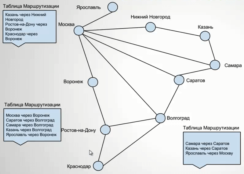
Первое с чем нужно познакомиться, это с понятием таблицы маршрутизации. Если в двух словах это некая карта маршрутов, до сетей о которых знает ваш коммутатор 3 уровня или роутер. Для большей наглядности ее можно сравнить с картой дорог до городов России. И для того, чтобы например мне попасть из Москвы в Нижний Новгород, я должен выбрать определенную дорогу. Так и ваш роутер выбирает ее. Далее если мне нужно из Москвы попасть в Казань, и мне нужно ехать туда через Нижний Новгород, то В НН должен быть свой маршрут до Казани и так далее.
Статический маршрут — это постоянный неизменный маршрут, чаще всего прописанный в ручную.
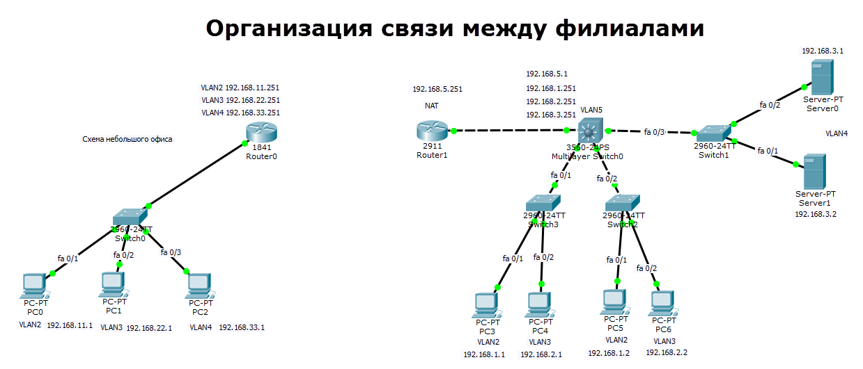
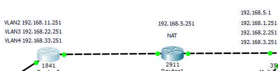
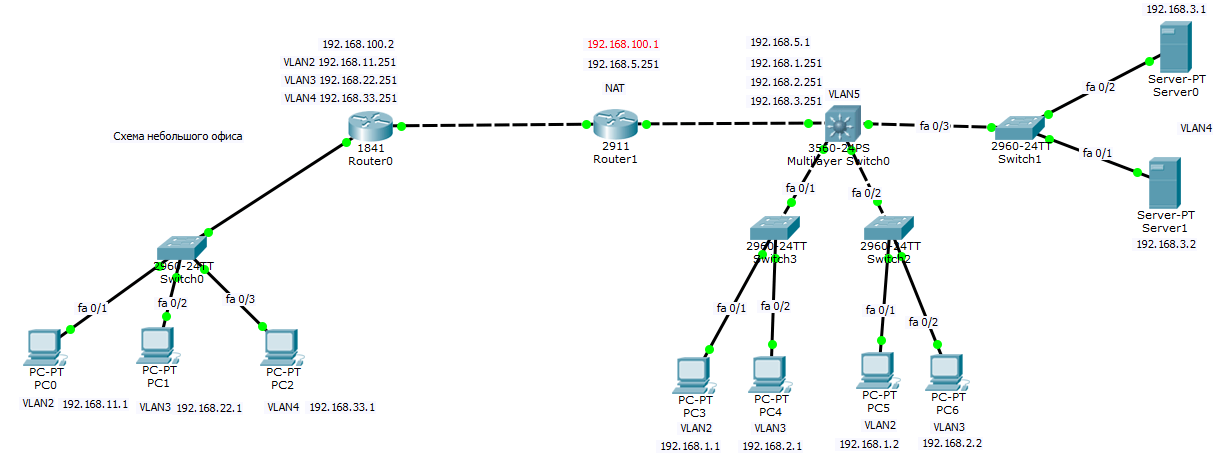
Схема сети офисов
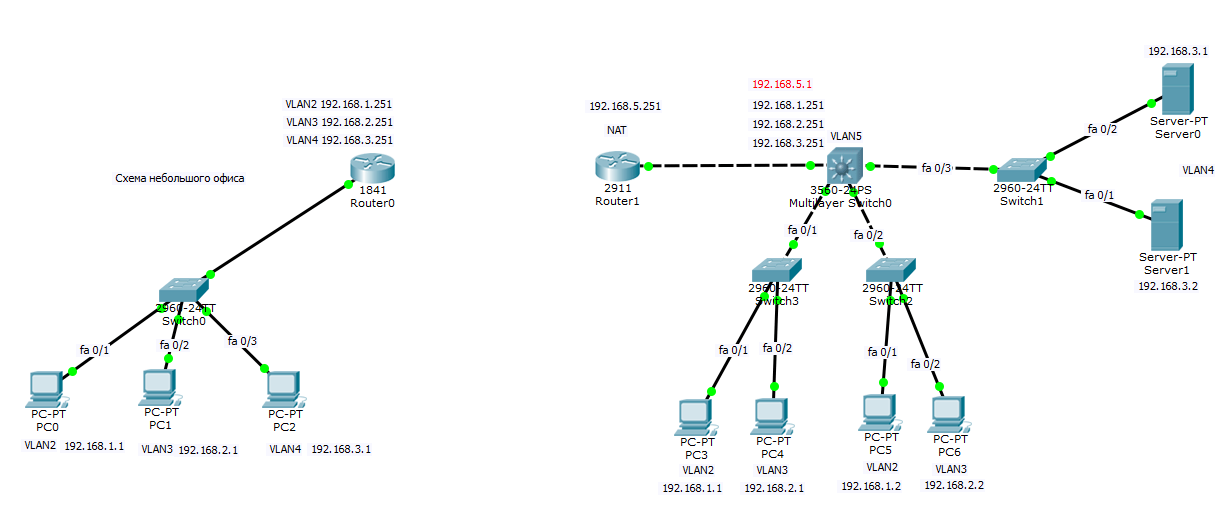
У нас есть филиал, в котором 3 компьютера коммутатор второго уровня Cisco 2960 и Роутер Cisco 1841, есть три vlan (2,3,4). Есть главный офис в котором есть 5 vlan (2,3,4,5), маршрутизацией локального трафика занимается ядро в виде коммутатора 3 уровня Cisco 3560, который VLAN 5 подключен к роутеру Cisco 2911, на котором настроен будет интернет и канал до филиала.
В предыдущем посте где мы создавали данную локальную сеть я не настроил vlan 5 на роутере и ядре, исправим это.
Настройка Cisco 2911 и Cisco 3560
Настройка Cisco 3560
enable
conf t
Создаем Vlan 5
vlan 5
name VLAN5
exit
Настроим ip адрес VLAN5
int vlan 5
ip address 192.168.5.1 255.255.255.0
exit
Добавим порт gi1/1 в VLAN5
int gi0/1
выставляем режим доступа
switchport mode access
switchport access vlan 5
no shutdown
do wr mem
Настройка Cisco 2911
Так как у нас локальной маршрутизацией трафика занимается ядро то тут sub интерфейсов создавать не нужно. Настроим порт роутера gi0/0 на vlan5.
enable
conf t
Настроим ip адрес VLAN5
int gi0/0
ip address 192.168.5.251 255.255.255.0
no shutdown
do wr mem
Добавление статических маршрутов на Cisco 2911
Так как наш роутер Cisco 2911 ничего не знает о сетях 192.168.1.0, 192.168.2.0, 192.168.3.0, то нужно задать ему статические маршруты до них, через ядро делается это следующим образом.
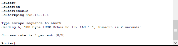
Удостоверимся что пинг не проходит до компьютера 192.168.1.1, вводим на роутере.
Видим ответов нет
Переходим в режим конфигурирования командой
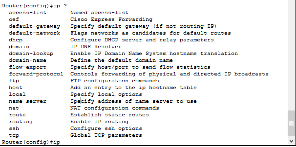
и смотрим команду ip:
Router(config)#ip ?
access-list Named access-list
cef Cisco Express Forwarding
default-gateway Specify default gateway (if not routing IP)
default-network Flags networks as candidates for default routes
dhcp Configure DHCP server and relay parameters
domain IP DNS Resolver
domain-lookup Enable IP Domain Name System hostname translation
domain-name Define the default domain name
flow-export Specify host/port to send flow statistics
forward-protocol Controls forwarding of physical and directed IP broadcasts
ftp FTP configuration commands
host Add an entry to the ip hostname table
local Specify local options
name-server Specify address of name server to use
nat NAT configuration commands
route Establish static routes
routing Enable IP routing
ssh Configure ssh options
tcp Global TCP parameters
Нам нужна команда ip route.
так как ip адрес на ядре сети (Cisco 3560) у VLAN 5 у нас 192.168.5.1 то он будет выступать для нас шлюзом. В итоге пишем.
ip route 192.168.1.0 255.255.255.0 192.168.5.1
ip route 192.168.2.0 255.255.255.0 192.168.5.1
ip route 192.168.3.0 255.255.255.0 192.168.5.1
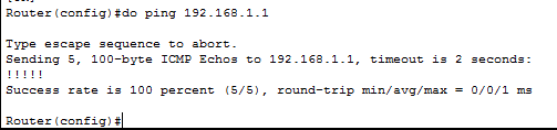
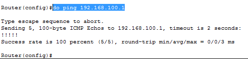
и выполнив теперь команду Ping мы видим. что пакет дошел до 192.168.1.1
Планирование сети
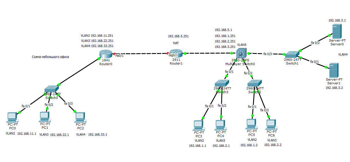
Все бы хорошо, но мы не правильно спланировали сеть в удаленном офисе. Так как там как и в главном, тоже есть сеть 192.168.1.0, 192.168.2.0, 192.168.3.0, такого быть не должно иначе получается дубли. Как правильно планировать сеть я писал тут, вам нужно перенастроить, как ранее описано в предыдущей статье. В итоге в филиале я заменил сети на 11, 22, 33 третьи актеты ip адреса. Общая картина теперь выглядит так.
Соединение роутеров
Соединяем наши роутеры. Предположим, что между ними есть прямой линк, в жизни конечно это VPN канал. настроим в начале роутер Cisco 2911 в главном офисе.
маска тут 32 бита так как нам достаточно всего 2 ip адреса.
enable
conf t
int gi0/1
no shutdown
ip address 192.168.100.1 255.255.255.252
end
wr mem
Теперь настроим роутер Cisco 1841 в филиале. У меня это интерфейс fa0/1
enable
conf t
int fa0/1
ip address 192.168.100.2 255.255.255.252
no shutdown
do wr mem
У нас загорелись порты обоих коммутаторов.
Проверяем пинги с роутеров друг до друга
Видим, что все успешно.
Настройка маршрутов между роутерами
Пробуем например с роутера в филиале пропинговать компьютер 192.168.1.1, и естественно пинг не пройдет так как нет маршрутов, чем мы и займемся. Так как у нас один шлюз соединения между офисами, то правильнее будет прописать один дефолтный путь, но можно и прописывать конкретный статический маршрут, например если основной шлюз интернет и весь трафик по умолчанию идет туда и вы хотите на конкретную сеть завернуть через другой шлюз.
ip route 0.0.0.0 0.0.0.0 192.168.100.1
но если бы нужно было прописать ручками каждый то вот так
ip route 192.168.1.0 255.255.255.0 192.168.100.1
ip route 192.168.2.0 255.255.255.0 192.168.100.1
ip route 192.168.3.0 255.255.255.0 192.168.100.1
do wr mem
Настроим теперь роутер у главного офиса, нам нужно добавить маршруты до сетей 192.168.11.0, 192.168.22.0, 192.168.33.0.
ip route 0.0.0.0 0.0.0.0 192.168.100.2
либо если нужно в ручную отдельным маршрутом.
ip route 192.168.11.0 255.255.255.0 192.168.100.2
ip route 192.168.22.0 255.255.255.0 192.168.100.2
ip route 192.168.33.0 255.255.255.0 192.168.100.2
do wr mem
Настройка маршрутов на ядре
Напомню, что локальный трафик маршрутизирует ядро сети коммутатор 3 уровня Cisco 3560, и на нем нужно тоже указать маршруты, до филиала. В качестве шлюза указывается, ip адрес vlan5 на роутере 2911 192.168.5.251
ip route 192.168.11.0 255.255.255.0 192.168.5.251
ip route 192.168.22.0 255.255.255.0 192.168.5.251
ip route 192.168.33.0 255.255.255.0 192.168.5.251
do wr mem
Вот финальный вид нашей филиальной сети.
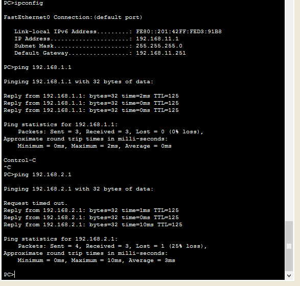
Берем теперь компьютер из филиала с ip адресом 192.16811.1 и пробуем с него пропинговать 192.168.1.1 для примера. И видим, что все отлично пингуется, значит связь между офисами есть.
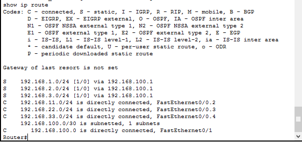
Посмотреть таблицу маршрутизации на Cisco можно командой
Где буква C означает что соединение установлено, буква S означает что маршрут статический.
Вот так вот просто объединить офисы в одну сеть, мы с вами разобрались со статической маршрутизацией, рассмотрели ее на примерах. В организации тестового стенда мне помог симулятор, Скачать Cisco packet tracer можно тут. На этом все.
Материал сайта pyatilistnik.org
Switch#show license feature
Feature name Enforcement Evaluation Clear Allowed Enabled
ipservices yes yes yes no
ipbase yes no yes no
lanbase no no yes yes
Switch#show license fi
Switch#show license file
License Store: Primary License Storage
Store Index: 0
License: 11 lanbase 1.0 LONG NORMAL STANDALONE EXCL INFINITE_KEYS INFINITE
_KEYS NEVER NEVER NiL SLM_CODE CL_ND_LCK NiL *1X6KDW5XHCP25F4400
NiL NiL NiL 5_MINS <UDI><PID>WS-C3560X-24T-L</PID><SN>FDO1747P2KU
</SN></UDI> yJaPWRPQ1VO4nM68DvXf3PgXtM5J,Wk8T,ypXAkAgO3wwqySvIdkR
F0sAUvWAuX4VOoRR,9Y5ax7sSkt16juooLTJBHEcS0sjRTIxvDvv3d0Voozm1qyND
UE8fC4tkVtwcLB$<WLC>AQEBIf8B///7du8IK82WwtcpEEPO798jh93KySr3Egsmr
8SrfejHrR/de6mv2/kPeX0cSRwA+4ZHebPkGlARtYd1UQO7GJ3KnufZ9oZ6JdFniD
f5HrQ8DrXdpCz5RgZE+y8fbN200xiXA5cB3fwcJqoPIFZm2HmD1qFfsyTAzuio66t
6Xk5y8xo1lbVhvoh/FZfy5iRY3oE=</WLC>
Comment:
Hash: 8iRht3eRX9HGEpt7lbpv6YMv66w=
License Store: Evaluation License Storage
Store Index: 0
License: 11 ipservices 1.0 LONG TRIAL DISABLED 1440 DISABLED STANDALONE AD
D INFINITE_KEYS INFINITE_KEYS NEVER NEVER NiL SLM_CODE DEMO NiL N
iL Ni NiL NiL 5_MINS NiL CAORxVRms0Pgk9GAaXYO3UJxU1ygYKTzvmj21bkR
uc3R31Lqkj8kRdeCUAqUaMZcVZ$<WLC>AQEBIQAB//+ieoScBwE/AiB2ai9+tZznU
wNydhE5UCxJOb7Jny9vusIN27slWgVytw5m7vdezm+RqwInXo3s+nsLU7rOtdOxoI
xYZAo3LYmUJ+MFzsqlhKoJVlPyEvQ8H21MNUjVbhoN0gyIWsyiJaM8AQIkVBQFzhr
10GYolVzdzfJfEPQIx6tZ++/Vtc/q3SF/5Ko8XCY=</WLC>
Comment:
Hash: LInf2cvlrUoapigLGVfAyQcdBlo=
Добавлено через 2 минуты
Switch(config)#license boot level ipservices
PLEASE READ THE FOLLOWING TERMS CAREFULLY. INSTALLING THE LICENSE OR
LICENSE KEY PROVIDED FOR ANY CISCO PRODUCT FEATURE OR USING SUCH
PRODUCT FEATURE CONSTITUTES YOUR FULL ACCEPTANCE OF THE FOLLOWING
TERMS. YOU MUST NOT PROCEED FURTHER IF YOU ARE NOT WILLING TO BE BOUND
BY ALL THE TERMS SET FORTH HEREIN.
You hereby acknowledge and agree that the product feature license
is terminable and that the product feature enabled by such license
may be shut down or terminated by Cisco after expiration of the
applicable term of the license (e.g., 30-day trial period). Cisco
reserves the right to terminate or shut down any such product feature
electronically or by any other means available. While alerts or such
messages may be provided, it is your sole responsibility to monitor
your terminable usage of any product feature enabled by the license
and to ensure that your systems and networks are prepared for the shut
down of the product feature. You acknowledge and agree that Cisco will
not have any liability whatsoever for any damages, including, but not
limited to, direct, indirect, special, or consequential damages related
to any product feature being shutdown or terminated. By clicking the
«accept» button or typing «yes» you are indicating you have read and
agree to be bound by all the terms provided herein.
ACCEPT? (yes/[no]):
Introduction
This document describes common issues with Cisco Catalyst 3750 Series Switches and possible ways to resolve them.
Prerequisites
Requirements
There are no specific requirements for this document.
Components Used
The information in this document is based on the Cisco Catalyst 3750 Series Switches.
The information in this document was created from the devices in a specific lab environment. If your network is live, make sure that you understand the potential impact of any command.
Conventions
Refer to Cisco Technical Tips Conventions for more information on document conventions.
Connectivity Issues
Ethernet Speed/Duplex Autonegotiation Mismatches
The IEEE 802.3ab autonegotiation protocol manages the switch settings for speed (10 Mbps, 100 Mbps, and 1000 Mbps that excludes SFP module ports) and duplex (half or full). There are situations when this protocol can incorrectly align these settings and reduce performance.
A mismatch occurs under these circumstances:
-
A manually set speed or duplex parameter of the port is different from the manually set speed or duplex parameter on the connected port.
-
A port is set to autonegotiate, and the connected port is set to full duplex with no autonegotiation.
In order to maximize switch performance and ensure a link, follow one of these guidelines when you change the settings for duplex and speed:
-
Let both ports autonegotiate both speed and duplex.
Or
-
Manually set the speed and duplex parameters for the ports on both ends of the connection.
Note: If a remote device does not autonegotiate, configure the duplex settings on the two ports to match. The speed parameter can adjust itself even if the connected port does not autonegotiate.
SFP Speed/Duplex Autonegotiation Mismatches
You cannot configure speed on SFP module ports, but you can configure speed to not negotiate (nonegotiate) if it is connected to a device that does not support autonegotiation. However, when a 1000BASE-T SFP module is in the SFP module port, you can configure speed as 10, 100, or 1000 Mbps, or auto.
You cannot configure duplex mode on SFP module ports unless a 1000BASE-T SFP module or a 100BASE-FX MMF SFP module is in the port. All other SFP modules operate only in full-duplex mode.
-
When a 1000 BASE-T SFP module is in the SFP module port, you can configure duplex mode to auto or full.
-
When a 100 BASE-FX SFP module is in the SFP module port, you can configure duplex mode to half or full.
Note: Half-duplex mode is supported on Gigabit Ethernet interfaces. However, you cannot configure these interfaces to operate in half-duplex mode.
No Connectivity After IP Routing is Enabled
One of the most common issue people face is the loss of connectivity once IP routing is enabled on the switch. A common cause for this issue is the command used to specify the default gateway for the device.
If IP routing is not enabled on the device, the command is ip default-gateway.
3750-1#ip default-gateway A.B.C.D


!--- where A.B.C.D is the IP address of the default router
If IP routing is enabled, use the ip route command in order to specify the default router for that device.
3750-1#ip route 0.0.0.0 0.0.0.0 A.B.C.D


!--- where A.B.C.D is the IP address of the default router
Intermittent Connectivity Issues due to Ports not Configured as Access Ports when Assigned to a Single VLAN
When ports are assigned to a certain VLANs, the switchport mode access command must be applied to the port in order to put the interface into permanent nontrunking mode and in order to make sure the interface negotiates to convert the link into a nontrunk link. This interface becomes a nontrunk interface even if the neighboring interface does not change.
The port might experience flapping if the switchport mode access command is not applied. The command forces the port to behave as a nontrunk link.
In order to configure an interface as access mode, complete these steps:
-
Access the interface to be configured as an access port:
Switch(config)#interface fastEthernet 0/25
Switch(config-if)#switchport mode access

!--- This command forces the interface go into a permanent nontrunking mode

Switch(config-if)#switchport access vlan 3

!--- This command will assign interface fastethernet 0/25 to vlan 3

Switch(config-if)#no shut
-
When port flapping is seen on a switch check if the command switchport mode access is applied on the flapping interface. Check the output of the command show run.
Switch# show run
Building configuration...

Current configuration : 3183 bytes
!
version 12.1
no service pad
service timestamps debug uptime
service timestamps log datetime
service password-encryption
!

!--- Output supressed.

!
interface FastEthernet0/25
 switchport access vlan 3
 switchport mode access
!
interface FastEthernet0/26
 switchport access vlan 3
!

!--- Output supressed.
Note: Interface FastEthernet0/25 is configured as an access port while interface FastEthernet0/26 is only configured to belong to vlan 3.
Note: Port flapping is seen only when there is a device or host connected to a physical interface.
Catalyst 3750 Switch Receives a High Amount of TCN Packets
When a number of hosts exist in a network, the switches might receive several Topology Change Notification (TCN) packets. For example, when a directly connected server is power cycled, the switch must inform the spanning tree root of the topology change.
When a switch needs to signal a topology change, it starts to send TCN packets on its root port. The designated bridge receives the TCN, acknowledges it, and generates another one for its own root port. The process continues until the TCN hits the root bridge.
An important point to consider is that a TCN does not start an STP recalculation. This fear comes from the fact that TCNs are often associated with unstable STP environments; TCNs are a consequence of this, not a cause. The TCN has an impact only on the aging time. It does not change the topology or create a loop.
When the switch receives a high amount of TCNs on ports, verify that only end devices are connected to those ports. In order to avoid the TCN, you can enable portfast on every port in which there is an end device connected. The switch never generates a TCN when a port configured for portfast goes up or down.
Note: STP Portfast should definitely be avoided on ports that lead to hubs or other bridges.
Refer to Understanding Spanning-Tree Protocol Topology Changes for more information about the topology changes in spanning tree.
If no host or device is connected to the port then the interface VLAN will be in UP/DOWN status
When creating a new VLAN as a Layer 3 interface the status of this VLAN will show up as UP/DOWN when there is no port assigned to it and the status of that port is Not Connected. In order to make the status of this VLAN appear as UP/UP at least one port needs to be assigned to his interface VLAN and a device or host needs to be connected to the port that was assigned to the new interface VLAN.
Example
In this example a new Layer 3 interface VLAN will be created. A port will be assigned to this new VLAN and a device will be connected to this port so the status of the interface VLAN is UP/UP.
-
Create the new VLAN in the database. When exiting the VLAN database mode, the configuration changes are applied.
Switch# vlan database Switch(vlan)# vlan 40 VLAN 40 added: Name: VLAN0040 Switch(vlan)# exit APPLY completed. Exiting.... -
Make sure the VLAN is created in the vlan database. Check the output of the command show vlan.
Switch# show vlan
VLAN Name                             Status    Ports
---- -------------------------------- --------- -------------------------------
1    default                          active    Fa1/0/2, Fa1/0/3, Fa1/0/4
                                                Fa1/0/5, Fa1/0/6, Fa1/0/7
                                                Fa1/0/8, Fa1/0/9, Fa1/0/10
                                                Fa1/0/11, Fa1/0/13, Fa1/0/14
                                                Fa1/0/15, Fa1/0/16, Fa1/0/17
                                                Fa1/0/18, Fa1/0/19, Fa1/0/20
                                                Fa1/0/21, Fa1/0/22, Fa1/0/23
                                                Fa1/0/24, Gi1/0/1, Gi1/0/2
2    VLAN0002                         active
10   data                             active
21   VLAN0021                         active
35   VLAN0035                         active
36   VLAN0036                         active    Fa1/0/12
40   VLAN0040                         active
99   VLAN0099                         active
100  VLAN0100                         active
198  VLAN0198                         active
Note: There is no port assigned to vlan 40.
-
Set an IP address to the newly created VLAN.
Switch(config)# int vlan 40
Switch(config-if)# ip address 10.4.4.1 255.255.255.0
Switch(config-if)# no shut
Switch(config-if)# exit
-
Configure physical interfaces that connect the clients to the corresponding VLAN.
Switch(config)# int fa 1/0/2
Switch(config-if)# switchport mode access
Switch(config-if)# switchport access vlan 40
Switch(config-if)# no shut
-
Check that the physical interface is assigned to the VLAN.
Switch# show vlan VLAN Name Status Ports ---- -------------------------------- --------- ------------------------------- 1 default active Fa1/0/3, Fa1/0/4, Fa1/0/5 Fa1/0/6, Fa1/0/7, Fa1/0/8 Fa1/0/9, Fa1/0/10, Fa1/0/11 Fa1/0/13, Fa1/0/14, Fa1/0/15 Fa1/0/16, Fa1/0/17, Fa1/0/18 Fa1/0/19, Fa1/0/20, Fa1/0/21 Fa1/0/22, Fa1/0/23, Fa1/0/24 Gi1/0/1, Gi1/0/2 2 VLAN0002 active 10 data active 21 VLAN0021 active 35 VLAN0035 active 36 VLAN0036 active Fa1/0/12 40 VLAN0040 active Fa1/0/2 -
At this moment the status of the VLAN will show as UP/DOWN since no host or device is connected to port Fa1/0/2.
Switch# show interface vlan 40
Vlan40 is up, line protocol is down

!--- Output suppressed.
Note: Although there is a port assigned to the VLAN the status of the VLAN still shows as UP/DOWN since there is no device or host physically connected to port Fa1/0/2.
-
Connect a host or device to port Fa1/0/2 which belongs to VLAN 40.
-
Check that the status of port Fa1/0/2 is UP/UP.
Switch# show interface fa1/0/2 FastEthernet1/0/2 is up, line protocol is up !--- Output suppressed. -
Now that there is a port assigned to the new VLAN and the port status is UP/UP the status of the VLAN will show up as UP/UP.
Switch# show interface vlan 40
Vlan40 is up, line protocol is up

!--- Output suppressed.
Note: The status of a Layer 3 VLAN will appear as UP/UP only when there is a port assigned to that VLAN and the status of that port has a status of UP/UP.
Connectivity to IP Phones
DHCP plays an important role for an IP phone to acquire IP address and configure itself. Communication between the IP Phone and DHCP server can be hindered for various reasons. This is a list of the common causes and resolutions:
-
Cisco Discovery Protocol — Refer to Check CDP for IP Phone Connections for more information.
-
IP helper address — Refer to DHCP Service Not Available Across VLANs for more information.
-
Dynamic ARP Inspection — Refer to IP Phones Do Not Get IP Address From DHCP Server for more information.
-
Autonegotiation — Refer to Autonegotiation Valid Configuration Table for more information.
-
Unified Communcations Manager (CallManager) settings — Refer to Solving DHCP and TFTP Problems with Windows 2000 and CallManager IP Phones for more information.
-
DHCP server settings — Refer to IP Phone 7940/7960 Fails to Boot — Protocol Application Invalid for more information.
HTTP Access Issues
Self-Signed Certificate is Lost When the Device Reboots
If the switch is not configured with a host name and a domain name, a temporary self-signed certificate is generated. If the switch reboots, any temporary self-signed certificate is lost, and a new temporary new self-signed certificate is assigned.
If the switch has been configured with a host and domain name, a persistent self-signed certificate is generated. This certificate remains active if you reboot the switch or if you disable the secure HTTP server so that it will be there the next time you enable again a secure HTTP connection.
A temporary or a persistent self-signed certificate is automatically generated when you enable a secure HTTP connection and do not configure the client authentication (CA) trustpoint.
Note: For secure HTTP connections, we highly recommend that you configure a CA trustpoint. If a CA trustpoint is not configured for the device that runs the HTTPS server, the server certifies itself and generates the needed Rivest, Shamir, and Adelman (RSA) key pair. Because a self-certified (self-signed) certificate does not provide adequate security, the client that connects generates a notification that the certificate is self-certified, and the user has the opportunity to accept or reject the connection.
Local User Name not Used for HTTP Access
When you connect to the Catalyst 3750 switch device manager, the switch does not use local user names configured on the device, instead it uses only the secret password or the enable password, only if secret password is not configured.
In order to make the connection secure, you can enable SSL on the device. Refer to Configuring the Switch for Secure Socket Layer HTTP for more information.
Secure HTTP Access is Lost When the Cisco IOS Software is Upgraded
After you upgrade the Cisco IOS® software in Cisco Catalyst 3750 series switches, you can lose the Secure access to the device. If you disable and reenable the access, it does not restore the access. Complete these steps in order to overcome this issue:
-
Disable the Secure HTTP server.
no ip http secure-server
-
Remove the CA Trustpoint or PKI Trustpoint configuration.
no crypto ca trustpoint nameor
no crypto pki trustpoint name -
Use the steps mentioned in the SSL Configuration Guidelines in order to reconfigure the Secure HTTP server .
Power Over Ethernet Issues
Oversubscription of Power
The Power Inline Consumption feature on the Cisco Catalyst 3560 and 3750 Series Power over Ethernet (PoE) products allows the network administrator to configure the actual power requirements of the powered device. This feature allows the administrator to override the powered device classification setting. This feature was requested by many large Enterprise customers and is supported with releases 12.2(25)SEC and later.
These are two scenarios in which the consumption command-line interface (CLI) can be used to manually configure the PoE allocation more efficiently than the automatic algorithms:
-
Currently, the Cisco Catalyst 3750 Series Switch budgets 15.4 W for Class 0 powered devices. However, some of these powered devices require a maximum of less than 15.4 W (for example, the Siemens IP phone requires 5 W). Without the Power Inline Consumption feature, customers could only deploy 24 of these devices. Customers can deploy up to 48 of these devices with the power inline consumption command for configuration of switchport power requirements.
-
Class 3 powered devices are allocated 15.4 W normally. Some IEEE Class 3 powered devices (8-15 W range) use considerably less than 15.4 W maximum. An example is the Avaya 2620SW, which uses 8W in the worst case scenario. If the Consumption CLI configured ports that support this phone to 8 W, a 3750-48PS could safely power 46 phones instead of 24.
Note: Any misconfiguration on the switch (an over-subscription of the power supply) can reduce its reliability or damage the switch. If the power supply is oversubscribed by up to about 20 percent, the switch continues to operate but its reliability can be reduced. Above about 20 percent, the short-circuit protection circuitry triggers and shuts the switch down.
Disabled Port Caused by Power Loss
If a powered device (such as a Cisco IP Phone 7910) that is connected to a PoE switch port and is powered by an AC power source loses power from the AC power source, the device might enter an error-disabled state. To recover from an error-disabled state, enter the shutdown interface configuration command, and then enter the no shutdown interface command.
Disabled Port Caused by False Link Up
If a Cisco powered device is connected to a port and you configure the port with the power inline never interface configuration command, a false link up can occur and palce the port into an error-disabled state. To take the port out of the error-disabled state, change the PoE mode with the power inline, and then enter the shutdown and the no shutdown interface configuration commands. You should not connect a Cisco powered device to a port that has been configured with the power inline never command. In 3750, there is no support for carrier-delay. Also, carrier-delay can be an alternative of link debounce, however it is a feature of the line card hardware and carrier delay is a Layer 3 Cisco IOS mechanism. Thus, Cat3750 does not support either of them.
Phones Cannot Power up After a new Switch is Added to an Existing Stack
This problem occurs when a new switch is added to an existing stack. If workstations are connected to this new switch, the port comes up fine and there is connectivity between the switch and the workstation. When IP phones are connected to the new switch, they are not able to power up, and the port does not come up.
If you experience this issue, make sure the new switch supports PoE in order to power up the IP phones. If the new switch does not support POE, then change the settings in order to allow the switch to support PoE.
Refer to Cisco Catalyst 3750 Q&A for more information on which 3750 models support PoE.
Stack Issues
%STACKMGR-6-SWITCH_ADDED_VM
Software compatibility between the stack members is determined by the Stack Protocol Version number. In order to view the stack protocol version of your switch stack, you can issue the show platform stack-manager all command.
3750-Stk# show platform stack-manager all
                                               Current
Switch#  Role      Mac Address     Priority     State
--------------------------------------------------------
 1       Slave     0016.4748.dc80     5         Ready
*2       Master    0016.9d59.db00     1         Ready


!--- Output suppressed


                 Stack State Machine View
==============================================================

Switch   Master/   Mac Address          Version    Uptime   Current
Number   Slave                          (maj.min)            State
---------------------------------------------------------------------
1        Slave     0016.4748.dc80          1.11        8724    Ready
2        Master    0016.9d59.db00          1.11        8803    Ready


!--- Output suppressed
Switches with the same Cisco IOS software version have the same stack protocol version. Such switches are fully compatible, and all features function properly across the switch stack. Switches with the same Cisco IOS software version as the stack master immediately join the switch stack.
If an incompatibility exists, the fully functional stack members generate a system message that describes the cause of the incompatibility on the specific stack members. The stack master sends the message to all stack members.
Switches with different Cisco IOS software versions likely have different stack protocol versions. Switches with different major version numbers are incompatible and cannot exist in the same switch stack.
3750-Stk# show switch
                                               Current
Switch#  Role      Mac Address     Priority     State
--------------------------------------------------------
 1       Member    0015.c6f5.6000     1         Version Mismatch
*2       Master    0015.63f6.b700     15        Ready
 3       Member    0015.c6c1.3000     5         Ready
Switches with the same major version number, but with a different minor version number as the stack master, are considered partially compatible. When connected to a switch stack, a partially compatible switch enters version-mismatch (VM) mode and cannot join the stack as a fully functional member. The software detects the mismatched software and tries to upgrade (or downgrade) the switch in VM mode with the switch stack image or with a tar file image from the switch stack flash memory. The software uses the automatic upgrade (auto-upgrade) and the automatic advise (auto-advise) features.
The auto-upgrade occurs if the software release that runs on the stack master is compatible with the switch in VM mode and the tar file of the current image is available with any of the stack members. If the tar file of the current image is not available, the auto-advise feature recommends that a compatible image be downloaded with the required commands. The auto-upgrade and auto-advise features do not work if the switch master and switch in VM mode run different feature sets (IP services and IP base) or different cryptographic capabilities (cryptographic and non-cryptographic).
Refer to Switches in the Stack do not Boot the New Image (Version Mismatch) for more information.
%IDBs can not be removed when switch is active
These error messages are received when a switch is removed from the stack:
- %IDBs can not be removed when switch is active
- %Switch can not be un-provisioned when it is physically present
These error messages appear if a switch is removed from a stack and the member value is not changed to the default of 1. In order to resolve this issue, complete these steps:
-
Disconnect the switch that you want to remove from the stack. This includes manually de-stacking the cables in order to remove the switch from the stack.
-
Renumber the switch with this command:
switch current-stack-member-number renumber new-stack-member-number
-
In order to remove a provisioned switch from the switch stack, the configuration associated with the removed stack member remains in the running configuration as provisioned information. In order to completely remove the configuration, use the no switch stack-member-number provision global configuration command.
Refer to Stack Member Numbers for more information on member numbering.
Configuration Issues
DHCP Service Not Available Across VLANs
When the Cisco Catalyst 3750 acts as a DHCP Relay Agent, it might not service clients in VLANs different from the VLAN of the DHCP Server. In order to resolve this issue, complete these steps:
-
Verify if IP routing is enabled on the switch.
-
Verify if VTP version 2 runs in the network.
3750-Stk#show vtp status VTP Version : 2 ! ---- Output suppressed -
Configure the IP helper address of DHCP server on the routed interface.
3750-Stk(config-if)# ip helper-address <IP Address of DHCP Server> -
In the global configuration mode, open the DHCP/BOOTP ports for forwarding requests.
3750-Stk(config)#ip forward-protocol udp bootpc
3750-Stk(config)#ip forward-protocol udp bootps
Unsupported Commands
In Catalyst 3750 Series Switches, some CLI commands are displayed in the CLI help, but are not supported either because they are not tested or because of Catalyst 3750 switch hardware limitations.
Refer to Unsupported Commands in Cisco IOS Release 12.2(25)SEE for the list of commands that are not supported in Cisco IOS Software Release 12.2(35)SE.
Refer to the Catalyst 3750 Switch Software Configuration Guide for other Cisco IOS software releases.
Multicast Does Not Work in the Same VLAN
In Catalyst switches, a common misconfiguration causes multicast traffic to not flow through the switches. Refer to Multicast Does Not Work in the Same VLAN in Catalyst Switches for more information about this issue and the available solutions.
Port Transitions to Err-Disable State Due to Port Security Violations
A port security violation occurs when an address learned or configured on one secure interface is seen on another secure interface in the same VLAN.
SW1-3750#
1d01h: %PM-4-ERR_DISABLE: psecure-violation error detected on Gi2/0/22,
   putting Gi2/0/22 in err-disable state
1d01h: %PORT_SECURITY-2-PSECURE_VIOLATION: Security violation occurred,
   caused by MAC address 0009.434b.c48c on port GigabitEthernet2/0/22.
1d01h: %LINEPROTO-5-UPDOWN: Line protocol on Interface GigabitEthernet2/0/22,
   changed state to down
1d01h: %LINK-3-UPDOWN: Interface GigabitEthernet2/0/22,
   changed state to down SW1-3750#
If you must move from one secure interface to another interface, complete these steps:
-
Use dynamic learning for port security, and remove any static MAC address list or sticky learning configuration.
SW1-3750(config-if)#no switchport port-security mac-address sticky
SW1-3750(config-if)#no switchport port-security mac-address H.H.H


!--- H.H.H is the 48 bit MAC addresses configured
-
Configure port security aging.
The aging time determines the minimum time interval required before the MAC address may appear on a different port.
SW1-3750(config-if)#switchport port-security aging time 1

SW1-3750(config-if)#switchport port-security aging type inactivity
The aging type inactivity ages out the secure addresses on this port only if there is no data traffic from the secure source addresses for the specified time period.
-
Configure err-disable state recovery from port security violation.
SW1-3750(config)#errdisable recovery cause psecure-violation
For more information, refer to the Configuring Port Security section of Configuring Port-Based Traffic Control.
FIB-2-FIBDOWN
FIB-2-FIBDOWN : CEF has been disabled due to a low memory condition.
It can be re-enabled by configuring "ip cef [distributed]"
Before you re-enable the CEF, identify the cause and fix the issue. This error might be caused by one of these issues:
-
The number of not-directly connected routes that the desktop default template allows is exceeded.
If this template is used, the maximum number of 2000 most likely will be exceeded.
As a workaround, issue the sdm prefer routing command, and reload the switch. Ideally, this workaround resolves the problem. For more information, refer to Configuring SDM Templates.
-
The number of MAC addresses learned by the switch has exceeded the amount of space allocated in the hardware to store MAC addresses.
In this case, the show mac-address-table count output shows 0 free entries.
As a workaround, change the Switch Database Management (SDM) template to allow for more space in the unicast MAC address region or prune unnecessary VLANs in order to reduce the number of MAC addresses that are learned by the switch. This issue is documented in the Cisco bug ID CSCef89559 (registered customers only) .
System Clock Resets After Every Reload
A Catalyst 3750 switch or almost all the lower end switches (like 2900 XL, 3500 XL, 2950, 3550, 3560) does not have a battery-supported system clock. Hence, if you manually set the time and date, it will be lost after a reload. Therefore, it is advised to use an external NTP server to manage the system time and date on such switches. For more information on system clock, refer to Managing the System Time and Date section of Administering the Switch .
Note: Cisco recommends that you use manual time and date configuration only if you do not have an outside source to which the switch cannot synchronize.
Switch Loses Static Route Configuration After Reload
After the switch is reloaded or powered down and then powered up, it can lose the static route configuration. In order to check whether the route configuration is present after a reload, check the output of the show run command.
In order to assure the switch does not lose static routes after a reload, complete these steps:
-
Use the ip routing command in global configuration mode in order to enable IP routing on the switch.
3750_Switch(config)#ip routing !--- Enable IP routing for interVLAN routing. -
Add static routes.
-
Issue the write memory command.
3750_Switch#write memory
-
Reload the switch.
-
After the switch is reloaded, issue the show run command in order to verify that the static routes are not lost.
Unable to Log In Through Secure Shell and Telnet
Login attemps fail when you attempt to connect to a 3750 switch through a Secure Shell or Telnet session. Both connections prompt for a password, but do not log you in. You can connect to the switch through the hyperterminal HTTP with that user name and password.
In order to gain access to the switch through SSH or Telnet, use this configuration:
3750_Switch(config)#line vty 0 4
3750_Switch(config-line)#no password <removed>
3750_Switch(config-line)#login local
3750_Switch(config-line)#transport input ssh
3750_Switch(config)#line vty 5 15
3750_Switch(config-line)#no password <removed>
3750_Switch(config-line)#login local
3750_Switch(config-line)#transport input ssh
Log in with this user name and password:
username swadmin password 0 <removed>
Default Route Command Does not Work oin Catalyst 3750 Switch
After you set up the default route for the first time on a 3750 switch with Express Setup, the default gateway does not work.
The ip routing command must be enabled so that the default gateway settings work on a 3750. If it is the first time that the 3750 switch is configured with Express Setup, make sure the ip routing command is enabled since it is not enabled by default.
The command can be enabled using CNA.
-
Apply the ip routing command.
-
Set the default gateway.
Note: The ip route command works only if IP routing is enabled. By default, IP routing is disabled.
Commands Related to Routing Do Not Appear in Running-Config
While you configure route maps in the switch, the commands are accepted by the device, but it is possible that they do not appear in the running-config. This is because the switch currently uses a VLAN SDM template, instead of routing template.
The routing template maximizes system resources for unicast routing, typically required for a router or aggregator in the center of a network, whereas the VLAN template disables routing and supports the maximum number of unicast MAC addresses. It is typically selected for a Layer 2 switch.
Refer to Configuring SDM Templates for more information on SDM templates and its usage.
Upgrade Issues
Stack Does Not Boot with the New Image After a Software Upgrade
Catalyst 3750 Series Switches in the stack might not boot with the new image after a software upgrade. This issue might be caused because you used archive download-sw /leave-old-sw in the download option.
The /leave-old-sw option keeps the old software version after a download. When you enter reload, only the stack master is reloaded. This fails because the switch as a stack expects all models in the stack to have the same version of the image. As a result, the stack master switch is placed in a disable state, and another member switch is elected as master.
In order to recover from this state, use the archive copy-sw command on the stack master to copy the running image from the Flash memory on one stack member to the Flash memory on one or more other stack members. It copies the software image from an existing stack member to the one with incompatible software. That switch automatically reloads and joins the stack as a fully functioning member.
Refer to the Troubleshoot section of Catalyst 3750 Software Upgrade in a Stack Configuration with Use of the Command-Line Interface for other issues related to Cisco IOS software upgrade in Cisco Catalyst 3750 switches.
Unable to create temp dir «flash:update»
This error message can appear when you upgrade the Cisco IOS software:
Unable to create temp dir "flash:update"
This error messages indicates that the temporary directory «update» already exists in the flash: file system, and the current upgrade process is not able to use the directory. The directory could have been left in the flash: file system as a result of any previous upgrade attempts.
In order to resolve this issue, complete these steps:
-
Use the rmdir flash:update command in order to delete the temporary directory.
-
Issue the delete flash:update command.
-
If the rmdir flash:update command does not work, then issue the delete /force /recursive flash:update command.
-
Continue with the Cisco IOS software upgrade procedure.
Performace Issues
High CPU Issues
Before you look at the CPU packet-handling architecture and troubleshoot high CPU utilization, you must understand the different ways in which hardware-based forwarding switches and Cisco IOS software-based routers use the CPU. The common misconception is that high CPU utilization indicates the depletion of resources on a device and the threat of a crash. A capacity issue is one of the symptoms of high CPU utilization on Cisco IOS routers. However, a capacity issue is almost never a symptom of high CPU utilization with hardware-based forwarding switches.
The first step to troubleshoot the high CPU utilization is to check the Cisco IOS version release notes of your Catalyst 3750 switch for the possible known IOS bug. This way you can eliminate the IOS bug from your troubleshooting steps. Refer to Cisco Catalyst 3750 Series Switches Release Notes for the release notes of Cisco IOS software release you are using.
Refer to Catalyst 3750 Series Switches High CPU Utilization Troubleshooting for common high CPU issues and possible resolutions.
High Temperature Issues
The switch may experience an abnormal increase in temperature. This increase can be confirmed by the show environment temperature command.
For example:
Switch#show environment all
FAN is OK
TEMPERATURE is FAULTY
Temperature Value: 127 Degree Celsius
Temperature State: RED
Yellow Threshold : 55 Degree Celsius
Red Threshold    : 65 Degree Celsius
POWER is OK
RPS is NOT PRESENT
If the output shows red as the temperature state or the temperature value goes beyond the threshold value, then the recommended action is to prevent the switch from overheating. As a result, do not operate the switch in an area that exceeds the maximum recommended ambient temperature of 113° F (45° C).
Throughput Issues
The ingress and egress traffic rate on a switchport can vary for various reasons. These can be some of the common causes:
-
The QoS features configured in the switch and especially on the interface. If left as default, the standard QoS settings possibly do not give the optimum performance. If you are not familiar with QoS, then Cisco recommends to use the Auto-QoS feature, available with Cisco Catalyst 3750 switches. If you want to do any manual adjustments to the QoS settings, refer to Configuring Standard QoS and Cisco Catalyst 3750 QoS Configuration Examples for more information.
-
Speed / Duplex setting—If autonegotiaiton is used in the network, negotiation between different vendors possibly do not work as expected. Verify the operation speed / duplex values, and if they are not the desired values, it is recommend to hard code the values at both ends of connection. Refer to Troubleshooting Cisco Catalyst Switches to NIC Compatibility Issues for more information of the autonegotiation.
%SIGNATURE-3-NOT_ABLE_TO_PROCESS: %ERROR:
This error message is seen on 3750/3560 switches during a reboot when configured with the file verify auto command. By default, no file verify auto is not enabled, but the error comes when this is used. As a result, this command has been removed from the later images of these two platforms.
Another error message appears during an attempt to reload.
 %SIGNATURE-3-NOT_ABLE_TO_PROCESS: %ERROR: Not able to process Signature in flash:.
%SIGNATURE-3-ABORT_OPER: %ERROR: Aborting reload
These error messages are specific to 3560 and 3750 switches. This issue is filed as Cisco bug ID CSCsb65707 (registered customers only) . Remove the file verify auto command from the configuration in order to resolve this issue. After the removal of this command, it is possible to reload the router without the error message.
Memory Issues
Memory Exhaustion
When you work with Cisco Catalyst 3750 switches, you may receive the %SYS-2-MALLOCFAIL messages due to a memory leak or fragmentation issue. This message indicates that the process is unable to find a large enough block of contiguous memory. The IP input process attempts to get 1028 bytes from the processor pool of memory, as shown in this example:
%SYS-2-MALLOCFAIL: Memory allocation of 1028 bytes failed from 0x601617A4,
pool Processor, alignment 0 -Process= "IP Input", ipl= 2, pid= 21
The probable causes for these error messages are:
-
Normal Memory Utilization
-
Memory Leaks
-
Memory Fragmentation
Commonly, MALLOCFAIL errors are caused by a security issue, such as a worm or virus that operates in your network. This is especially likely to be the cause if there have not been recent changes to the network, such as a switch IOS upgrade. Usually, a configuration change, such as adding additional lines to your access lists can mitigate the effects of this problem. The Cisco Security Advisories and Notices page contains information on detection of the most likely causes and specific workarounds.
If the %SYS-2-MALLOCFAIL messages are logged, perform these steps:
-
Use the show version command in order to verify that the switch has enough DRAM to support the Cisco IOS software.
3750-Stk#show version
Cisco IOS Software, C3750 Software (C3750-IPBASE-M), Version 12.2(25)SEC2,
  RELEASE SOFTWARE (fc1)
Copyright (c) 1986-2005 by Cisco Systems, Inc.
Compiled Wed 31-Aug-05 08:45 by antonino

ROM: Bootstrap program is C3750 boot loader
BOOTLDR: C3750 Boot Loader (C3750-HBOOT-M) Version 12.2(25r)SEC,
   RELEASE SOFTWARE (fc4)

 SW1-3750 uptime is 6 hours, 32 minutes
System returned to ROM by power-on
System image file is "flash:/c3750-ipbase-mz.122-25.SEC2.bin"

cisco WS-C3750G-24T (PowerPC405) processor (revision L0) with 118784K/12280K
   bytes of memory.

!--- Output suppressed
The switch runs with a DRAM of 128MB (118784K/12280K bytes). Unfortunately, Catalyst 3750 series switches do no support DRAM upgrades. In order to check the minimum memory requirements for Cisco IOS software, cut and paste the show version command output in the Cisco CLI Analyzer (registered customers only) tool. Follow the link provided in the Cisco IOS Image Software Advisor — IOS Image Name section of the analysis output.
-
Some applications have features, such as the User Tracking (UT) Discovery feature of Cisco Works, that can result in low memory conditions unless the ip cef command is issued.
-
Memory allocation failures can be caused by a memory leak bug or memory fragmentation. In this case, analyze the output of the show memory command with the Cisco CLI Analyzer (registered customers only) tool.
-
In order to determine if fragmentation occurred, issue the show memory summary command in order to compare the Largest and Free fields.
Fragmentation occurred if the number in the Largest field is much smaller than the number in the Free field. This is because the Largest field indicates the largest contiguous free memory block and it should normally be close to the free memory, as shown in this example:
SW1-3750#show memory summary
           Head     Total(b)  Used(b)   Free(b)   Lowest(b) Largest(b)
Processor  18AA068  95772568  24384312  71388256  68313048  69338560
      I/O  7400000  12574720  9031656   3543064   3499232   3535816

!--- Output suppressed
This is a brief description of the fields:
-
Total is the total memory allocated to the processor or I/O memory. This value does not include the amount of memory taken up by the Cisco IOS software.
-
Used is the amount of memory used at the time the command is issued.
-
Free is the amount of available free memory at the time the command is issued.
-
Lowest is the lowest amount of memory available since the last reload.
-
Largest is the largest amount of free contiguous memory at the time the command is issued. This should normally be close to the free memory. A small number compared to the free memory indicates fragmentation.
-
-
In order to determine if a memory leak occurred, capture the output of the show memory summary command several times at regular intervals. The intervals depend on the length of time it takes for the memory allocation failures to appear. If the switch begins to display the errors after four days, then one or two captures per day is sufficient to establish a pattern.
If the free memory steadily decreases, a memory leak might have occurred.
A memory leak occurs when a process takes and uses memory, but does not release the memory back to the system. In order to determine the process that caused the problem, issue the show processes memory command and perform these steps:
-
In order to determine which process does not free memory back to the system, capture the show processes memory command output several times at regular intervals.
-
The two counters used for this capture are Freed and Holding. If the Holding counter for a process increases, but the Freed counter does not increase, that process may be the cause of the memory leak.
-
Once the process is identified, refer to the Bug Search Tool (registered customers only) in order to search search for any memory leak issues. This issue relates to the process that affects the Cisco IOS software currently installed on the switch.
-
Cisco Network Assistant Reports that the Switch is Unreachable
When accessing the webpage of the switch or via telnet, Cisco Network Assistant reports that the switch is unreachable.
As a workaround, reboot the switch in order to fix the problem. This type of issue is typically associated with memory leaks. In order to identify the process holding the memory, console in to the switch and analyze the output of the show processes memory sorted command for 3 times in the time interval of every 5 minutes.
Unexpected Memory Consumption in CEF IPC Background Process
When Catalyst 3750 switches are stacked, IP routing is disabled in the switch, and stack master changes, a slow and constant memory leak happens in the Cisco Express Forwarding (CEF) IPC background process. This issue is documented in the Cisco bug ID CSCsc59027 (registered customers only) .
In order to resolve this issue, either enable IP routing or upgrade the switch software to the Cisco IOS release not affected by the bug.
%Error opening flash:/ (Device or resource busy)
After you upgrade to Cisco IOS Software Release 12.2(25)SED, you can experience issues with Flash or NVRAM and receive this error message:
%Error opening flash:/ (Device or resource busy)
The symptoms observed in these scenarios are:
-
An unexpected reload can occur if a switch is renumbered with the switch renumber command.
-
The file system appears to malfunction, and one of these error messages is displayed:
Switch#dir
Directory of flash:/
%Error opening flash:/ (Device or resource busy)
OR
Switch#copy flash:config.text flash:config.also.text
Destination filename [config.also.text]?
i28f128j3_16x_write_bytes: command sequence error
flashfs[1]: writing to flash handle 0x2411CD8, device 0, offset 0x520000,
   length 0x208: Operation Failed
flashfs[1]: sector ptr: {0x29, 0xA3}
%Error opening flash:config.also.text (I/O error)
OR
Switch(config)#boot system flash:
     /c3750-ipservices-mz.122-25.SEC/c3750-ipservices-mz.122-25.SEC.bin
i28f128j3_16x_erase_sector: timeout after 593 polling loops,
     and 0x393AC7D usecs
bs_open[2]: Unable to erase boot_block 0
vb:: I/O error
This issue is documented in the Cisco bug ID CSCsc41813 (registered customers only) . In order to resolve this issue, you can upgrade the switch software to the Cisco IOS release not affected by the bug.
Debug Exception (Could be NULL pointer dereference)
A Catalyst 3750 Series Switch that runs Cisco IOS system software reloads with the Debug Exception (Could be NULL pointer dereference) error message in the logs.
The probable causes for the error message are:
-
Memory leak in CEF background process. For information on how to resolve this issue, see Unexpected memory consumption in CEF IPC Background process.
-
Powered device detection.
This issue occurs when the powered device is detected or classified as an overcurrent class. This issue is documented in Cisco bug ID CSCsa72400 (registered customers only) .
In order to resolve this issue, do not connect IEEE 802.3af non-standard class powered devices (or even bad or loopback cables) to the switch, because the switch can detect the class incorrectly. You can also upgrade the switch software to the Cisco IOS release that is not affected by the bug.
Related Information
- Catalyst 3750 Series Switches High CPU Utilization Troubleshooting
- Catalyst 3750 Software Upgrade in a Stack Configuration with Use of the Command-Line Interface
- Creation and Management of Catalyst 3750 Switch Stacks
- Cisco Catalyst 3750 Series Switches
- Switches Product Support
- LAN Switching Technology Support
- Technical Support & Documentation — Cisco Systems
![]() Download Article
Download Article
![]() Download Article
Download Article
Do you need to enable IP routing on a Cisco switch or router? By default, IP routing is disabled on most Cisco routers and switches. This can prevent devices on different VLANs from communicating with one another. In order for these devices to communicate with one another, the VLAN switches or routers need to have IP routing enabled and configured to route traffic between the two devices. This wikiHow teaches you how to use simple IOS commands to enable IP routing on your Cisco router or switch.
-
1
Connect your computer to the router or switch. If your router has a USB port, you can connect to your PC using a USB connection. If your router only has a Console port, you will most likely need a DB9-to-RJ45 cable. Connect the DB9 end of the cable to the Console port on your router. Then connect the female RJ45 end to a male RJ45 port on your computer. If your computer does not have a male RJ45 port, you can use a female RJ45-to-USB adapter.
- Alternatively, you can use a rollover cable (which is similar to an Ethernet cable, except the pins are reversed on the other end), and connect it to a female DB9-to-RJ45 adapter.
- Warning: Do NOT connect a rollover cable from the Ethernet port on your computer to the Console port on your router or switch. This will blow out the Console port on the router or switch.
-
2
Download a Terminal Emulation program (Windows only). If you are using a Mac or Linux computer, you already have a Terminal program built-in. If you are using a Windows PC, you need to download a terminal emulation program, such PuTTY.
Advertisement
-
3
Find the port number that your Cisco router or switch is connected to. If you are using a DB9-to-RJ45 cable, you will first need to install the drivers that came with the cable. Once you have your Cisco router or switch connected to your PC, use one of the following steps to find out the port number it is connected to:
- Windows: Right-click the Windows Start menu and click Device Manager. Expand «Ports (COM & LPT)» in the list of devices. Note the port number your router is connected to (i.e, «COM1»)
- Mac: Open the Terminal and type cd /dev and press Enter. Then type ls -ltr /dev/*usb* and press Enter. The port number will be listed after «/dev/tty.usbmodem» or » /dev/tty.usbserial».
-
Linux: Open the Terminal and type cd /dev and press Enter. Then type ls -ltr *ACM* and press Enter. The port number will be listed after «/dev/ttyUSB» or «/dev/ttyACM».[1]
-
4
Open a Terminal connection to the router or switch. Once you have the port number it is connected to, use one of the following steps to open a Terminal connection to your router or switch:[2]
-
Windows: Open PuTTY. Select Sessions in the Category menu to the left. Select Serial under «Connection type». Enter the port number the switch is connected to in the box labeled «Serial line.» Leave the speed as «9600». Then click Open.[3]
- Mac: Open the Terminal and type screen /dev/tty.usbmodem[port number] 9600 and press Enter. Replace «[port number]» with the port number you retrieved from the previous step.
- Linux: Open the Terminal and type screen /dev/ttyACM[port number] 9600 and press Enter. Replace «[port number]» with the port number you retrieved from the previous step.
-
Windows: Open PuTTY. Select Sessions in the Category menu to the left. Select Serial under «Connection type». Enter the port number the switch is connected to in the box labeled «Serial line.» Leave the speed as «9600». Then click Open.[3]


Advertisement
-
1
Connect to your router or switch. If you haven’t already done so, connect your router or switch to your computer. Then open a PuTTY or Terminal connection to your router or switch.
-
2
Type enable and press ↵ Enter. This enables EXEC mode. You may be asked to enter a password, if one is set.
-
3
Type configure terminal and press ↵ Enter. This enters Global Configuration mode.
-
4
Type ip routing and press ↵ Enter. This enables IP routing on your router or switch.
- If you want to exit Global Configuration mode, type end and press Enter.


Advertisement
-
1
Understand what Switch Virtual Interfaces are. A single router or switch can host multiple networks called «VLANs» Devices on a VLAN can communicate with each other without the user or a router or switch. However, each VLAN must have a Switch Virtual Interface in order for devices from different VLANs to communicate with each other.[4]
-
2
Enter Global Configuration mode. To enter Global Configuration mode, open a Terminal or PuTTY connection to the switch or router, and type «enable» and press «Enter.» Then type «configure terminal» and press «enter».
-
3
Type interface vlan followed by the VLAN ID and press ↵ Enter. This specifies the VLAN you want to configure. For example, if you wanted to configure VLAN1, you would type interface vlan 1 and press Enter.
-
4
Type ip address followed by the IP address and subnet mask of the network. An example command would be ip address 10.0.0.1 255.255.255.0 This assigns an IP address and subnet mask to the VLAN
-
5
Type end and press ↵ Enter. This exits the VLAN configuration mode and returns you to Global Configuration mode.
- If you want to view statistics for all the VLAN interfaces on your router or switch, type show interfaces vlan [vlan id] and press enter Replace [vlan id] with the actual VLAN ID number.


Advertisement
-
1
Understand what default routes and networks are. When a router receives a packet of information, it checks the destination address to route that information to the proper address. If a packet of information does not have a destination address, you can assign a default address and network to send all packets that do not have a destination address.[5]
-
2
Enter Global Configuraion mode. If you have not already done so, connect to your router or switch using PuTTY or the Terminal. Then type enable and press Enter to enter Exec mode. Then type configure terminal and press Enter to enter Global Configuration mode.
-
3
Type ip route followed by the default IP address and press ↵ Enter. This assigns the default route and network. An example of a default network could be «0.0.0.0 0.0.0.0» To set this as the default network, you would type, ip route 0.0.0.0 0.0.0.0.[6]


Advertisement
Ask a Question
200 characters left
Include your email address to get a message when this question is answered.
Submit
Advertisement
Thanks for submitting a tip for review!
References
About This Article
Thanks to all authors for creating a page that has been read 15,896 times.
Is this article up to date?
![]()
cpatte7372
![]() asked on 1/14/2012
asked on 1/14/2012
Experts,
Fairly simple request. Can someone please explain why I issue the ping command on any of my routers I get the message % Unrecognized host or address, or protocol not running.
I also get the message, ‘Unknown Protocol
Routers

Last Comment
Nayyar HH (CCIE RS)
8/22/2022 — Mon
Try setting route’s interface SPEED manually to 100 Mbps and MODE to Full duplex.
Nayyar HH (CCIE RS)
1/15/2012
either IP and/or ip routing is not enabled on your router
!—to enable ip routing
ip routing
!— enable ip on the router interface
ip address <ip address> <subnet_mask>
no shut
Lastly ensure you the right ip address format is used — IP addresses are made up of four octects
So
ping x.x.x.x
Hi nazsky,
Thanks for responding. I don’t think its a problem with enabling ip routing, as I’m getting the same error message on every router.
I’m thinking the IOS maybe corrupt.
Do you have any other suggestions?
Nayyar HH (CCIE RS)
1/15/2012
OK — Please could post you CLI output
nazsky,
R6#ping
Protocol [ip]:
% Unknown protocol — «», type «ping ?» for help
R6#ping 192.168.1.1
% Unrecognized host or address, or protocol not running.
R6#
THIS SOLUTION ONLY AVAILABLE TO MEMBERS.
View this solution by signing up for a free trial.
Members can start a
7-Day free trial
and enjoy unlimited access to the platform.
Nazsky,
I feel such a pleb. You were correct — I didn’t have ip enabled on any interface.
Thanks
Nayyar HH (CCIE RS)
1/16/2012
Обновлено 16.06.2016
Всем привет сегодня мы с вами поговорим про такую вещь как статическая маршрутизация в оборудовании Cisco. Эта статья продолжение поста Как настроить маршрутизатор cisco / Организация сети для небольшого офиса. Там мы настроили локальную сеть в двух офисах компании, один маленький офис, второй чуть побольше. На роутере во втором офисе мы остановились на настройке статической маршрутизации, чем мы и займемся.
Таблица маршрутизации
Первое с чем нужно познакомиться, это с понятием таблицы маршрутизации. Если в двух словах это некая карта маршрутов, до сетей о которых знает ваш коммутатор 3 уровня или роутер. Для большей наглядности ее можно сравнить с картой дорог до городов России. И для того, чтобы например мне попасть из Москвы в Нижний Новгород, я должен выбрать определенную дорогу. Так и ваш роутер выбирает ее. Далее если мне нужно из Москвы попасть в Казань, и мне нужно ехать туда через Нижний Новгород, то В НН должен быть свой маршрут до Казани и так далее.
Статический маршрут — это постоянный неизменный маршрут, чаще всего прописанный в ручную.
Схема сети офисов
У нас есть филиал, в котором 3 компьютера коммутатор второго уровня Cisco 2960 и Роутер Cisco 1841, есть три vlan (2,3,4). Есть главный офис в котором есть 5 vlan (2,3,4,5), маршрутизацией локального трафика занимается ядро в виде коммутатора 3 уровня Cisco 3560, который VLAN 5 подключен к роутеру Cisco 2911, на котором настроен будет интернет и канал до филиала.
В предыдущем посте где мы создавали данную локальную сеть я не настроил vlan 5 на роутере и ядре, исправим это.
Настройка Cisco 2911 и Cisco 3560
Настройка Cisco 3560
enable
conf t
Создаем Vlan 5
vlan 5
name VLAN5
exit
Настроим ip адрес VLAN5
int vlan 5
ip address 192.168.5.1 255.255.255.0
exit
Добавим порт gi1/1 в VLAN5
int gi0/1
выставляем режим доступа
switchport mode access
switchport access vlan 5
no shutdown
do wr mem
Настройка Cisco 2911
Так как у нас локальной маршрутизацией трафика занимается ядро то тут sub интерфейсов создавать не нужно. Настроим порт роутера gi0/0 на vlan5.
enable
conf t
Настроим ip адрес VLAN5
int gi0/0
ip address 192.168.5.251 255.255.255.0
no shutdown
do wr mem
Добавление статических маршрутов на Cisco 2911
Так как наш роутер Cisco 2911 ничего не знает о сетях 192.168.1.0, 192.168.2.0, 192.168.3.0, то нужно задать ему статические маршруты до них, через ядро делается это следующим образом.
Удостоверимся что пинг не проходит до компьютера 192.168.1.1, вводим на роутере.
Видим ответов нет
Переходим в режим конфигурирования командой
и смотрим команду ip:
Router(config)#ip ?
access-list Named access-list
cef Cisco Express Forwarding
default-gateway Specify default gateway (if not routing IP)
default-network Flags networks as candidates for default routes
dhcp Configure DHCP server and relay parameters
domain IP DNS Resolver
domain-lookup Enable IP Domain Name System hostname translation
domain-name Define the default domain name
flow-export Specify host/port to send flow statistics
forward-protocol Controls forwarding of physical and directed IP broadcasts
ftp FTP configuration commands
host Add an entry to the ip hostname table
local Specify local options
name-server Specify address of name server to use
nat NAT configuration commands
route Establish static routes
routing Enable IP routing
ssh Configure ssh options
tcp Global TCP parameters
Нам нужна команда ip route.
так как ip адрес на ядре сети (Cisco 3560) у VLAN 5 у нас 192.168.5.1 то он будет выступать для нас шлюзом. В итоге пишем.
ip route 192.168.1.0 255.255.255.0 192.168.5.1
ip route 192.168.2.0 255.255.255.0 192.168.5.1
ip route 192.168.3.0 255.255.255.0 192.168.5.1
и выполнив теперь команду Ping мы видим. что пакет дошел до 192.168.1.1
Планирование сети
Все бы хорошо, но мы не правильно спланировали сеть в удаленном офисе. Так как там как и в главном, тоже есть сеть 192.168.1.0, 192.168.2.0, 192.168.3.0, такого быть не должно иначе получается дубли. Как правильно планировать сеть я писал тут, вам нужно перенастроить, как ранее описано в предыдущей статье. В итоге в филиале я заменил сети на 11, 22, 33 третьи актеты ip адреса. Общая картина теперь выглядит так.
Соединение роутеров
Соединяем наши роутеры. Предположим, что между ними есть прямой линк, в жизни конечно это VPN канал. настроим в начале роутер Cisco 2911 в главном офисе.
маска тут 32 бита так как нам достаточно всего 2 ip адреса.
enable
conf t
int gi0/1
no shutdown
ip address 192.168.100.1 255.255.255.252
end
wr mem
Теперь настроим роутер Cisco 1841 в филиале. У меня это интерфейс fa0/1
enable
conf t
int fa0/1
ip address 192.168.100.2 255.255.255.252
no shutdown
do wr mem
У нас загорелись порты обоих коммутаторов.
Проверяем пинги с роутеров друг до друга
Видим, что все успешно.
Настройка маршрутов между роутерами
Пробуем например с роутера в филиале пропинговать компьютер 192.168.1.1, и естественно пинг не пройдет так как нет маршрутов, чем мы и займемся. Так как у нас один шлюз соединения между офисами, то правильнее будет прописать один дефолтный путь, но можно и прописывать конкретный статический маршрут, например если основной шлюз интернет и весь трафик по умолчанию идет туда и вы хотите на конкретную сеть завернуть через другой шлюз.
ip route 0.0.0.0 0.0.0.0 192.168.100.1
но если бы нужно было прописать ручками каждый то вот так
ip route 192.168.1.0 255.255.255.0 192.168.100.1
ip route 192.168.2.0 255.255.255.0 192.168.100.1
ip route 192.168.3.0 255.255.255.0 192.168.100.1
do wr mem
Настроим теперь роутер у главного офиса, нам нужно добавить маршруты до сетей 192.168.11.0, 192.168.22.0, 192.168.33.0.
ip route 0.0.0.0 0.0.0.0 192.168.100.2
либо если нужно в ручную отдельным маршрутом.
ip route 192.168.11.0 255.255.255.0 192.168.100.2
ip route 192.168.22.0 255.255.255.0 192.168.100.2
ip route 192.168.33.0 255.255.255.0 192.168.100.2
do wr mem
Настройка маршрутов на ядре
Напомню, что локальный трафик маршрутизирует ядро сети коммутатор 3 уровня Cisco 3560, и на нем нужно тоже указать маршруты, до филиала. В качестве шлюза указывается, ip адрес vlan5 на роутере 2911 192.168.5.251
ip route 192.168.11.0 255.255.255.0 192.168.5.251
ip route 192.168.22.0 255.255.255.0 192.168.5.251
ip route 192.168.33.0 255.255.255.0 192.168.5.251
do wr mem
Вот финальный вид нашей филиальной сети.
Берем теперь компьютер из филиала с ip адресом 192.16811.1 и пробуем с него пропинговать 192.168.1.1 для примера. И видим, что все отлично пингуется, значит связь между офисами есть.
Посмотреть таблицу маршрутизации на Cisco можно командой
Где буква C означает что соединение установлено, буква S означает что маршрут статический.
Вот так вот просто объединить офисы в одну сеть, мы с вами разобрались со статической маршрутизацией, рассмотрели ее на примерах. В организации тестового стенда мне помог симулятор, Скачать Cisco packet tracer можно тут. На этом все.
Материал сайта pyatilistnik.org
-

-
January 25 2016, 19:09
- IT
- Компьютеры
- Cancel
Добрый День!
Столкнулся сегодня с проблемой:
— Cisco IE3010 с несколькими IP интерфейсами на разных VLAN
— ip routing выключен (устройство работает как свитч)
— один из IP интерфейсов используется для связи с NTP сервером, от которого синхрится сама Cisco
— другие IP интерфейсы используются для раздачи синхры внутри сегментов
— есть статические маршруты для удалённых IP-сегментов, находящихся за другими маршрутизаторами
Маршрутизация между сегментами на самой Cisco выключена специально, этого надо избежать.
Но статика не работает, пока не включишь «ip routing». Без включения маршрутизации работает только default gateway — но этого не хватает, так как удалённых сегментов — несколько.
Можно, конечно, включить маршрутизацию и на все интерфейсы навесить access-list и route-map. Но это какие-то лишние сущности в данной ситуации. Я был 100% уверен, что маршрутизация в даном случае должна работать аналогично маршрутизации на обычных рабочих станциях, где несколько интерфейсов отлично уживаются с несколькими статическими маршрутами.
Что скажете? Есть какой-то простой способ решить данную проблему?