
Introduction
If the ERROR lamp lights, check the message displayed on the front panel. Following type of error
messages are displayed:
- Service errors: Operator unrecoverable errors, such as hardware or software failure. Contact HP Support.
-
Communication protocol errors:
Take appropriate measures according to the error code or message. -
Operator errors:
The operator can correct these errors. Take appropriate measures according to the message.
note:
If a communication error or a data error occurs, the ERROR lamp does not light. An
error message appears on the front panel and disappears when the next operation is
performed.
Service errors
If any of the following service error messages appears, turn the power switch Off and
then On again. This may release the error:
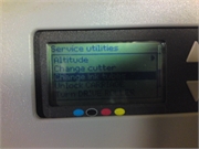
POC error messages
Figure : INITIALIZING menu

Issue: An unrecoverable error has occurred in the engine section. This error message appears when an error is detected during self-diagnosis when the power is turned On.
Solution: Make a note of the error code shown on the front panel. Contact HP Support.
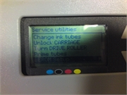
Engine error messages
Figure : ENGINE ERROR menu

Issue: An unrecoverable error has occurred in the network controller section (hardware failure).
Solution: Make a note of the error code displayed on the front panel. Contact HP Support.
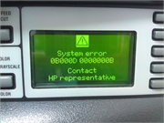
System error messages
Figure : F_es menu

Issue: An unrecoverable error has occurred (firmware failure).
Solution: Make a note of the error code displayed on the front panel. Contact HP Support.
Operator error messages
The following errors can be corrected by the operator:
Ink cartridge error message
Figure : OPEN INKCOVER menu

X: L (left), R (right)
YY: Y, M, C, K, Lm, Lc
- Y: Yellow
- M: Magenta
- C: Cyan
- K: Black
- Lm: Light magenta
- Lc: Light cyan
Issue: There is no ink.
Figure : OPEN INKCOVER menu

X: L (left), R (right)
YY: Y, M, C, K, Lm, Lc
- Y: Yellow
- M: Magenta
- C: Cyan
- K: Black
- Lm: Light magenta
- Lc: Light cyan
Z: Error code (1 to 9)
Issue: An ink cartridge error has occurred.
Figure : OPEN INKCOVER menu

X: L (left), R (right)
YY: Y, M, C, K, Lm, Lc
- Y: Yellow
- M: Magenta
- C: Cyan
- K: Black
- Lm: Light magenta
- Lc: Light cyan
Issue: No ink cartridge is installed.
Figure : INKCOVER OPEN menu

X: L (left), R (right)
Issue: Ink cover is open.
Solution: Follow the instructions on the front panel.
Figure : INK NEAR menu

X: L (left), R (right)
YY: Y, M, C, K, Lm, Lc
Issue: The ink cartridge is nearing its expiration date.
Figure : INK PAST menu

X: L (left), R (right)
YY: Y, M, C, K, Lm, Lc
Issue: The ink cartridge has passed its expiration date.
The ink LED flashes
Issue: Ink is running out (warning).
Solution: Prepare a new ink cartridge.
Waste ink bottle is not installed
Figure : BOTTLE OUT menu

Issue: The waste ink bottle is not installed.
Solution: Insert a new waste ink bottle into the printer and install the waste ink bottle cover.
Waste ink bottle is full
Figure : BOTTLE FULL menu

Issue: The waste ink bottle is full.
Solution: Follow the instructions on the front panel.
Media crash
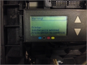
Figure : WARNING menu

Issue: Media crash (1) indicates that the carriage is blocked by obstacles in the carriage path or media feed path.
Solution: Follow the instructions on the front panel. If the media jam (1) occurs frequently and there are no media jams or obstructions in the carriage path or media feed path, contact HP Support.
Figure : WARNING menu

Issue: Media jam (2) indicates that the media is not detected correctly. The wrong media format may have been selected while loading the media or a cut sheet with an irregular size may have been used.
Solution: Follow the instructions on the front panel and check the media settings.
Media
Figure : NO MEDIA LOADED menu

Issue: There is no media loaded in the printer.
Solution: Load media.
Figure : MEDIA SIZE ERROR menu

Issue: An invalid media size is set (less than 297 mm wide or 64 inch wide or more).
Solution: Set the correct size.
Figure : NO MEDIA LOADED menu

Issue: There is media skew.
Solution: Reload the media. Skew may be caused by ink deposits on the platen. Check the platen for ink deposits and clean any ink.
Figure : LOAD MEDIA menu

Issue: The media lever has not been lowered.
Solution: Lower the media lever.
Error LED is flashing
Issue: The take-up reel is not winding the media correctly.
Solution: Check that the media is correctly detected by the take-up reel sensor. Check that the media is loaded correctly.
Other error messages
Figure : CLOSE REAR COVER menu

Issue: The rear cover is open.
Solution: Close the rear cover.
Figure : PH TEMP ERROR menu

Issue: The temperature of the printheads exceed the operating temperature range.
Solution: Allow the printheads to cool by not using the printer until the printhead temperature returns to the operating temperature range.
Figure : ENV. TEMP ERROR menu

Issue: The ambient temperature is not within the operating temperature range for the printer.
Solution: Use the printer within its operating temperature range (15o degree Celsius to 30o degree Celsius).
Introduction
If the ERROR lamp lights, check the message displayed on the front panel. Following type of error
messages are displayed:
- Service errors: Operator unrecoverable errors, such as hardware or software failure. Contact HP Support.
-
Communication protocol errors:
Take appropriate measures according to the error code or message. -
Operator errors:
The operator can correct these errors. Take appropriate measures according to the message.
note:
If a communication error or a data error occurs, the ERROR lamp does not light. An
error message appears on the front panel and disappears when the next operation is
performed.
Service errors
If any of the following service error messages appears, turn the power switch Off and
then On again. This may release the error:
POC error messages
Figure : INITIALIZING menu
Issue: An unrecoverable error has occurred in the engine section. This error message appears when an error is detected during self-diagnosis when the power is turned On.
Solution: Make a note of the error code shown on the front panel. Contact HP Support.
Engine error messages
Figure : ENGINE ERROR menu
Issue: An unrecoverable error has occurred in the network controller section (hardware failure).
Solution: Make a note of the error code displayed on the front panel. Contact HP Support.
System error messages
Figure : F_es menu
Issue: An unrecoverable error has occurred (firmware failure).
Solution: Make a note of the error code displayed on the front panel. Contact HP Support.
Operator error messages
The following errors can be corrected by the operator:
Ink cartridge error message
Figure : OPEN INKCOVER menu
X: L (left), R (right)
YY: Y, M, C, K, Lm, Lc
- Y: Yellow
- M: Magenta
- C: Cyan
- K: Black
- Lm: Light magenta
- Lc: Light cyan
Issue: There is no ink.
Figure : OPEN INKCOVER menu
X: L (left), R (right)
YY: Y, M, C, K, Lm, Lc
- Y: Yellow
- M: Magenta
- C: Cyan
- K: Black
- Lm: Light magenta
- Lc: Light cyan
Z: Error code (1 to 9)
Issue: An ink cartridge error has occurred.
Figure : OPEN INKCOVER menu
X: L (left), R (right)
YY: Y, M, C, K, Lm, Lc
- Y: Yellow
- M: Magenta
- C: Cyan
- K: Black
- Lm: Light magenta
- Lc: Light cyan
Issue: No ink cartridge is installed.
Figure : INKCOVER OPEN menu
X: L (left), R (right)
Issue: Ink cover is open.
Solution: Follow the instructions on the front panel.
Figure : INK NEAR menu
X: L (left), R (right)
YY: Y, M, C, K, Lm, Lc
Issue: The ink cartridge is nearing its expiration date.
Figure : INK PAST menu
X: L (left), R (right)
YY: Y, M, C, K, Lm, Lc
Issue: The ink cartridge has passed its expiration date.
The ink LED flashes
Issue: Ink is running out (warning).
Solution: Prepare a new ink cartridge.
Waste ink bottle is not installed
Figure : BOTTLE OUT menu
Issue: The waste ink bottle is not installed.
Solution: Insert a new waste ink bottle into the printer and install the waste ink bottle cover.
Waste ink bottle is full
Figure : BOTTLE FULL menu
Issue: The waste ink bottle is full.
Solution: Follow the instructions on the front panel.
Media crash
Figure : WARNING menu
Issue: Media crash (1) indicates that the carriage is blocked by obstacles in the carriage path or media feed path.
Solution: Follow the instructions on the front panel. If the media jam (1) occurs frequently and there are no media jams or obstructions in the carriage path or media feed path, contact HP Support.
Figure : WARNING menu
Issue: Media jam (2) indicates that the media is not detected correctly. The wrong media format may have been selected while loading the media or a cut sheet with an irregular size may have been used.
Solution: Follow the instructions on the front panel and check the media settings.
Media
Figure : NO MEDIA LOADED menu
Issue: There is no media loaded in the printer.
Solution: Load media.
Figure : MEDIA SIZE ERROR menu
Issue: An invalid media size is set (less than 297 mm wide or 64 inch wide or more).
Solution: Set the correct size.
Figure : NO MEDIA LOADED menu
Issue: There is media skew.
Solution: Reload the media. Skew may be caused by ink deposits on the platen. Check the platen for ink deposits and clean any ink.
Figure : LOAD MEDIA menu
Issue: The media lever has not been lowered.
Solution: Lower the media lever.
Error LED is flashing
Issue: The take-up reel is not winding the media correctly.
Solution: Check that the media is correctly detected by the take-up reel sensor. Check that the media is loaded correctly.
Other error messages
Figure : CLOSE REAR COVER menu
Issue: The rear cover is open.
Solution: Close the rear cover.
Figure : PH TEMP ERROR menu
Issue: The temperature of the printheads exceed the operating temperature range.
Solution: Allow the printheads to cool by not using the printer until the printhead temperature returns to the operating temperature range.
Figure : ENV. TEMP ERROR menu
Issue: The ambient temperature is not within the operating temperature range for the printer.
Solution: Use the printer within its operating temperature range (15o degree Celsius to 30o degree Celsius).
 Одной из первых моделей в линейке designjet у которых табло стало выдавать системные ошибки является 500 модель (hp designjet500). Ниже приводится таблица ошибок от данной модели.
До сегодняшнего дня после 500 модели вышло огромное количество других моделей, изменился и дизайн и оформление и скорость печати самих плоттеров. Неизменными остались только ошибки плоттеров, не считая мелких поправок и изменений. Но в общих чертах все без изменений.
Каждая ошибка содержит комбинацию из четырех цифр АА:ББ
Внимание! Уважаемые посетители нашего сайта, рады Вам предложить акцию от компании Дока-Сервис!
Кликайте на фото

Ниже приводятся 3 таблицы, по которым можно определить характер ошибки и причину ее возникновения.
таблица АА
| АА | Деталь плоттера Component/System | |
| ENGLISH | РУССКИЙ | |
| 01 | Main PCA/Electronics Module | Главный модуль PCA / плата электроники |
| 02 | Carriage/Carriage PCA | Каретка PCA |
| 03 | Power Supply Unit | Блок питания |
| 04 | Network Card | Сетевая карта |
| 05 | Formatter | Форматер |
| 06 | Hard Disk Drive | Жесткий диск |
| 07 | Interconnect PCA | Плата управления PCA |
| 08 | Front Panel | Панель управления |
| 11 | Trailing Cable | Шлейф каретки |
| 12 | Carriage Flex Circuit | Контакты печатающих головок |
| 17 | Interconnect Cable | Кабель платы управления |
| 21 | Service Station | Станция обслуживания, бункер отработки |
| 22 | Ink Supply Station | Станция подкачки чернил |
| 23 | Pressure System (APS) | Система давления APS |
| 24 | Ink Delivery System | Система поставки чернил |
| 25 | Spittoon | Губка-впитыватель чернил |
| 31 | Cutter | Нож, резак |
| 32 | Take-up Reel | Натяжитель |
| 33 | Sheet Feeder | Устройство подачи бумаги |
| 34 | Dryer/Blower | Вентилятор сушки |
| 41 | Paper-Axis Motor | Двигатель оси протяжки бумаги |
| 42 | Scan-Axis Motor | Двигатель привода ремня каретки |
| 43 | Vacuum Fan | Вакуумный вентилятор |
| 44 | Aerosol fan | Вентилятор аэрозоля |
| 51 | Window Sensor | Датчик открытия главной крышки |
| 52 | Drop Detector | Датчик вспрыска |
| 53 | Media Sensor | Датчик наличия бумаги |
| 54 | Pinch-Arm Sensor | Датчик ручки прижима рулона |
| 55 | Line Sensor | Датчик линейки позиционирования |
| 56 | Drive Roller Encoder Sensor | Датчик квадратуры оси протяжки рулона |
| 57 | Ink Leak Detector | Датчик расхода чернил |
| 58 | Color Sensor | Датчик цвета |
| 59 | Media Type Sensor | Датчик вида носителя |
| 61 | Language Interpreting | Языковая интерпретация |
| 62 | Input/Output through Parallel Port | Ввод-вывод параллельного порта |
| 63 | Input/Output through Network Card | Ввод-вывод сетевой карты |
| 64 | Input/Output through USB Port | Ввод-вывод USB порта |
| 65 | Input/Output | Ввод-вывод |
| 71 | Memory Management | Управление памяти |
| 72 | Generic Firmware | Общие микропрограммы |
| 73 | Servo | Контроль |
| 79 | Assertion | Внутрений контроль |
| 81 | Media Advance | Механизм носителя |
| 82 | Media Cut | Отрез носителя |
| 83 | Single-Sheet Feeding | Подача одиночного листа |
| 84 | Roll Feeding | Подача рулона |
| 85 | Media-Axis Encoder Reading | Датчик оборотов двигателя оси |
| 86 | Carriage Movement | Передвижение каретки |
| 87 | Scan-Axis Encoder Reading | Датчик оборотов двигателя привода ремня |
| 91 | Printhead Firing | Вспрыск печатающей головы |
| 92 | Servicing | Обслуживание |
| 93 | Ink Pumping | Помпа давления чернил |
таблица ББ
Possible for customer to perform action
Действие может быть выполнено пользователем
| ББ | Действие Recovery Action | |
| ENGLISH | РУССКИЙ | |
| 00 | Replace | Заменить |
| 01 | Reseat/(manually)Reconnect/Clean/Adjust | Переустановить / Переподключить / Очистить / Отрегулировать |
| 02 | Calibrate/Adjust (using Automatic Process) | Откалибровать / Отрегулировать |
| 03 | Power OFF | Отключить питание |
| 04 | Upgrade System Firmware | Обновить прошивку |
| 05 | Upgrade Driver | Обновить драйвер |
| 06 | Add Accessory | Добавить дополнительные модули |
| 07 | Escalate | Расширить память |
| 08 | Send Plot Again | Отправить печать заново |
| 09 | Wrong Part Installed | Установлен неправильный модуль |
талица ББ
On-Site visit required
Требуется вмешательство специалиста
| ББ | Действие Recovery Action | |
| ENGLISH | РУССКИЙ | |
| 10 | Replace | Заменить |
| 11 | Reseat/(manually)Reconnect/Clean/Adjust | Переустановить / Переподключить / Очистить / Отрегулировать |
| 12 | Calibrate/Adjust (using Automatic Process) | Откалибровать / Отрегулировать |
| 13 | Power OFF | Отключить питание |
| 14 | Upgrade System Firmware | Обновить прошивку |
| 15 | Upgrade Driver | Обновить драйвер |
| 16 | Add Accessory | Добавить дополнительные модули |
| 17 | Escalate | Расширить память |
| 18 | Send Plot Again | Отправить печать заново |
| 19 | Wrong Part Installed | Установлен неправильный модуль |
Руководствуясь данной таблицей можно самостоятельно решить большинство проблем с ошибками плоттеров. Не компетентное вмешательство может привести к серьезной проблеме. Компания не несет ответственность если пользователь руководствуясь таблицей ошибок сам разобрал плоттер пытаясь его реанимировать, а в результате сделал еще хуже. Ремонт дорогой и профессиональной техники лучше предоставить опытному сервисному инженеру.
Примеры самых распространенных ошибок плоттеров HP designjet
| Код ошибки | Действия |
|
01:10 01.1:10 |
Самая серьезная ошибка, которая говорит, что вышел из строя главный модуль плоттера или проще материнская плата. Ремонту не подлежит, блок электроники меняется целиком. |
| 02:10 02.1:10 |
Причина, вышла из строя плата каретки. Ремонту не подлежит, замена каретки в сборе. |
| 03:10 | Проблема с блоком питания. иногда возможен ремонт, либо установка нового блока питания. |
| 05:10 |
Часто возникает среди моделей HP Designjet 500, 510 и 800, в которых установлена плата расширения, либо плата форматтера, в зависимости от модели. Выходит из строя либо сама плата или жесткий диск, который используется в некоторых моделях. Лечится заменой вышедшего из строя элемента. |
| 08:11 |
Обычно возникают в моделях Т и Z сериях. Передняя панель при старте не может найти связь с платой форматтера. Решение-смотреть ошибку 05:10 |
| 11:11 | В процессе непрерывной работы изнашивается подвижный кабель передачи информации между электронным модулем и блоком каретки. Лечится заменой шлейфа, меняются обе жилы. |
| 21:10 или 21:13 | Связана с выходом из строя сервисной станции (бункер отработки). Возникновение ошибки можно избежать своевременной профилактикой вашего плоттера раз в 1,5-2г. Применимо в моделях 100-х серий, 500, 510 и 800 моделях. В Т и Z сериях только под замену. |
| 22:10 или 22:13 |
Часто возникает при использовании СНПЧ, происходит утечка чернил, заливается плата управления узла подачи чернил (Ink Sistem) и узел выходит из строя, также риск возникновения увеличивается при использовании не оригинальных или заправляемых картриджей, чипы которых также сжигают электронику данного узла. И очень редко от времени и физического износа. Устраняется ошибка заменой узла целиком. |
| 41:10 или 41:13 |
Возникает при сбоях работы двигателя протяжки рулона. Требуется заменить двигатель. |
| 47:01 |
Возникает только в моделях Т и Z сериях. Выходит из строя двигатель, отвечающий за движение планки прижима рулона. На двигателе имеются три передаточные шестерни сидящие на хрупких осях, которые со временем просто обламываются от нагрузки. Устраняется заменой двигателя прижима рулона. |
| 61:05 |
Обычно возникает у старых моделях из за нехватки памяти при обработке задания. Часто пропадает после установки дополнительной карты памяти. |
| 79:04 |
Так же ошибка обработки задания, только причина ошибки связана или с прошивкой, или с просроченными расходниками (печатающие головы либо картриджи). Устраняется соответственно либо обновлением микропрограммы, либо заменой просроченного расходника. |
| 81:01 | Неверное позиционирование по оси Y. Выходит из строя плата квадратуры считывающая информацию о перемещении рулона вперед-назад. Замена платы квадратуры (датчик энкодера). |
| 86:01 |
Самая интересная ошибка, которая в документации характеризуется как ошибка замятия бумаги, которой в большинстве случаях и в помине нет. Работал плоттер и встал. А возникает всегда при отклонении движения каретки по оси следования. То есть проще говоря, все что мешает движению каретки приводит к сбою и возникновению данной ошибки. К примеру каретка подмяла лист и каретка встала-ошибка. Сервисная станция не ушла до конца в посадочное место, каретка при движении опять ударятся в парковку, действие не закончено-ошибка. Износ ремня привода каретки ,шаги перемещения ремня не соответствуют реальному передвижению-ошибка, износ ленты позиционирования, опять каретка не считывает свое местоположение-ошибка, либо перелом шлейфа каретки, который подминается под каретку при движении-опять ошибка. В данном случае квалифицированный подход, выявление причины, устранение дефекта и установка новой детали. |
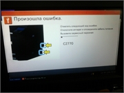
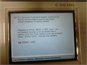
| Ошибка принтера или системы печати Данная ошибка выскакивает только в плоттерах серии DesignJet T120 и T520. У данной ошибки нет нумерации, так как ошибка может быть связана с несколькими узлами. Это сама печатающая головка, потом картриджи, плата каретки и шлейф каретки. Более подробно и детально данная ошибка описана в нашей статье. |
|
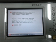
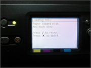
| Ошибка загрузки носителя HP DesignJet T520 | T525 | T530| T120 | T125 | T130 |
По каждой модели есть отдельные статьи с видео-материалами, детально описаны ошибки и полезный контент. Если Вам нужна помощь пишите в чат, поможем с навигацией намного быстрее.
Если Вы не нашли нужную информацию выше, то из таблицы выберите Вашу модель плоттера и попадёте на список системных ошибок связанные с плоттером и методы их решения.
| — hp designjet 100 | — hp designjet T125 | — hp designjet T1120 | — hp designjet Z2100 |
| — hp designjet 110 | — hp designjet T130 | — hp designjet T1200 | — hp designjet Z2600 |
| — hp designjet 111 | — hp designjet T520 | — hp designjet T1300 | — hp designjet Z3100 |
| — hp designjet 130 | — hp designjet T525 | — hp designjet T1500 | — hp designjet Z3200 |
| — hp designjet 430 | — hp designjet T530 | — hp designjet T1530 | — hp designjet Z5200 |
| — hp designjet 500 | — hp designjet T610 | — hp designjet T1600 | — hp designjet Z5400 |
| — hp designjet 510 | — hp designjet T620 | — hp designjet T1700 | — hp designjet Z5600 |
| — hp designjet 800 | — hp designJet T730 | — hp designjet T1708 | — hp designjet Z6100 |
| — hp designjet 1050 | — hp designjet T770 | — hp designjet T2300 | — hp designjet Z6200 |
| — hp designjet 1055 | — hp designjet T790 | — hp designjet T2500 | — hp designjet Z6600 |
| — hp designjet 4000 | — hp designjet T795 | — hp designjet T2530 | — hp designjet Z6800 |
| — hp designjet 4500 | —hp designJet T830 | — hp designjet T2600MFP | — hp designjet Z6 |
| — hp designjet 5000 | — hp designjet T920 | — hp designjet T3500 | — hp designjet Z9+ |
| — hp designjet 5500 | — hp designjet T930 | — hp designjet T7100 | — hp designjet D5800 |
| — hp designjet T120 | — hp designjet T1100 | — hp designjet T7200 | — hp designjet L26500 |
 Для увеличения кликайте на фото
 |
 |
 |
 |
 |
 |
 |
 |
 |
 |
 |
 |
 |
 |
 |
 |
 |
 |
 |
Если вы столкнулись с такими проблемами, свяжитесь с нами по телефонам : 8 ( 499 ) 720 — 60 — 20
Консультация специалиста : 8 ( 925 ) 090 — 60 — 50
Либо заполните форму заявки о неисправности вашего аппарата
Будем рады Вам помочь!
Для навигации по сайту Вы можете писать в онлайн чат, наши консультанты с удовольствием Вам помогут.
Вернуться в главное меню 
System Error Codes System Error: System Error 119x: Head Relay Variable Supply Error Problem Description: 2-10 Output voltages of the Head Relay Board are abnormal. Corrective Action: Try the following: Check whether 36V is supplied to the Main PCA. If not, then: – Make sure that the Rear Cover is closed. – Replace Power Supply Unit ⇒ Page 8-43. Preset the Head Relay Board Voltage from the Diagnostic Menu. Use a circuit tester to check the voltages of the channels that have an error. If the voltage is supplied, it means that the voltage check circuit is defective. Replace the Main PCA ⇒ Page 8-35. If the voltage is not supplied, replace the Head Relay Board ⇒ Page 8-40. There is a possibility of a short circuit off the Head Relay Board output line. Perform a short circuit test on the Main PCA. Make sure the Carriage Trailing Cable is connected correctly and is not damaged. System Error: System Error 11Ax: NVRAM Error Problem Description: The data in the NVRAM is incorrect. Corrective Action: Try the following: Switch the Printer OFF and ON again and check if the error still appears. If the error continues, skip the Power-ON Self-Diagnostic by keeping the Cancel Key pressed and powering ON the Printer. Perform NVRAM Initialization (⇒ Page 4-47) and then perform Restore Calibs (⇒ Page 4-48). Switch the Printer OFF and ON again and check if the error still appears. If the error continues, restore the Printer to defaults settings. Switch the Printer OFF and ON again and check if the error still appears. Check whether the NVRAM is mounted on the Main PCA correctly. If necessary, replace the NVRAM ⇒ Page 8-39. If the error continues, replace the Main PCA ⇒ Page 8-35. System Error: System Error 11C0: Cap Position Error Problem Description: The Carriage position sensors have detected more than a 2mm gap during the capping operation. Corrective Action: Try the following: Make sure that the Encoder Strip is not stained. Make sure that the Encoder Sensor is mounted correctly and that the cable is connected correctly. Make sure that the Trailing Cable is connected correctly. Replace the Carriage PCA ⇒ Page 8-91. If the error continues, replace the Main PCA ⇒ Page 8-35. <strong>HP</strong> <strong>Designjet</strong> 9000s Series Printer <strong>Service</strong> <strong>Manual</strong>
System Error: System Error 11D0: Cooling Fan Error Problem Description: <strong>HP</strong> <strong>Designjet</strong> 9000s Series Printer <strong>Service</strong> <strong>Manual</strong> System Error Codes When the Printhead temperature reaches above 43oC, the Printer will check whether the temperature drops below 43 o C during printing. This error will appear if the temperature does not drop below 43 o C after 10 minutes. Corrective Action: Try the following: Make sure that the Printhead Cooling Fans are working correctly. If the Printhead Cooling Fans are not working correctly, replace them ⇒ Page 8-82. Make sure that the Printer Cooling Fans are connected and working correctly. System Error: System Error 11E0: Long Term Storage Error Problem Description: This error is displayed when the Printer has been left switched OFF for more than 31 days. Corrective Action: Try the following: This error can be avoided if the «Store Ink System» procedure is performed before turning the Printer OFF for long periods. To clear this error: – Turn the Printer ON in error skip mode by holding down the Cancel and Shift keys and pressing the ON button. – Enter the Password to clear the internal error flag: , , Shift and OK. – Switch the Printer OFF and then ON again. System Error: System Error 120x: Printhead Drive IC Error Problem Description: The Piezo Drive IC on a Printhead is too hot (85 o C or higher) or too low (- 10 o C or lower). Corrective Action: Try the following: Check whether the temperature of the Printhead voltage circuit on the Carriage PCA is extremely hot. If it is extremely high, check the short-circuit of the Printhead and the Printhead Cable using a tester. The Short-circuit may have been caused by the incorrect insertion of the Printhead Cable, internal failure of the Printhead or by a foreign object attached to the Carriage PCA. Replace the Printhead ⇒ Page 8-35. Replace the Carriage PCA ⇒ Page 8-91. 2-11
- Page 2: For HP Internal Use Only ©Copyrigh
- Page 5 and 6: HP Designjet 9000s Series Printers
- Page 7 and 8: HP Designjet 9000s Series Printers
- Page 9 and 10: Troubleshooting 1 HP Designjet 9000
- Page 11 and 12: HP Designjet 9000s Series Printer S
- Page 13 and 14: Solving Heater Problems HP Designje
- Page 15 and 16: HP Designjet 9000s Series Printer S
- Page 17 and 18: System Error Codes 21 Introduction
- Page 19 and 20: Self-Diagnostic Errors at Power On
- Page 21 and 22: Boot-Up Error: FPGA (Main PCA) (002
- Page 23 and 24: System Error Codes HP Designjet 900
- Page 25: System Error: System Error 1170: Te
- Page 29 and 30: Replace the Main PCA ⇒ Page 8-35.
- Page 31 and 32: Heater Error Codes HP Designjet 900
- Page 33 and 34: Heater Error: Heater Error H08: Cen
- Page 35 and 36: Printhead Adjustment 3 Introduction
- Page 37 and 38: Calibrate the Printhead Adjustment
- Page 39 and 40: Printhead HP Designjet 9000s Series
- Page 41 and 42: Printhead Adjustment 7 The followin
- Page 43 and 44: Press the Left Arrow Key to select
- Page 45 and 46: Perform Printhead Position Correcti
- Page 47 and 48: HP Designjet 9000s Series Printer S
- Page 49 and 50: Adjust the Printhead HP Designjet 9
- Page 51 and 52: Printhead Adjustment 8 If the devia
- Page 53 and 54: Tip to Speed-Up the Printhead Adjus
- Page 55 and 56: This corner of the Printhead should
- Page 57 and 58: Maintenance Mode 4 Introduction 4-2
- Page 59 and 60: Maintenance Mode Menus HP Designjet
- Page 61 and 62: 8 ELECT (Electronics) ⇒ Page 4-59
- Page 63 and 64: Entering the Maintenance Mode Enter
- Page 65 and 66: Menu Selection HP Designjet 9000s S
- Page 67 and 68: HP Designjet 9000s Series Printer S
- Page 69 and 70: HP Designjet 9000s Series Printer S
- Page 71 and 72: HP Designjet 9000s Series Printer S
- Page 73 and 74: Press the Left Arrow Key to select
- Page 75 and 76: HP Designjet 9000s Series Printer S
- Page 77 and 78:
HP Designjet 9000s Series Printer S
- Page 79 and 80:
Press the Down Arrow Key to select
- Page 81 and 82:
HP Designjet 9000s Series Printer S
- Page 83 and 84:
HP Designjet 9000s Series Printer S
- Page 85 and 86:
HP Designjet 9000s Series Printer S
- Page 87 and 88:
HP Designjet 9000s Series Printer S
- Page 89 and 90:
HP Designjet 9000s Series Printer S
- Page 91 and 92:
HP Designjet 9000s Series Printer S
- Page 93 and 94:
HP Designjet 9000s Series Printer S
- Page 95 and 96:
HP Designjet 9000s Series Printer S
- Page 97 and 98:
HP Designjet 9000s Series Printer S
- Page 99 and 100:
HP Designjet 9000s Series Printer S
- Page 101 and 102:
Press the Left Arrow Key to select
- Page 103 and 104:
HP Designjet 9000s Series Printer S
- Page 105 and 106:
HP Designjet 9000s Series Printer S
- Page 107 and 108:
HP Designjet 9000s Series Printer S
- Page 109 and 110:
Press the Up Arrow Key to select SE
- Page 111 and 112:
The Sensors that can be tested in t
- Page 113 and 114:
HP Designjet 9000s Series Printer S
- Page 115 and 116:
Press the Left Arrow Key to select
- Page 117 and 118:
HP Designjet 9000s Series Printer S
- Page 119 and 120:
HP Designjet 9000s Series Printer S
- Page 121 and 122:
HP Designjet 9000s Series Printer S
- Page 123 and 124:
HP Designjet 9000s Series Printer S
- Page 125 and 126:
Press the Down Arrow Key to select
- Page 127 and 128:
HP Designjet 9000s Series Printer S
- Page 129 and 130:
HP Designjet 9000s Series Printer S
- Page 131 and 132:
HP Designjet 9000s Series Printer S
- Page 133 and 134:
Press the Up Arrow Key to select SY
- Page 135 and 136:
Press the Left Arrow Key to select
- Page 137 and 138:
HP Designjet 9000s Series Printer S
- Page 139 and 140:
HP Designjet 9000s Series Printer S
- Page 141 and 142:
HP Designjet 9000s Series Printer S
- Page 143 and 144:
Heater Panel Maintenance Mode HP De
- Page 145 and 146:
Adjustments and Calibrations 5 Adju
- Page 147 and 148:
Belt Tension Adjustment This adjust
- Page 149 and 150:
Carriage Height Adjustment This adj
- Page 151 and 152:
Adjustments and Calibrations 7 Loos
- Page 153 and 154:
Scan-Axis Belt Tension Adjustment T
- Page 155 and 156:
Paper-Axis Belt Tension Adjustment
- Page 157 and 158:
Wiping Station Height Adjustment Th
- Page 159 and 160:
Adjustments and Calibrations 8 Gent
- Page 161 and 162:
Wiper Blade Height Adjustment This
- Page 163 and 164:
Adjustments and Calibrations 8 Manu
- Page 165 and 166:
HP Designjet 9000s Series Printer S
- Page 167 and 168:
Wiping Position Calibration This ca
- Page 169 and 170:
Capping Position Calibration This c
- Page 171 and 172:
Line Sensor Calibration (Side Margi
- Page 173 and 174:
Print Quality 6 Print Quality 6-2 P
- Page 175 and 176:
Using the IQ Print to Troubleshoot
- Page 177 and 178:
Troubleshooting Print Quality Probl
- Page 179 and 180:
Image is Completely Blank or Faded
- Page 181 and 182:
Parts and Diagrams 7 Right Hand Cov
- Page 183 and 184:
2 1 4 5 9 Figure 1: Right Hand Cove
- Page 185 and 186:
1 2 4 6 Figure 2: Left Hand Covers
- Page 187 and 188:
2 1 Figure 3: Center Covers HP Desi
- Page 189 and 190:
2 5 1 Figure 4: Electronics Module
- Page 191 and 192:
1 2 Figure 5: Control Panels HP Des
- Page 193 and 194:
5 4 6 2 Figure 6: Carriage Assembly
- Page 195 and 196:
1 2 Figure 7: Scan-Axis Assemblies
- Page 197 and 198:
2 7 6 3 8 4 Figure 8: Paper Path As
- Page 199 and 200:
5 2 Figure 9: Media Entry Assemblie
- Page 201 and 202:
2 HP Designjet 9000s Series Printer
- Page 203 and 204:
3 2 5 Figure 11: Capping Assemblies
- Page 205 and 206:
2 3 5 Figure 12: Wiping Assemblies
- Page 207 and 208:
1 4 5 Figure 13: Ink Supply and Sub
- Page 209 and 210:
4 HP Designjet 9000s Series Printer
- Page 211 and 212:
1 2 Figure 15: Service Tools HP Des
- Page 213 and 214:
Removal and Installation 8 Introduc
- Page 215 and 216:
Rear Cover Removal Switch off the p
- Page 217 and 218:
Top Side Cover (Left or Right) Remo
- Page 219 and 220:
HP Designjet 9000s Series Printer S
- Page 221 and 222:
Left Subtank Cover Removal Switch o
- Page 223 and 224:
Right Subtank Cover Removal Switch
- Page 225 and 226:
Lower Capping Cover Removal Switch
- Page 227 and 228:
Capping Door Removal Switch off the
- Page 229 and 230:
HP Designjet 9000s Series Printer S
- Page 231 and 232:
Ink Cartridge Door (Left or Right)
- Page 233 and 234:
Electronics Module Cover Removal Sw
- Page 235 and 236:
HP Designjet 9000s Series Printer S
- Page 237 and 238:
Front Panel Removal Switch off the
- Page 239 and 240:
Heater Panel Removal Switch off the
- Page 241 and 242:
Front Heater Removal Switch off the
- Page 243 and 244:
Rear Heater Removal Switch off the
- Page 245 and 246:
Center Platen Removal Switch off th
- Page 247 and 248:
Main PCA Removal Switch off the pro
- Page 249 and 250:
HP Designjet 9000s Series Printer S
- Page 251 and 252:
NVRAM Removal Switch off the produc
- Page 253 and 254:
HP Designjet 9000s Series Printer S
- Page 255 and 256:
Power Supply Unit Removal Switch of
- Page 257 and 258:
HP Designjet 9000s Series Printer S
- Page 259 and 260:
HP Designjet 9000s Series Printer S
- Page 261 and 262:
Waste Bottle Sensor Removal Switch
- Page 263 and 264:
HP Designjet 9000s Series Printer S
- Page 265 and 266:
HP Designjet 9000s Series Printer S
- Page 267 and 268:
HP Designjet 9000s Series Printer S
- Page 269 and 270:
Media Lever Sensor Removal Switch o
- Page 271 and 272:
Rear Cover Sensor Removal Switch of
- Page 273 and 274:
HP Designjet 9000s Series Printer S
- Page 275 and 276:
HP Designjet 9000s Series Printer S
- Page 277 and 278:
HP Designjet 9000s Series Printer S
- Page 279 and 280:
HP Designjet 9000s Series Printer S
- Page 281 and 282:
HP Designjet 9000s Series Printer S
- Page 283 and 284:
HP Designjet 9000s Series Printer S
- Page 285 and 286:
Carriage Drive Assembly (Includes C
- Page 287 and 288:
HP Designjet 9000s Series Printer S
- Page 289 and 290:
Trailing Cable Removal Switch off t
- Page 291 and 292:
Cut Cable Ties HP Designjet 9000s S
- Page 293 and 294:
HP Designjet 9000s Series Printer S
- Page 295 and 296:
HP Designjet 9000s Series Printer S
- Page 297 and 298:
HP Designjet 9000s Series Printer S
- Page 299 and 300:
HP Designjet 9000s Series Printer S
- Page 301 and 302:
Printhead Connector Assembly Remova
- Page 303 and 304:
Carriage PCA Removal Switch off the
- Page 305 and 306:
HP Designjet 9000s Series Printer S
- Page 307 and 308:
Encoder Sensor Removal Switch off t
- Page 309 and 310:
Line Sensor Removal Switch off the
- Page 311 and 312:
Ink Pump Assembly Removal HP Design
- Page 313 and 314:
Ink Supply Station (Left or Right)
- Page 315 and 316:
HP Designjet 9000s Series Printer S
- Page 317 and 318:
HP Designjet 9000s Series Printer S
- Page 319 and 320:
HP Designjet 9000s Series Printer S
- Page 321 and 322:
HP Designjet 9000s Series Printer S
- Page 323 and 324:
Capping Station Assembly Removal Sw
- Page 325 and 326:
HP Designjet 9000s Series Printer S
- Page 327 and 328:
HP Designjet 9000s Series Printer S
- Page 329 and 330:
HP Designjet 9000s Series Printer S
- Page 331 and 332:
HP Designjet 9000s Series Printer S
- Page 333 and 334:
Prime Assembly Removal Switch off t
- Page 335 and 336:
HP Designjet 9000s Series Printer S
- Page 337 and 338:
Solenoid Assembly Removal Switch of
- Page 339 and 340:
HP Designjet 9000s Series Printer S
- Page 341 and 342:
Wiping Station Assembly Removal Swi
- Page 343 and 344:
HP Designjet 9000s Series Printer S
- Page 345 and 346:
Wiper Cleaning Assembly Removal Swi
- Page 347 and 348:
HP Designjet 9000s Series Printer S
- Page 349 and 350:
HP Designjet 9000s Series Printer S
- Page 351 and 352:
HP Designjet 9000s Series Printer S
- Page 353 and 354:
HP Designjet 9000s Series Printer S
- Page 355 and 356:
HP Designjet 9000s Series Printer S
- Page 357 and 358:
Preventive Maintenance 9 Printheads
- Page 359 and 360:
Daily Inspection and Maintenance HP
- Page 361 and 362:
HP Designjet 9000s Series Printer S
- Page 363 and 364:
Capping Door Capping Unit HP Design
- Page 365 and 366:
HP Designjet 9000s Series Printer S
- Page 367 and 368:
HP Designjet 9000s Series Printer S
- Page 369 and 370:
HP Designjet 9000s Series Printer S
- Page 371 and 372:
About this Edition This is the 1st
![]()

For HP Internal Use Only Warranty
©Copyright Hewlett-Packard Company 2006
This document contains proprietary information that is protected by copyright. All rights are reserved. No part of this document may be photocopied, reproduced, or translated to another language without the prior written consent of Hewlett-Packard Company.
First Edition, March 2006
The information contained in this document is subject to change without notice.
Hewlett-Packard makes no warranty of any kind with regard to this material, including, but not limited to, the implied warranties of merchantability and fitness for a particular purpose.
Hewlett-Packard shall not be liable for errors contained herein or for incidental or consequential damages in connection with the furnishing, performance, or use of this material.
Content Management Department, Barcelona Division, Hewlett-Packard Espanola, S.A. Avda. Graells, 501
08190 Sant Cugat del Valles Spain
WARNING
The procedures described in this manual are to be performed by HP-qualified service personnel only.
Electrical Shock Hazard
Serious shock hazard leading to death or injury may result if you do not take the following precautions:
—Ensure that the ac power outlet (mains) has a protective earth (ground) terminal.
—Disconnect the Printer from the power source prior to performing any maintenance.
—Prevent water or any other liquids from running onto electrical components or circuits, or through openings in the enclosure.
Electrostatic Discharge
Refer to the beginning of Chapter 4of this manual, for precautions you should take to prevent damage to the Printer circuits from electrostatic discharge.
Safety Symbols
General definitions of safety symbols are given immediately after the table of contents.
WARNING
The Warning symbol calls attention to a procedure, practice, or the like, which, if not correctly performed or adhered to, could result in personal injury. Do not proceed beyond a Warning symbol until the indicated conditions are fully understood and met.
CAUTION
The Caution symbol calls attention to an operating procedure, practice, or the like, which, if not correctly performed or adhered to, could result in damage to or destruction of part or all of the product. Do not proceed beyond a Caution symbol until the indicated conditions are fully understood and met.
Using this Manual
Purpose
This Service Manual contains information necessary to test, calibrate and service:
HP Designjet 9000s Series Printers (Model Q6665A).
For information about using these printers, refer to the corresponding User and Quick Reference Guides.
Readership
The procedures described in this Service Manual are to be performed by HP Certified service personnel only.
Part Numbers
Part Numbers for Printer options, accessories and service parts are located in Chapter 7.
Conventions
A small arrow is used to indicate other parts of the Service Manual where you can find information related to the topic you are consulting.
Safety Precautions
The following Warnings and Cautions are presented in this Service Manual and must be observed.
Follow the instructions marked with these symbols.
Failure to follow the guidelines marked with this symbol could result in severe personal injury or death.
Failure to follow the guidelines marked with this symbol could result in minor personal injury or product and/or peripheral damage.
|
2 |
HP Designjet 9000s Series Printers Service Manual |
Inks used in the printer and liquids in the HP Cleaning and Maintenance kits contain an organic solvent (ethylene glycol monobutyl ether acetate, CAS No. 112-07-2). Observe all local, state, and federal regulations related to the handling, use, storage, and disposal of organic solvents.
Avoid contact between ink and skin, eyes, and clothing.
Immediately wash skin with soapy water.
Remove clothing soaked with ink from contact with skin.
Use an approved eye wash station if ink is splashed into eyes and consult a doctor if necessary.
If an approved eye wash station is unavailable, flush eyes with cold water and consult a doctor if necessary.
Be sure the printer is well-grounded. Failure to ground the printer may result in electrical shock, fire, and susceptibility to electromagnetic interference.
Ink and fluids used in the Cleaning and Maintenance Kits are combustible. Do not use or store within 8 meters (25 feet) of open flames, sparks, or other sources of ignition.
Switch power OFF, remove the power cords from the electric outlets and allow the printer to cool before attempting to remove any panels or covers. The printer contains high voltage and hot components. Removal of panels or covers may result in exposure to electric shock and burns.
Do not allow metal or liquids (except those used in HP Cleaning and Maintenance Kits) to touch the internal parts of the printer. Doing so may cause fire, electric shock, or other serious hazards.
When shutting down the entire system, always turn OFF the printer switch as well as the heater switch (breaker).
Use only an HP Waste Ink Bottle. The bottle must be installed according to instructions or waste ink may overflow.
An HP Waste Ink Bottle must always be installed before turning the printer ON. Automatic and manual service cycles produce waste ink that must be contained in an HP Waste Ink Bottle.
Always use both hands to remove and carry an HP Waste Ink
Bottle.
Keep the HP Waste Ink Bottle upright. Do not place on tables or shelves where it could fall.
|
HP Designjet 9000s Series Printers Service Manual |
3 |

Waste ink is combustible. Keep an HP Waste Ink Bottle containing waste ink away from open flames, sparks, or other sources of ignition.
Never store waste ink in a glass container.
Never pour waste ink into a container filled with other chemicals.
The HP Waste Ink Bottle contains organic solvents and must be disposed of in compliance with all local, state, and federal regulations.
Always securely replace the cap on a full or partially-full the HP Waste Ink Bottle after removing it from the printer to prevent ink spills.
|
4 |
HP Designjet 9000s Series Printers Service Manual |
Treat any media, paper, used cleaning and maintenance supplies, and wipes soaked with ink as combustible materials. Handle and dispose of properly.
Do not clean the printer with benzene or paint thinner. This may damage the paint.
Wipe the printer clean with a soft cloth. A cloth moistened with a neutral detergent may be used. Do not allow liquid to enter the printer. This may create risk of fire and electrical shock and cause a malfunction.
Never touch the printhead nozzles. They can be easily damaged or clogged.
Do not touch heater surfaces in the paper path. This may cause burns. Take care when touching printer components near the heaters.
HP Ink Cartridges must be installed before the “Install By” printed on the cartridge. Use of the Ink Cartridge 3 months beyond the “Install By” date may cause deterioration in print quality or a printer malfunction.
Do not separate the cap from a new HP Waste Ink Bottle. The cap is needed to properly seal the HP Waste Ink Bottle for disposal.
The level in the HP Waste Ink Bottle should be checked by visual inspection to prevent overflow. If the waste ink level is above the indication line, the bottle must be replaced with an empty HP Waste Ink Bottle.
The use of safety glasses and gloves is recommended when performing cleaning and maintenance operations.
|
HP Designjet 9000s Series Printers Service Manual |
5 |

Table of Contents |
|
|
Table of Contents |
1 |
Troubleshooting 1-1
System Error Codes 2-1
Head Adjustment 3-1
Maintenance Mode 4-1
Adjustments and Calibrations 5-1
Print Quality 6-1
Parts and Diagrams 7-1
Removal and Installation 8-1
Preventive Maintenance 9-1
|
6 |
HP Designjet 9000s Series Printers Service Manual |

Troubleshooting 1 1
Introduction 1-2
Troubleshooting System Error Codes 1-2 Performing a Service Test on a Failed Assembly 1-2
Performing the Necessary Service Calibrations or Adjustments 1-3 Solving Print Quality Problems 1-3
The Printer does not Power ON 1-3 Cover Sensors are not Working 1-3
The File Sent is Not Processed Immediately 1-3 Paper Jams Occur Frequently 1-4
Print Speed is Very Slow 1-4
No Ink Message when there is Enough Ink 1-4 Abnormal Sound Coming from the Printer 1-4 Front Panel is Not Working 1-4
Heater Panel is Not Working 1-4 Solving Heater Problems 1-5
«Power ON Heater Power Switch» appears on Heater Panel 1-5 Heater Does NOT become Hot 1-5
Abnormal Temperature is Displayed 1-5
The Heater Temperature Becomes Extremely High 1-5 «Initializing» Continuously Appears on the Heater Panel 1-5 «Power Save Mode» Continuously Appears on the Heater Panel 1-6
Special Power On Procedure 1-6
Both NVRAM and Main PCA are Replaced Together 1-7
|
HP Designjet 9000s Series Printer Service Manual |
1-1 |

Troubleshooting
Guide to Troubleshooting the Printer
Introduction
This chapter will guide you through the relevant steps to take when troubleshooting the Printer.
Troubleshooting System Error Codes
Chapter 2 — System Error Codes contains a list of system error codes and their respective descriptions and recommended corrective actions. Only try one recommended action at a time and check if the error code has disappeared.
If you have an error code which is not documented in this Service Manual or you have an error which you cannot resolve, then report the error to the HP Response Center or the nearest HP Support Office. When reporting the error, have the following information ready:
Model and Serial Number of the printer.
Which firmware revision the printer is using.
The complete error number.
The System and History Prints.
Which software application the customer is using (name, version, etc.).
Whenever an Error Message is displayed, you should try to switch the Printer Off and then On again to see if the error disappears. If the error disappears, there is no need to troubleshoot the Printer any further.
Performing a Service Test on a Failed Assembly
If possible, always perform a Service Test on the component/assembly that you are about to replace, just to make sure that is the actual component/ assembly that has failed.
If the test on that component/assembly passes, you should
NOT replace it.
For information on the Service Tests and how to use them see Chapter 4 —
Maintenance Mode.
|
1-2 |
HP Designjet 9000s Series Printer Service Manual |
![]()
Troubleshooting
Performing the Necessary Service Calibrations or
Adjustments
Is the printer calibrated or adjusted correctly after replacing a component? For information on the Service Calibrations and Adjustments and how to use them, see Chapter 5 — Adjustments and Calibrations.
Remember that certain Calibrations or Adjustments are required even if an Assembly has been disassembled to gain access to another Assembly or Component.
Solving Print Quality Problems
Whenever a Print Quality problem appears, it is advisable to print the Test Print to help diagnose the problem. The Test Print will help you differentiate between possible Printhead errors or mechanical problems. For information on solving Print Quality problems see Chapter 6 — Print Quality.
The Printer does not Power ON
1Check that the power cord is connected correctly to the Printer and to the Power Socket.
2Check that the Power Switch on the BACK of the Printer is in the ON position.
3Replace the Power Supply Unit Page 8-43.
Cover Sensors are not Working
1Perform the Sensors Test Page 4-53.
2Check if the cable for the faulty sensor is not damaged and is connected correctly.
3Replace the faulty Sensor.
The File Sent is Not Processed Immediately
1Check that the USB Cable is connected correctly to the Computer and the Printer and that it is NOT damaged.
2Check that the Data LED on the Front Panel is flashing. If it is flashing and nothing is printed, then maybe the file sent is corrupted or too big.
3Make sure that the Printer is in the Online state when the file is sent. The file will be rejected if the file is sent when the Printer is in the Offline state.
|
HP Designjet 9000s Series Printer Service Manual |
1-3 |

Troubleshooting
Paper Jams Occur Frequently
1Make sure that the paper type setting matches the type of paper loaded into the Printer.
2Open the Rear Cover and check for any visible obstacles in the paper path. If there is a wrinkled mass of paper inside the paper path, lift the Pinchwheels (using the Media Lever) and clear the obstruction.
3Make sure that the Vacuum Fans are working correctly.
Print Speed is Very Slow
1 Make sure that the Printer is being used at temperatures of 20oC or higher.
No Ink Message when there is Enough Ink
1Make sure that the Ink Cartridge is installed correctly.
2Check that the connector in the Ink Cartridge is NOT damaged.
3Make sure that the Ink Cartridge Sensors are working correctly. Perform the Ink Sensor Test Page 4-54.
Abnormal Sound Coming from the Printer
1One of the Motors in the Printer might be defective. Check that the Motors are working correctly Page 4-70.
2Check that there are no foreign or loose objects inside the Printer.
Front Panel is Not Working
1Make sure that the Front Panel Cable is connected correctly to the Front Panel and to the Main PCA.
2Make sure that the Front Panel Cable is NOT damaged.
3Replace the Front Panel Page 8-25.
Heater Panel is Not Working
1Make sure that ALL Heater Panel Cables are connected correctly to the Heater Panel.
2Make sure that the Heater Panel Cables are NOT damaged.
3Replace the Heater Panel Page 8-27.
|
1-4 |
HP Designjet 9000s Series Printer Service Manual |

Troubleshooting
Solving Heater Problems
«Power ON Heater Power Switch» appears on Heater Panel
1Check that the Heater Power Cable is connected and that the heater Power Switch is switched On.
2Replace the Heater Relay Assembly Page 8-46.
3Replace the Heater Panel Page 8-27.
Heater Does NOT become Hot
1Try performing the Heater Test Page 4-88. If the Heater does not work during the test, try the following:
Make sure that the Cable between the Heater Panel and the Heater Relay Assembly is connected correctly and NOT damaged.
Make sure that the Heaters are connected correctly to the power voltage alternation switch.
Replace the Heater Relay Assembly Page 8-46.
Replace the Heater Panel Page 8-27.
2If the Heater does work during the Heater test, try the following:
Make sure that ALL Heater Panel Cables are connected correctly to the Heater Panel.
Make sure that the Heater Panel Cables are NOT damaged.
Replace the Heater Panel Page 8-27.
Replace the Main PCA Page 8-35.
Abnormal Temperature is Displayed
1Make sure that the Heater that is experiencing the abnormal temperature is installed correctly. Check that the Heater Cable is connected correctly.
2Replace the Heater Panel Page 8-27.
3Replace the Heater that is experiencing the abnormal temperature.
The Heater Temperature Becomes Extremely High
1Make sure that the Heater that is experiencing the high temperature is installed correctly. Check that the Heater Cable is connected correctly.
2Replace the Heater Panel Page 8-27.
3Replace the Heater Relay Assembly Page 8-46.
«Initializing» Continuously Appears on the Heater Panel
1Make sure that the Cable between the Heater Panel and the Main PCA is connected correctly and NOT damaged.
2Replace the Heater Panel Page 8-27.
3Replace the Main PCA Page 8-35.
|
HP Designjet 9000s Series Printer Service Manual |
1-5 |
«Power Save Mode» Continuously Appears on the Heater Panel
1Make sure that the Cable between the Heater Panel and the Power Supply Unit is connected correctly and NOT damaged.
2Replace the Heater Panel Page 8-27.
3Replace the Power Supply Unit Page 8-43.
4Replace the Main PCA Page 8-35.
Special Power On Procedure
When turning On the Printer, the Printer will follow the internal initialization process, turning on the different systems and making the necessary system checks. In order to troubleshoot the Printer the following Power On options are available:
1Press the Cancel key and Power On button — This will allow you to skip the system check of the Printer.
2Press the Cancel and Shift keys and Power On button — This will allow you to skip the error recovery check of the Printer. You will be given the option to enter the Maintenance Mode in order to troubleshoot the Printer by entering a password: W, X, Shift and OK.
MAINTENANCE MODE
PASSWORD?
This option is useful if you want to perform the following:
–Ink purging without installing media. In a normal power On situation, the Printer cannot function without the media loaded.
–Recovery of a damaged NVRAM. By powering in the special power On situation, the NVRAM can be recovered by entering the Maintenance Mode and by performing the necessary steps to recover the NVRAM.
HP Designjet 9000s Series Printer Service Manual
Troubleshooting
Both NVRAM and Main PCA are Replaced Together
When both the NVRAM and the Main PCA are replaced at the same time, mechanical correction value parameters, counters, calibrations, etc… are lost. Whenever possible, this most be prevented by just replacing either the NVRAM or the Main PCA. If for whatever reason, both the NVRAM and the Main PCA are replaced together, you need to perform the following:
1Make sure that the NVRAM and the Main PCA have been installed correctly.
2Press the Cancel key and Power On button in order to skip the system check.
3Enter into the Maintenance Mode Page 4-7.
4Press the Shift key once and then the W key to enter in to the Setup menu.
5In the Setup submenu, scroll to «NVRAM Init» and press the OK key.
# NVRAM INIT
>
6You will need to confirm that you want to initialize the NVRAM by pressing the OK key.
#NVRAM INIT
*OK?
7In the Setup submenu, scroll to «Language» and press the OK key.
#LANGUAGE
> ENGLISH
8In the Language submenu, select «English» or «Japanese» and press the OK key.
#LANGUAGE
*ENGLISH
9Power Off the Printer.
10Press the Cancel and Shift keys and Power On button in order to skip the error recovery check of the Printer.
11Perform the Line Sensor Test ( Page 4-53) to register the platen’s maximum value read by the Line Sensor to the NVRAM automatically.
12Power Off the Printer, wait a few seconds and power On the Printer again.
13You will need to check, and if necessary perform the following:
Wiping Position Calibration Page 5-23.
Capping Position Calibration Page 5-25.
Printhead Voltage Page 4-22.
Printhead Row Value Page 4-19.
Printhead to Printhead Value Page 4-19.
Bidirection Definitions Page 4-21.
Media Advance Print Page 4-11.
|
HP Designjet 9000s Series Printer Service Manual |
1-7 |
Troubleshooting
Side Margin Position Calibration Page 5-27.
Top Margin Position Calibration Page 5-28.
14In the Printhead Maintenance submenu, scroll to «Ink Charge Done» and press the OK key.
#INK CHARGE DONE
>NO
15In the Ink Charge Done submenu, select «Yes» to indicate that ink charge has been completed and then press the OK key.
#INK CHARGE DONE
*YES
16In the Setup submenu, scroll to «Save Calibs» and press the OK key.
# SAVE CALIBS
>
17You will need to confirm that you want to save the NVRAM Calibrations by pressing the OK key.
#SAVE CALIBS
*OK?
18In the Setup submenu, scroll to «Save NVRAM» and press the OK key.
#SAVE NVRAM
>
19You will need to confirm that you want to save the NVRAM contents by pressing the OK key.
#SAVE NVRAM
*OK?
20Power Off the Printer, wait a few seconds and power On the Printer again.
|
1-8 |
HP Designjet 9000s Series Printer Service Manual |

System Error Codes 12 2
Introduction 2-2
Self-Diagnostic Errors at Power On 2-3
System Error Codes 2-7
Heater Error Codes 2-15
System Error Codes 2-18
|
HP Designjet 9000s Series Printer Service Manual |
2-1 |

System Error Codes
System Error Codes
Introduction
The following pages contain a list of error codes and their respective descriptions and recommended corrective actions. Only try one recommended action at a time and check if the error code has disappeared.
If you have an error code which is not documented in this Service Manual or you have an error which you cannot resolve, then report the error to the HP Response Center or the nearest HP Support Office. When reporting the error, have the following information ready:
Model and Serial Number of the printer.
Which firmware revision the printer is using.
The complete error number.
The Service Configuration Print.
The Current configuration sheet.
Which software application the customer is using (name, version, etc.).
Whenever an Error Message is displayed, you should try to switch the Printer Off and then On again to see if the error disappears. If the error disappears, there is no need to troubleshoot the Printer any further.
|
2-2 |
HP Designjet 9000s Series Printer Service Manual |

System Error Codes
Self-Diagnostic Errors at Power On
When the Printer is powered up, it performs the Boot-Up sequence which initializes the major components of the Printer. If for some reason the BootUp sequence fails because a component has failed to initialize, an error code will appear on the Front Panel.
INITIALIZING
E Ennnn
The Boot-Up error codes are hexa-decimal based numbers and correspond to bits which are explained in the following table:
|
Bit |
Error Code (nnnn) |
Diagnosis |
|
0 |
0001 |
Internal RAM |
|
1 |
0002 |
SRAM |
|
2 |
0004 |
Flash ROM |
|
3 |
0008 |
PIO |
|
4 |
0010 |
NVRAM |
|
5 |
0020 |
FPGA (Main PCA) |
|
6 |
0040 |
FPGA (Carriage PCA) |
|
7 |
0080 |
ASIC CONF (Main PCA) |
|
8 |
0100 |
ASIC CONF (Carriage PCA) |
|
9 |
0200 |
DRAM |
|
10 |
0400 |
USB Register |
|
11 |
0800 |
Power Supply |
|
13, 14, |
— |
Reserved |
|
15 |
||
When multiple errors occur during the Boot-Up sequence, the error codes are added together and only one hexa-decimal figure is displayed on the Front Panel. For example, if the NVRAM and the Power Supply fail during the Boot-Up sequence, the error code E0810 will be displayed.
NVRAM (0010) + Power Supply (0800) = 0810
Each error code and it’s appropriate corrective actions are explained on the following pages.
|
HP Designjet 9000s Series Printer Service Manual |
2-3 |

|
System Error Codes |
|
|
Boot-Up Error: |
Internal RAM (0001) |
|
Problem |
The read/write of the RAM on the Main PCA was diagnosed and an error |
|
Description: |
was detected. |
|
Corrective Action: Try the following: |
|
|
Replace the Main PCA Page 8-35. |
|
|
Boot-Up Error: |
SRAM (0002) |
|
Problem |
The read/write of the SRAM on the Main PCA was diagnosed and an error |
|
Description: |
was detected. |
|
Corrective Action: Try the following: |
|
|
Replace the Main PCA Page 8-35. |
|
|
Boot-Up Error: |
Flash ROM (0004) |
|
Problem |
The program area in the Flash ROM is sum-checked, and it could not be |
|
Description: |
read, causing an error. |
Corrective Action: Try the following:
Reinstall the Firmware (Printer and Boot Firmware).
If the Error continues, replace the Main PCA Page 8-35.
|
Boot-Up Error: |
PIO (0008) |
|
Problem |
The read/write of a specific Parallel I/O (PIO) was tested and an error was |
|
Description: |
detected. |
|
Corrective Action: Try the following: |
|
|
Replace the Main PCA Page 8-35. |
|
|
Boot-Up Error: |
NVRAM (0010) |
|
Problem |
Problems with the NVRAM detected. |
|
Description: |
Corrective Action: Try the following:
If multiple errors have occurred that include the NVRAM error, try to resolve the other errors first. After resolving the other errors (except NVRAM), switch the Printer Off.
Switch the Printer On again and only the NVRAM error recovery will be performed.
If System Error Code 11Ax appears when the Printer is turned On, then refer to Page 2-10.
Replace NVRAM Page 8-39.
Replace Main PCA Page 8-35.
|
2-4 |
HP Designjet 9000s Series Printer Service Manual |
![]()
|
System Error Codes |
|
|
Boot-Up Error: |
FPGA (Main PCA) (0020) |
|
Problem |
The read/write of the FPGA-ATG (Band Memory) and FPGA-RSM (Mask |
|
Description: |
Memory) registers on the Main PCA was diagnosed and an error was |
|
detected. |
|
|
Corrective Action: Try the following: |
|
|
Replace the Main PCA Page 8-35. |
|
|
Boot-Up Error: |
FPGA (Carriage PCA) (0040) |
|
Problem |
The read/write of the FPGA-PTC (Print Timing Controller) and FPGA-PDD |
|
Description: |
(Print Data Distributor) registers on the Carriage PCA was diagnosed and an |
|
error was detected. |
Corrective Action: Try the following:
Replace the Carriage PCA Page 8-91.
Make sure that the Carriage Cable is correctly connected.
Replace the Main PCA Page 8-35.
|
Boot-Up Error: |
ASIC CONF (Main PCA) (0080) |
|
Problem |
The program load from the Flash ROM on the Main PCA to the FPGA on the |
|
Description: |
Main PCA or sum-check was not performed correctly and an error occurred. |
Corrective Action: Try the following:
Reload the ASIC program from the IC Card.
Replace the Main PCA Page 8-35.
|
Boot-Up Error: |
ASIC CONF (Carriage PCA) (0100) |
|
Problem |
The program load from the Flash ROM on the Main PCA to the ASIC on the |
|
Description: |
Carriage PCA or sum-check was not performed correctly and an error |
|
occurred. |
Corrective Action: Try the following:
Reload the ASIC program from the IC Card.
Make sure that the Carriage Cable is correctly connected.
Replace the Carriage PCA Page 8-91.
Replace the Main PCA Page 8-35.
|
Boot-Up Error: |
DRAM (0200) |
|
Problem |
The read/write of the image band memory on the Main PCA was |
|
Description: |
diagnosed and an error was detected |
Corrective Action: Try the following:
Replace the Main PCA Page 8-35.
|
HP Designjet 9000s Series Printer Service Manual |
2-5 |

|
System Error Codes |
|
|
Boot-Up Error: |
USB Register (0400) |
|
Problem |
The read/write of the USB controller on the Main PCA was diagnosed and |
|
Description: |
an error was detected. |
|
Corrective Action: Try the following: |
|
|
Replace the Main PCA Page 8-35. |
|
|
Boot-Up Error: |
Power Supply (+36V, +24V, +12V) (0800) |
|
Problem |
The power supplies of +36, +24 and +12 V were diagnosed and could not |
|
Description: |
be detected. |
Corrective Action: Try the following:
Open the Electronics Cover and check LED 11 and LED 13.
If both LED 11 and LED 13 are OFF, then try the following:
–Check the Interlock Switches to make sure they are installed/connected correctly. Make sure that the Rear Cover lips (that activate the Interlock Switches) are not bent and that the Rear Cover is closed correctly.
–If the Interlock Switches are installed and connected correctly, then replace the Main PCA Page 8-35.
If both LED 11 and LED 13 are ON, then try the following:
–Check whether the correct voltages are supplied from the power source (refer to the table below). If the correct voltages are not supplied, then replace the Power Supply Unit Page 8-43.
–It is possible that this error occurred because of a faulty Main PCA. Replace the Main PCA Page 8-35.
–Check whether the motors have been short-circuited by testing +24 V. If +24 V is not supplied then replace both Scan-Axis/Paper-Axis Motors. If error continues, replace the Main PCA.
|
Power Line |
Measuring Position |
Normal Value |
|
|
(on the Main PCA) |
|||
|
+1.5 V |
TP70 |
+1.45 |
V to +1.55 V |
|
+3.3 V |
TP69 |
+3.20 |
V to +3.40 V |
|
+5 V REF |
TP36 |
+4.90 |
V to +5.10 V |
|
5 V |
TP35 |
+4.75 |
V to +5.25 V |
|
+12 V |
TP50 |
+11.00 |
V to +13.00 V |
|
+24 V |
TP34 |
+23.00 |
V to +25.00 V |
|
+36 V |
TP93, TP33 |
+35.00 V to +37.00 V |
|
|
2-6 |
HP Designjet 9000s Series Printer Service Manual |

System Error Codes
|
System Error Codes |
|
|
A System Error Code appears on the Front Panel when a component of the |
|
|
Printer has failed during normal usage. Each System Error Code and it’s |
|
|
appropriate corrective actions are explained on the following pages. |
|
|
System Error: |
System Error 1110: GA_ATG Block Clear Error |
|
Problem |
The ATG band memory block erase does not end. This error is checked |
|
Description: |
during Boot-Up sequence and printing. |
|
Corrective Action: Try the following: |
|
|
Replace the Main PCA Page 8-35. |
|
|
System Error: |
System Error 1111: GA_ATG DMA Transfer Error |
|
Problem |
There is a problem in the data path. This error is checked during printing. |
|
Description: |
Corrective Action: Try the following:
System Error:
Problem
Description:
Make sure that the host PC and the Printer are connected correctly via a USB Cable.
Replace the Main PCA Page 8-35.
System Error 112x: Vacuum Fan Error
x = 0: The Vacuum Fan (Wiping Side) has failed.
x = 1: The Vacuum Fan (Center of the Platen) has failed.
x = 2: The Vacuum Fan (Capping Side) has failed.
Corrective Action: Try the following:
Replace the failing Vacuum Fan Page 8-34.
If the error continues, replace the Main PCA Page 8-35.
|
System Error: |
System Error 1140: Flash ROM Write Error |
|
Problem |
A time-out error occurs when the NVRAM contents are being saved in the |
|
Description: |
flash memory in Maintenance Mode and erasing does not end. |
Corrective Action: Try the following:
Replace the Main PCA Page 8-35.
|
HP Designjet 9000s Series Printer Service Manual |
2-7 |

System Error Codes
System Error: System Error 1150: Home Position Sensor Error
Problem The Carriage cannot be moved to it’s home position.
Description:
Corrective Action: Try the following:
Enter the Sensors Menu (in Maintenance Mode) and select «Printer Sensors». Then execute the «Home Position» option, which will display the state of the home position sensor. If the home position is detected, «1» will be displayed on the Front Panel. If the home position is not detected, manually move the Carriage and check the Front Panel to see if the «1» is displayed.
Make sure the Home Position Sensor Cable is connected correctly and is not damaged.
Replace the Home Position Sensor.
Replace the Main PCA Page 8-35.
|
System Error: |
System Error 1160: Wiping Error |
|
Problem |
When the Wiping Motor has been running for a while, the sensor fails to |
|
Description: |
detect that the Motor has made one turn. |
Corrective Action: Check whether the Wiper turns once and the Wiper Sensor detects the turn when the Printer is initializing when it is powered On.
If the Wiper does not turn once:
–Check manually by turning the Wiper Gears to see if the Wiper turns. If it does not turn then replace the Wiping Station.
–Check whether 24 V is supplied to the Main PCA with the circuit tester. If the Wiper Motor does not turn even though the 24 V is supplied, there is a possibility of a failure in the Wiper Motor. Replace the Wiping Station Page 8-129.
–Make sure the Wiper Sensor Cable is connected correctly and is not damaged.
–If the error continues, replace the Main PCA Page 8-35.
If the Wiper does turn once:
–Check whether the Wiper Sensor can be switched ON and OFF by manually rotating the Wiper. Check whether the lever type switch is not loose.
–Make sure the Wiper Sensor Cable is connected correctly and is not damaged.
–Make sure that the Wiper Sensor is clean.
–If the error continues, replace the Main PCA Page 8-35.
|
2-8 |
HP Designjet 9000s Series Printer Service Manual |

|
System Error Codes |
|
|
System Error: |
System Error 1170: Temperature Sensor Error |
|
Problem |
The Temperature Sensor detects abnormal temperatures (-10oC or lower or |
|
Description: |
85oC or higher). |
Corrective Action: Try the following:
Make sure that the Printer is in an environment where the temperature is between -10oC and 85oC.
Make sure the Ambient Temperature Sensor Cable is connected correctly and is not damaged.
Replace the Main PCA Page 8-35.
|
System Error: |
System Error 1180: Capping Motor Error |
|
Problem |
Capping Motor over current is detected. |
|
Description: |
Corrective Action: Try the following:
When the ambient temperature is very low, the Pump Motor Tube becomes hard and the load on the Capping Motor is increased. Make sure that the Printer is in an environment where the temperature is not below -10oC or higher than +85oC.
The Capping Station has a Torque Limiter for up and down operation so that the Capping Station does not experience any over current.
Apply grease on the shaft of the Capping Station Gear so that it helps with rotation.
Enter the Motors Menu (in Maintenance Mode) and open Solenoids L and R. Access the Pump Motors and check whether the Motor Drive Circuit and Motor work correctly by manually rotating the Motor. When the home position is set to «0», it is clear that the home position has not been adjusted and that capping is not available.
Make sure that the Capping Station cables are connected correctly and are not damaged
If the Capping Motor cannot be rotated, replace the Capping Station Page 8-111.
Make sure the Cap Sensor Cable is connected correctly and is not damaged.
Replace the Main PCA Page 8-35.
|
HP Designjet 9000s Series Printer Service Manual |
2-9 |

System Error Codes
System Error: System Error 119x: Head Relay Variable Supply Error
Problem Output voltages of the Head Relay Board are abnormal.
Description:
Corrective Action: Try the following:
Check whether 36V is supplied to the Main PCA. If not, then:
–Make sure that the Rear Cover is closed.
–Replace Power Supply Unit Page 8-43.
Preset the Head Relay Board Voltage from the Diagnostic Menu. Use a circuit tester to check the voltages of the channels that have an error.
If the voltage is supplied, it means that the voltage check circuit is defective. Replace the Main PCA Page 8-35.
If the voltage is not supplied, replace the Head Relay Board Page 8-40.
There is a possibility of a short circuit off the Head Relay Board output line. Perform a short circuit test on the Main PCA.
Make sure the Carriage Trailing Cable is connected correctly and is not damaged.
System Error: System Error 11Ax: NVRAM Error
Problem The data in the NVRAM is incorrect.
Description:
Corrective Action: Try the following:
Switch the Printer OFF and ON again and check if the error still appears.
If the error continues, skip the Power-ON Self-Diagnostic by keeping the Cancel Key pressed and powering ON the Printer. Perform NVRAM Initialization ( Page 4-47) and then perform Restore Calibs ( Page 4-48). Switch the Printer OFF and ON again and check if the error still appears.
If the error continues, restore the Printer to defaults settings. Switch the Printer OFF and ON again and check if the error still appears.
Check whether the NVRAM is mounted on the Main PCA correctly. If necessary, replace the NVRAM Page 8-39.
If the error continues, replace the Main PCA Page 8-35.
|
System Error: |
System Error 11C0: Cap Position Error |
|
Problem |
The Carriage position sensors have detected more than a 2mm gap during |
|
Description: |
the capping operation. |
Corrective Action: Try the following:
Make sure that the Encoder Strip is not stained.
Make sure that the Encoder Sensor is mounted correctly and that the cable is connected correctly.
Make sure that the Trailing Cable is connected correctly.
Replace the Carriage PCA Page 8-91.
If the error continues, replace the Main PCA Page 8-35.
|
2-10 |
HP Designjet 9000s Series Printer Service Manual |

System Error:
Problem
Description:
System Error Codes
System Error 11D0: Cooling Fan Error
When the Printhead temperature reaches above 43oC, the Printer will check whether the temperature drops below 43oC during printing. This error will appear if the temperature does not drop below 43oC after 10 minutes.
Corrective Action: Try the following:
Make sure that the Printhead Cooling Fans are working correctly. If the Printhead Cooling Fans are not working correctly, replace them Page 8-82.
Make sure that the Printer Cooling Fans are connected and working correctly.
|
System Error: |
System Error 11E0: Long Term Storage Error |
|
Problem |
This error is displayed when the Printer has been left switched OFF for more |
|
Description: |
than 31 days. |
Corrective Action: Try the following:
This error can be avoided if the «Store Ink System» procedure is performed before turning the Printer OFF for long periods.
To clear this error:
–Turn the Printer ON in error skip mode by holding down the Cancel and Shift keys and pressing the ON button.
–Enter the Password to clear the internal error flag: W, X, Shift and OK.
–Switch the Printer OFF and then ON again.
|
System Error: |
System Error 120x: Printhead Drive IC Error |
|
Problem |
The Piezo Drive IC on a Printhead is too hot (85oC or higher) or too low (- |
|
Description: |
10oC or lower). |
Corrective Action: Try the following:
Check whether the temperature of the Printhead voltage circuit on the Carriage PCA is extremely hot. If it is extremely high, check the short-circuit of the Printhead and the Printhead Cable using a tester. The Short-circuit may have been caused by the incorrect insertion of the Printhead Cable, internal failure of the Printhead or by a foreign object attached to the Carriage PCA.
Replace the Printhead Page 8-35.
Replace the Carriage PCA Page 8-91.
|
HP Designjet 9000s Series Printer Service Manual |
2-11 |

|
System Error Codes |
|
|
System Error: |
System Error 121x: Printhead Temperature Error |
|
Problem |
The Printhead temperature is too high (85oC or higher) or too low (-10oC or |
|
Description: |
lower). |
|
x = 0: Printhead Number 1 (Black). |
|
|
x = 1: Printhead Number 2 (Light Magenta). |
|
|
x = 2: Printhead Number 3 (Light Cyan). |
|
|
x = 3: Printhead Number 4 (Yellow). |
|
|
x = 4: Printhead Number 5 (Magenta). |
|
|
x = 5: Printhead Number 6 (Cyan). |
Corrective Action: Try the following:
Check the failing Printhead to make sure that it is not damaged and that the cable are correctly connected
Replace the Carriage PCA Page 8-91.
Replace the Printhead Page 8-35.
|
System Error: |
System Error 1220: Edge Sensor Error |
|
Problem |
The Printer has problems detecting the edge of the Media. |
|
Description: |
Corrective Action: Try the following:
System Error:
Problem
Description:
Enter the Sensors Menu (in Maintenance Mode) and select «Printer Sensors». Then execute the «Line Sensor» option, and check if the Line Sensor is functioning correctly by inserting a white piece of paper underneath it. If the Line Sensor responds, then it is functioning correctly.
If the Line Sensor does not respond to the white piece of paper, then replace the Line Sensor Page 8-97.
Replace the Carriage PCA Page 8-91.
System Error 123x: Sub-Tank Sensor Error (Full or Half)
The Full and Half Sensors on the Sub-Tanks are defective.
x = 0: Printhead Number 1 (Black).
x = 1: Printhead Number 2 (Light Magenta).
x = 2: Printhead Number 3 (Light Cyan).
x = 3: Printhead Number 4 (Yellow).
x = 4: Printhead Number 5 (Magenta).
x = 5: Printhead Number 6 (Cyan).
Corrective Action: Try the following:
Enter the Sensors Menu (in Maintenance Mode) and select «Sub Tank Sensor». Then execute ALL the «Full x» and «Half x» options, and check if the Sub-Tank Sensors are functioning correctly. Manually move the Sub-Tank Sensor Plate and if the Sensor responds, it means that it is working correctly.
If any of the Sub-Tank Sensors fail to respond, then replace the corresponding Sub-Tank Sensor Page 8-106.
Make sure that the Sub-Tank Sensor Relay Cables (Left/Right) and the SubTank Sensor Cables are connected correctly and are not damaged.
|
2-12 |
HP Designjet 9000s Series Printer Service Manual |

|
System Error Codes |
|
|
Replace the Main PCA Page 8-35. |
|
|
System Error: |
System Error 124x: Ink Supply Sensor Error |
|
Problem |
The Ink Supply Sensor does not change even though the specified time has |
|
Description: |
passed after driving the Ink Supply Motor for the Sub-Tank. |
|
x = 0: Printhead Number 1 (Black). |
|
|
x = 1: Printhead Number 2 (Light Magenta). |
|
|
x = 2: Printhead Number 3 (Light Cyan). |
|
|
x = 3: Printhead Number 4 (Yellow). |
|
|
x = 4: Printhead Number 5 (Magenta). |
|
|
x = 5: Printhead Number 6 (Cyan). |
Corrective Action: Try the following:
Enter the Sensors Menu (in Maintenance Mode) and select «Sub Tank Sensor». Then, execute the «XX Ink Pump» option for each color, and check if the Ink Supply Sensor is functioning correctly. Manually move the gear and if the Sensor responds, it means that it is working correctly.
If any of the Ink Supply Sensors fail to respond, then replace the corresponding Ink Supply Station Page 8-101.
Enter the Motors Menu (in Maintenance Mode) and set the «X Pump Motor» option to «Normal» to drive the Ink Supply Motor. When the SubTank is already full, it will not be checked and therefore ink should be discharged. Once the motor drive has been checked, set it «Stop» immediately. Repeat the process with the other colors.
If any Ink Supply Motor fails, then replace the corresponding Ink Supply Station Page 8-101.
Replace the Main PCA Page 8-35.
|
System Error: |
System Error 125x: Sub-Tank Supply Error |
|
Problem |
The Sub-Tank Sensor does not switch to less than half even though ink has been |
|
Description: |
consumed. |
|
x = 0: Printhead Number 1 (Black). |
|
|
x = 1: Printhead Number 2 (Light Magenta). |
|
|
x = 2: Printhead Number 3 (Light Cyan). |
|
|
x = 3: Printhead Number 4 (Yellow). |
|
|
x = 4: Printhead Number 5 (Magenta). |
|
|
x = 5: Printhead Number 6 (Cyan). |
Corrective Action: Try the following:
Enter the Motors Menu (in Maintenance Mode) and set the «Solenoid L» and «Solenoid R» options to «Closed» to cut the outside air. Now set the «Cap Stat Motor» to «Prime» to discharge the ink from the Sub-Tank and check if the Ink Supply Motor drives by turning the power ON again when there is a little bit of ink left. If the Motor is not driven, replace the corresponding Cable or Ink Supply Station.
Check whether the Sub-Tank Sensor Plate works correctly and is not blocked by any foreign object.
|
HP Designjet 9000s Series Printer Service Manual |
2-13 |

System Error Codes
Enter the Sensors Menu (in Maintenance Mode) and select «Sub Tank Sensor». Then, execute the «XX Ink Pump» option for each color, and check if the Ink Supply Sensor is functioning correctly. Manually move the gear and if the Sensor responds, it means that it is working correctly.
If any of the Ink Supply Sensors fail to respond, then replace the corresponding Ink Supply Station Page 8-101.
Replace the Main PCA Page 8-35.
System Error:
Problem
Description:
System Error 126x: Trailing Cable Connection Error
The Trailing Cable connected to the one of the following connectors is faulty.
x = 0: Connector 9.
x = 1: Connector 10.
x = 2: Connector 11.
x = 3: Connector 12.
Corrective Action: Try the following:
Reconnect the Trailing Cable to the Carriage PCA and the Main PCA.
Make sure that the Trailing Cable is not damaged.
Replace the Carriage PCA Page 8-91.
If the error continues, replace the Main PCA Page 8-35.
|
System Error: |
System Error 1700: Servo Motor Error |
|
Problem |
The Paper-Axis or the Scan-Axis Motor moves the Carriage, but the input from |
|
Description: |
the Linear Encoder Sensor does not change. |
Corrective Action: Try the following:
Make sure that there is no paper jam blocking the Carriage path.
Make sure that the corresponding cables are connected correctly to Connectors CN14 and CN17 on the Main PCA.
Make sure that the Linear Encoder Sensor Cable is connected correctly to the Carriage PCA.
Make sure that the Encoder Strip is not damaged or scratched.
Make sure that the pinchwheels rotate correctly.
Make sure that the Carriage gears work correctly
Replace the Main PCA Page 8-35.
If the error continues, replace the Paper-Axis or Scan-Axis Motors.
|
2-14 |
HP Designjet 9000s Series Printer Service Manual |
![]()
System Error Codes
Heater Error Codes |
|
|
A Heater Error Code appears on the Heater Panel when a component of the |
|
|
Heater has failed during normal usage. Each Heater Error Code and it’s |
|
|
appropriate corrective actions are explained on the following pages. |
|
|
Heater Error: |
Heater Error H01: System Error |
|
Problem |
Abnormal operation of the Heater Relay Assembly. |
|
Description: |
|
|
Corrective Action: Try the following: |
|
|
Replace the Heater Relay Assembly Page 8-46. |
|
|
Heater Error: |
Heater Error H02: Relay Board Error |
|
Problem |
The Heater Board and the Relay Board are not connected together. |
|
Description: |
Corrective Action: Try the following:
Make sure that the Heater Board is connected correctly to the Relay Board via the Relay Cable.
Replace the Heater Relay Assembly Page 8-46.
|
Heater Error: |
Heater Error H03: Front Heater Temperature Error |
|
Problem |
Temperature read by the Front Heater is abnormal (lower than -10oC or |
|
Description: |
higher than 70oC). |
Corrective Action: Try the following:
Make sure that the Heater Relay Assembly is connected correctly to the Front Heater.
Replace the Heater Relay Assembly Page 8-46.
Replace the Front Heater Page 8-29.
|
Heater Error: |
Heater Error H04: Rear Heater Temperature Error |
|
Problem |
Temperature read by the Rear Heater is abnormal (lower than -10oC or |
|
Description: |
higher than 70oC). |
Corrective Action: Try the following:
Make sure that the Heater Relay Assembly is connected correctly to the Rear Heater.
Replace the Heater Relay Assembly Page 8-46.
Replace the Rear Heater Page 8-31.
|
HP Designjet 9000s Series Printer Service Manual |
2-15 |

|
System Error Codes |
|
|
Heater Error: |
Heater Error H05: Center Heater Temperature Error |
|
Problem |
Temperature read by the Center Heater is abnormal (lower than -10oC or |
|
Description: |
higher than 70oC). |
Corrective Action: Try the following:
Make sure that the Heater Relay Assembly is connected correctly to the Center Platen.
Replace the Heater Relay Assembly Page 8-46.
Replace the Center Platen Page 8-33.
|
Heater Error: |
Heater Error H06: Front Heater Time-out Error |
|
Problem |
The temperature of the Front Heater does not reach the preset temperature |
|
Description: |
even after 15 minutes. |
Corrective Action: Try the following:
Make sure that the Voltage alternation switch located at the back of the Printer is set correctly to the AC voltage being used.
Make sure that the Fuse (F2) on the Heater Relay Assembly has not blown. If the fuse has blown, replace it.
Make sure that the Heater Board is connected correctly to the Relay Board via the Relay Cable.
Make sure that the Heater Relay Assembly is connected correctly to the Front Heater.
Replace the Heater Relay Assembly Page 8-46.
Replace the Front Heater Page 8-29.
|
Heater Error: |
Heater Error H07: Rear Heater Time-out Error |
|
Problem |
The temperature of the Rear Heater does not reach the preset temperature |
|
Description: |
even after 15 minutes. |
Corrective Action: Try the following:
Make sure that the Voltage alternation switch located at the back of the Printer is set correctly to the AC voltage being used.
Make sure that the Fuse (F2) on the Heater Relay Assembly has not blown. If the fuse has blown, replace it.
Make sure that the Heater Board is connected correctly to the Relay Board via the Relay Cable.
Make sure that the Heater Relay Assembly is connected correctly to the Rear Heater.
Replace the Heater Relay Assembly Page 8-46.
Replace the Rear Heater Page 8-31.
|
2-16 |
HP Designjet 9000s Series Printer Service Manual |

|
System Error Codes |
|
|
Heater Error: |
Heater Error H08: Center Heater Time-out Error |
|
Problem |
The temperature of the Center Heater does not reach the preset temperature |
|
Description: |
even after 15 minutes. |
Corrective Action: Try the following:
Make sure that the Voltage alternation switch located at the back of the Printer is set correctly to the AC voltage being used.
Make sure that the Fuse (F2) on the Heater Relay Assembly has not blown. If the fuse has blown, replace it.
Make sure that the Heater Board is connected correctly to the Relay Board via the Relay Cable.
Make sure that the Heater Relay Assembly is connected correctly to the Center Platen.
Replace the Heater Relay Assembly Page 8-46.
Replace the Center Platen Heater Page 8-33.
|
Heater Error: |
Heater Error H09: Operation Panel Switch Error |
|
Problem |
The specified switch is not pressed for 30 seconds or more when the |
|
Description: |
diagnostics that verifies the switch action is executed. |
|
Corrective Action: Try the following: |
|
|
Replace the Heater Relay Assembly Page 8-46. |
|
|
Heater Error: |
Heater Error H10: Zero Cross Error |
|
Problem |
This error occurs when the diagnostics for the AC Relay is executed. |
|
Description: |
Corrective Action: Try the following:
Make sure that the Heater Board is connected correctly to the relays on the Heater Block Assembly
Make sure that the Heater Board is connected correctly to the Relay Board via the Relay Cable.
Replace the Heater Relay Assembly Page 8-46.
|
HP Designjet 9000s Series Printer Service Manual |
2-17 |

System Error Codes
System Error Codes
A System Error Code appears on the Front Panel when an unrecoverable system exception interrupt occurs in the Printer.
nnnn: System Error Code
The System Error Codes are listed in the following table:
|
System Error Code |
Error Description |
|
F_es: 0001 |
Operation Code Exception |
|
F_es: 0002 |
Slot Illegal Exception |
|
F_es: 0003 |
Address Exception |
|
F_es: 0004 |
DMA Error |
|
F_es: 0005 |
NMI Occurrence (WatchDog Error) |
Corrective Action
1.Replace the Main PCA Page 8-35.
2.Upgrade the Printer Firmware.
|
2-18 |
HP Designjet 9000s Series Printer Service Manual |

Printhead Adjustment 3 3
Introduction 3-2 Tools Required 3-2
Calibrate the Printhead Adjustment Jig 3-3
Install the Printhead Adjustment Jigs in the Carriage 3-5 Set Printhead Voltage 3-9
Print the Printhead Adjustment Pattern 3-10 Perform Printhead Position Correction 3-11 Print the Check Printhead Pattern 3-14 Adjust the Printhead 3-15
Tip to Speed-Up the Printhead Adjustment 3-19
|
HP Designjet 9000s Series Printer Service Manual |
3-1 |

Printhead Adjustment
Printhead Adjustment
Introduction
The mechanical adjustment of a Printhead must be done every time a Printhead is removed or replaced. If the adjustment of the Printheads is not done, you could get Print Quality problems like banding. The Printhead Adjustment should be done in the following order:
1Calibrate the Printhead Adjustment Jig.
2Install the Printhead Adjustment Jigs in to the Carriage.
3Set Printhead Voltage.
4Print the Printhead Adjustment pattern.
5Perform Printhead Position correction.
6Print the Check Printhead pattern.
7Mechanically adjust the Printhead.
Tools Required
The Tools required to perform the Printhead Adjustment procedure are shown below. Without these tools, the Printhead Adjustment procedure cannot be completed correctly.
Printhead Adjustment Jig 1 Printhead Adjustment Reference Plate
Printhead Positioning Pins
Printhead Adjustment Jig 2
Small Flat-Head Screwdriver
Cross-Head Screwdriver
Measuring Loupe
|
3-2 |
HP Designjet 9000s Series Printer Service Manual |

Printhead Adjustment
Calibrate the Printhead Adjustment Jig
To speed up the Printhead Adjustment, you can follow the tip on Page 3-19. If the tip is followed, then it is not necessary to calibrate the Printhead Adjustment Jig.
Before installing the Printhead Adjustment Jig 1 in to the Carriage, it needs to be calibrated as follows:
1Retract the datum pins located in the Printhead Adjustment Jig 1 by turning the Adjustment Screws counterclockwise using a small Flat-Head Screwdriver.
Adjustment Screws 


 Datum Pins
2Place the Printhead Adjustment Jig 1 on top of the Printhead Adjustment Reference Plate as shown:
3 Insert the two Printhead Positioning Pins in to the Printhead Adjustment Jig 1.
|
3-3 |
||
|
HP Designjet 9000s Series Printer Service Manual |

Printhead Adjustment
4Tighten the two fixing screws so that the Printhead Adjustment Jig 1 is securely attached to the Printhead Adjustment Reference Plate.
Fixing Screws
5Place the Printhead Adjustment Jig on a flat surface and without holding it, gently turn the Adjustment Screws clockwise until the Printhead Adjustment Jig begins to move. Check that the Datum Pins touch the walls of the Printhead Adjustment Reference Plate. Do NOT force the Adjustment Screws too much as this could damage the Datum Pins.
6Once the Printhead Adjustment Jig 1 has been calibrated, you can loosen the fixing screws, remove the Printhead Positioning Pins and remove the Printhead Adjustment Reference Plate.
|
3-4 |
||
|
HP Designjet 9000s Series Printer Service Manual |

Printhead Adjustment
Install the Printhead Adjustment Jigs in the Carriage
The next procedure will be to install the Printhead in to the Carriage and install the Printhead Adjustment Jigs as follows:
Never touch the Printhead nozzles. They can be easily damaged or clogged. For Printhead removal information, refer to Page 8-86.
1Install the new Printhead in to the Carriage and secure it with two screws. The screws should not be tightened too much, just enough so that the Printhead does not move loosely.
2Install the Printhead Adjustment Jig 1 in to position against the Carriage Base Plate. Make sure that the 2 datum pins touch the Printhead as shown.
Printhead
Datum
Pins
Printhead Adjustment
Jig 1
3 Insert the two Printhead Positioning Pins into the Printhead Adjustment Jig 1.
Printhead
Positioning Pins
|
HP Designjet 9000s Series Printer Service Manual |
3-5 |

Printhead Adjustment
4Tighten the two fixing screws so that the Printhead Adjustment Jig 1 is securely attached to the Carriage Base Plate.
 Fixing Screws
5Install the Printhead Adjustment Jig 2 in to position against the Carriage Base Plate.
This corner of the Printhead should touch the Printhead Adjustment Jig 2
Make sure the Printhead Adjustment Jig 2 is
located against this pin
Printhead
Printhead Adjustment
Jig 2
6Stretch the spring and hook the key over the top screw of the Printhead Adjustment Jig 1 as shown.
 Key
Key

 Screw
Screw
 Spring
|
3-6 |
HP Designjet 9000s Series Printer Service Manual |
![]()
Printhead Adjustment
7The following drawing shows the overall position of the Printhead Adjustment Jigs in relation to the Printhead (the tubes have been removed for clarity).
|
Printhead |
||||||
|
Printhead Adjustment |
||||||
|
Printhead Adjustment |
||||||
|
Jig 1 |
||||||
|
Jig 2 |
||||||
8Once the Printhead Adjustment Jigs are in place, tighten the front screw that secures the Printhead to the Carriage Base Plate.
9 Remove the tube cap from the Printhead.
|
3-7 |
||
|
HP Designjet 9000s Series Printer Service Manual |

Printhead Adjustment
10 Attach the Ink Tube to the Printhead and secure it tightly.
11Attach the Printhead Connector Assembly to the Printhead and secure it with 2 screws.
12Before moving to the next stage of the Printhead Adjustment procedure, make sure that the Printhead Connector cables are safely secured with tape so that they don’t hit other parts of the Printer.
Secure with
tape
13Enter into the Ink System Options submenu and select «Wash Printheads» in order to charge the replaced Printhead with ink.
14Print a Nozzle Check pattern in order to verify that ink has been charged correctly into the Printhead. If any of the nozzles are not firing correctly, then perform a Normal Printhead Recovery and then retry the nozzle Check pattern.
|
3-8 |
HP Designjet 9000s Series Printer Service Manual |

Printhead Adjustment
Set Printhead Voltage
Before the Printhead can be used to print correctly, you must set the Printhead Voltage as follows:
Remember to set BOTH the left and right Printhead Voltage values for each Printhead correctly.
You can find the Printhead Voltage values on each Printhead as shown:
Voltage

 Values
1Power On the Printer and enter in to the Maintenance Mode Page 4-7.
2Press the W key to enter in to the Printhead Adjustment menu.
Press the Left Arrow
Key to select
|
SP. ADJ |
PH. MAINT |
|
WPH. ADJ |
|
3In the Printhead Adjustment submenu, scroll to «PH Voltage» and press the X key.
#PH VOLTAGE
#Lm (L)
4In the PH Voltage submenu, select the color of the Printhead (either left or right) for which you would like to set the Printhead Voltage and press the OK key. If you would like to exit the PH Voltage submenu, press the W key.
#PH VOLTAGE
>Lm (L) >16.0 V
5Use the S and T keys to change the digits and use the W and X keys to
select the digits. The value can be changed in a range of 12.0 to 20.0 V (in increments of 0.1 V). Press the OK key once you have entered the new value.
#PH VOLTAGE
>Lm (L) >17.6 V
|
HP Designjet 9000s Series Printer Service Manual |
3-9 |

Printhead Adjustment
Print the Printhead Adjustment Pattern
In order to correct the Printhead position, you must first print the Printhead
Adjustment pattern as follows:
1Enter in to the Maintenance Mode Page 4-7.
2Press the W key to enter in to the Printhead Adjustment menu.
Press the Left Arrow
Key to select
|
SP. ADJ |
PH. MAINT |
|
WPH. ADJ |
|
1In the Printhead Adjustment submenu, scroll to «PH Adj Print» and press the OK key.
#PH ADJ PRINTS
>NOZZLE CHECK
2In the Printhead Adjustment Prints submenu, scroll to «Printhead Adj» and press the OK key.
#PH ADJ PRINTS
* PRINTHEAD ADJ
3You will need to confirm that you want to print the Printhead Adjustment pattern by pressing the OK key.
#PH ADJ PRINTS
*PRINTHEAD ADJ OK?
4The Printer will start printing the Printhead Adjustment pattern and the following message will appear on the Front Panel.
#PH ADJ PRINTS
*EXECUTING
|
3-10 |
HP Designjet 9000s Series Printer Service Manual |

Printhead Adjustment
Perform Printhead Position Correction
Once you have printed the Printhead Adjustment pattern, you can use it to correct the position of the Printhead as follows:
1 Locate the Printhead Row pattern in the Printhead Adjustment pattern.
Printhead Row Pattern
2Select the pattern that looks the best aligned and note down the value (either a — value or a + value).
|
Lines not well aligned |
Lines well aligned |
3In the Printhead Adjustment submenu, scroll to «PH Row Val» and press the X key.
#PH ROW VAL
#Lm
4In the PH Row Val submenu, select the color of the Printhead that you would like to adjust and press the OK key. If you would like to exit the PH Row Val submenu, press the W key.
#PH ROW VAL
>Lm >+00
|
HP Designjet 9000s Series Printer Service Manual |
3-11 |

Printhead Adjustment
5Use the S and T keys to change the digits and use the W and X keys to select the digits. Enter the value that you noted down in step 2.
#PH ROW VAL
>Lm >+01
6Press the OK key once you have entered the new value.
7Locate the Printhead to Printhead pattern in the Printhead Adjustment pattern.
Printhead to Printhead Pattern
8Select the pattern that looks the best aligned and note down the value (either a — value or a + value).
|
Lines not well aligned |
Lines well aligned |
9In the Printhead Adjustment submenu, scroll to «PH to PH Val» and press the X key.
#PH TO PH VAL
#Lm
|
3-12 |
HP Designjet 9000s Series Printer Service Manual |

Printhead Adjustment
10In the PH to PH Val submenu, select the color of the Printhead that you would like to adjust and press the OK key. If you would like to exit the PH to PH Val submenu, press the W key.
#PH TO PH VAL
>Lm >+00
11Use the S and T keys to change the digits and use the W and X keys to select the digits. Enter the value that you noted down in step 8.
#PH TO PH VAL
>Lm >+01
12Press the OK key once you have entered the new value.
|
HP Designjet 9000s Series Printer Service Manual |
3-13 |

Printhead Adjustment
Print the Check Printhead Pattern
In order to adjust the Printhead, you must first print the Check Printhead pattern as follows:
1Enter in to the Maintenance Mode Page 4-7.
2Press the W key to enter in to the Printhead Adjustment menu.
Press the Left Arrow
Key to select
|
SP. ADJ |
PH. MAINT |
|
WPH. ADJ |
|
1In the Printhead Adjustment submenu, scroll to «PH Adj Prints» and press the OK key.
#PH ADJ PRINTS
>NOZZLE CHECK
2In the Printhead Adjustment Prints submenu, scroll to «Check Printhead» and press the OK key.
#PH ADJ PRINTS
* CHECK PRINTHEAD
3You will need to confirm that you want to print the Check Printhead pattern by pressing the OK key.
#PH ADJ PRINTS
*CHECK PRINTHEAD OK?
4The Printer will start printing the Check Printhead pattern and the following message will appear on the Front Panel.
#PH ADJ PRINTS
*EXECUTING
|
3-14 |
HP Designjet 9000s Series Printer Service Manual |

Printhead Adjustment
Adjust the Printhead
Once you have printed the Check Printhead pattern, you can use it to adjust the Printhead as follows:
1 Locate the mechanical adjustment pattern in the Check Printhead pattern.
2Using a Measuring Loupe, you must first measure the deviation of the Printhead in the vertical position.
Deviation
3 Loosen the front screw that secures the Printhead to the Carriage Base Plate.
|
3-15 |
||
|
HP Designjet 9000s Series Printer Service Manual |

Printhead Adjustment
4 Using the measurement obtained in step 2, calculate how many scales you will need to turn the Vertical Adjustment Screw to adjust the vertical position of the Printhead.
1 Scale = 10 micromillimeters
1 Turn = 100 micromillimeters
Vertical Adjustment Screw
5If for example, the deviation measured in step 2 was 240 micro-millimeters, you would turn the Vertical Adjustment Screw 2 full turns and 4 scales.
6 Tighten the front screw that secures the Printhead to the Carriage Base Plate.
7Reprint the Check Printhead pattern and measure again the deviation of the Printhead in the vertical position. If there is still deviation, repeat the instructions from step 3.
|
3-16 |
HP Designjet 9000s Series Printer Service Manual |
 Loading…
Affected Printers (System Error 86:01)
HP Designjet 500, HP Designjet 510, HP Designjet 800, HP Designjet 4000, HP Designjet 4500, HP Designjet Z2100, HP Designjet Z3100, HP Designjet Z3200, HP Designjet Z5200, HP Designjet Z5400, HP Designjet Z6100, HP Designjet Z6200, HP Designjet T790, HP Designjet T1300, HP Designjet T2300, HP Designjet T770, HP Designjet T1200, HP Designjet T1120, HP Designjet T610, HP Designjet T1100, HP Designjet T7100, HP Designjet T7200, HP Designjet T920, HP Designjet T1500, HP Designjet T2500, HP Designjet T3500, HP Designjet L25500, HP Designjet L26500, HP Designjet L28500, HP Latex 260
System Error Codes System Error: System Error 119x: Head Relay Variable Supply Error Problem Description: 2-10 Output voltages of the Head Relay Board are abnormal. Corrective Action: Try the following: Check whether 36V is supplied to the Main PCA. If not, then: – Make sure that the Rear Cover is closed. – Replace Power Supply Unit ⇒ Page 8-43. Preset the Head Relay Board Voltage from the Diagnostic Menu. Use a circuit tester to check the voltages of the channels that have an error. If the voltage is supplied, it means that the voltage check circuit is defective. Replace the Main PCA ⇒ Page 8-35. If the voltage is not supplied, replace the Head Relay Board ⇒ Page 8-40. There is a possibility of a short circuit off the Head Relay Board output line. Perform a short circuit test on the Main PCA. Make sure the Carriage Trailing Cable is connected correctly and is not damaged. System Error: System Error 11Ax: NVRAM Error Problem Description: The data in the NVRAM is incorrect. Corrective Action: Try the following: Switch the Printer OFF and ON again and check if the error still appears. If the error continues, skip the Power-ON Self-Diagnostic by keeping the Cancel Key pressed and powering ON the Printer. Perform NVRAM Initialization (⇒ Page 4-47) and then perform Restore Calibs (⇒ Page 4-48). Switch the Printer OFF and ON again and check if the error still appears. If the error continues, restore the Printer to defaults settings. Switch the Printer OFF and ON again and check if the error still appears. Check whether the NVRAM is mounted on the Main PCA correctly. If necessary, replace the NVRAM ⇒ Page 8-39. If the error continues, replace the Main PCA ⇒ Page 8-35. System Error: System Error 11C0: Cap Position Error Problem Description: The Carriage position sensors have detected more than a 2mm gap during the capping operation. Corrective Action: Try the following: Make sure that the Encoder Strip is not stained. Make sure that the Encoder Sensor is mounted correctly and that the cable is connected correctly. Make sure that the Trailing Cable is connected correctly. Replace the Carriage PCA ⇒ Page 8-91. If the error continues, replace the Main PCA ⇒ Page 8-35. <strong>HP</strong> <strong>Designjet</strong> 9000s Series Printer <strong>Service</strong> <strong>Manual</strong>
System Error: System Error 11D0: Cooling Fan Error Problem Description: <strong>HP</strong> <strong>Designjet</strong> 9000s Series Printer <strong>Service</strong> <strong>Manual</strong> System Error Codes When the Printhead temperature reaches above 43oC, the Printer will check whether the temperature drops below 43 o C during printing. This error will appear if the temperature does not drop below 43 o C after 10 minutes. Corrective Action: Try the following: Make sure that the Printhead Cooling Fans are working correctly. If the Printhead Cooling Fans are not working correctly, replace them ⇒ Page 8-82. Make sure that the Printer Cooling Fans are connected and working correctly. System Error: System Error 11E0: Long Term Storage Error Problem Description: This error is displayed when the Printer has been left switched OFF for more than 31 days. Corrective Action: Try the following: This error can be avoided if the «Store Ink System» procedure is performed before turning the Printer OFF for long periods. To clear this error: – Turn the Printer ON in error skip mode by holding down the Cancel and Shift keys and pressing the ON button. – Enter the Password to clear the internal error flag: , , Shift and OK. – Switch the Printer OFF and then ON again. System Error: System Error 120x: Printhead Drive IC Error Problem Description: The Piezo Drive IC on a Printhead is too hot (85 o C or higher) or too low (- 10 o C or lower). Corrective Action: Try the following: Check whether the temperature of the Printhead voltage circuit on the Carriage PCA is extremely hot. If it is extremely high, check the short-circuit of the Printhead and the Printhead Cable using a tester. The Short-circuit may have been caused by the incorrect insertion of the Printhead Cable, internal failure of the Printhead or by a foreign object attached to the Carriage PCA. Replace the Printhead ⇒ Page 8-35. Replace the Carriage PCA ⇒ Page 8-91. 2-11
- Page 2: For HP Internal Use Only ©Copyrigh
- Page 5 and 6: HP Designjet 9000s Series Printers
- Page 7 and 8: HP Designjet 9000s Series Printers
- Page 9 and 10: Troubleshooting 1 HP Designjet 9000
- Page 11 and 12: HP Designjet 9000s Series Printer S
- Page 13 and 14: Solving Heater Problems HP Designje
- Page 15 and 16: HP Designjet 9000s Series Printer S
- Page 17 and 18: System Error Codes 21 Introduction
- Page 19 and 20: Self-Diagnostic Errors at Power On
- Page 21 and 22: Boot-Up Error: FPGA (Main PCA) (002
- Page 23 and 24: System Error Codes HP Designjet 900
- Page 25: System Error: System Error 1170: Te
- Page 29 and 30: Replace the Main PCA ⇒ Page 8-35.
- Page 31 and 32: Heater Error Codes HP Designjet 900
- Page 33 and 34: Heater Error: Heater Error H08: Cen
- Page 35 and 36: Printhead Adjustment 3 Introduction
- Page 37 and 38: Calibrate the Printhead Adjustment
- Page 39 and 40: Printhead HP Designjet 9000s Series
- Page 41 and 42: Printhead Adjustment 7 The followin
- Page 43 and 44: Press the Left Arrow Key to select
- Page 45 and 46: Perform Printhead Position Correcti
- Page 47 and 48: HP Designjet 9000s Series Printer S
- Page 49 and 50: Adjust the Printhead HP Designjet 9
- Page 51 and 52: Printhead Adjustment 8 If the devia
- Page 53 and 54: Tip to Speed-Up the Printhead Adjus
- Page 55 and 56: This corner of the Printhead should
- Page 57 and 58: Maintenance Mode 4 Introduction 4-2
- Page 59 and 60: Maintenance Mode Menus HP Designjet
- Page 61 and 62: 8 ELECT (Electronics) ⇒ Page 4-59
- Page 63 and 64: Entering the Maintenance Mode Enter
- Page 65 and 66: Menu Selection HP Designjet 9000s S
- Page 67 and 68: HP Designjet 9000s Series Printer S
- Page 69 and 70: HP Designjet 9000s Series Printer S
- Page 71 and 72: HP Designjet 9000s Series Printer S
- Page 73 and 74: Press the Left Arrow Key to select
- Page 75 and 76: HP Designjet 9000s Series Printer S
- Page 77 and 78:
HP Designjet 9000s Series Printer S
- Page 79 and 80:
Press the Down Arrow Key to select
- Page 81 and 82:
HP Designjet 9000s Series Printer S
- Page 83 and 84:
HP Designjet 9000s Series Printer S
- Page 85 and 86:
HP Designjet 9000s Series Printer S
- Page 87 and 88:
HP Designjet 9000s Series Printer S
- Page 89 and 90:
HP Designjet 9000s Series Printer S
- Page 91 and 92:
HP Designjet 9000s Series Printer S
- Page 93 and 94:
HP Designjet 9000s Series Printer S
- Page 95 and 96:
HP Designjet 9000s Series Printer S
- Page 97 and 98:
HP Designjet 9000s Series Printer S
- Page 99 and 100:
HP Designjet 9000s Series Printer S
- Page 101 and 102:
Press the Left Arrow Key to select
- Page 103 and 104:
HP Designjet 9000s Series Printer S
- Page 105 and 106:
HP Designjet 9000s Series Printer S
- Page 107 and 108:
HP Designjet 9000s Series Printer S
- Page 109 and 110:
Press the Up Arrow Key to select SE
- Page 111 and 112:
The Sensors that can be tested in t
- Page 113 and 114:
HP Designjet 9000s Series Printer S
- Page 115 and 116:
Press the Left Arrow Key to select
- Page 117 and 118:
HP Designjet 9000s Series Printer S
- Page 119 and 120:
HP Designjet 9000s Series Printer S
- Page 121 and 122:
HP Designjet 9000s Series Printer S
- Page 123 and 124:
HP Designjet 9000s Series Printer S
- Page 125 and 126:
Press the Down Arrow Key to select
- Page 127 and 128:
HP Designjet 9000s Series Printer S
- Page 129 and 130:
HP Designjet 9000s Series Printer S
- Page 131 and 132:
HP Designjet 9000s Series Printer S
- Page 133 and 134:
Press the Up Arrow Key to select SY
- Page 135 and 136:
Press the Left Arrow Key to select
- Page 137 and 138:
HP Designjet 9000s Series Printer S
- Page 139 and 140:
HP Designjet 9000s Series Printer S
- Page 141 and 142:
HP Designjet 9000s Series Printer S
- Page 143 and 144:
Heater Panel Maintenance Mode HP De
- Page 145 and 146:
Adjustments and Calibrations 5 Adju
- Page 147 and 148:
Belt Tension Adjustment This adjust
- Page 149 and 150:
Carriage Height Adjustment This adj
- Page 151 and 152:
Adjustments and Calibrations 7 Loos
- Page 153 and 154:
Scan-Axis Belt Tension Adjustment T
- Page 155 and 156:
Paper-Axis Belt Tension Adjustment
- Page 157 and 158:
Wiping Station Height Adjustment Th
- Page 159 and 160:
Adjustments and Calibrations 8 Gent
- Page 161 and 162:
Wiper Blade Height Adjustment This
- Page 163 and 164:
Adjustments and Calibrations 8 Manu
- Page 165 and 166:
HP Designjet 9000s Series Printer S
- Page 167 and 168:
Wiping Position Calibration This ca
- Page 169 and 170:
Capping Position Calibration This c
- Page 171 and 172:
Line Sensor Calibration (Side Margi
- Page 173 and 174:
Print Quality 6 Print Quality 6-2 P
- Page 175 and 176:
Using the IQ Print to Troubleshoot
- Page 177 and 178:
Troubleshooting Print Quality Probl
- Page 179 and 180:
Image is Completely Blank or Faded
- Page 181 and 182:
Parts and Diagrams 7 Right Hand Cov
- Page 183 and 184:
2 1 4 5 9 Figure 1: Right Hand Cove
- Page 185 and 186:
1 2 4 6 Figure 2: Left Hand Covers
- Page 187 and 188:
2 1 Figure 3: Center Covers HP Desi
- Page 189 and 190:
2 5 1 Figure 4: Electronics Module
- Page 191 and 192:
1 2 Figure 5: Control Panels HP Des
- Page 193 and 194:
5 4 6 2 Figure 6: Carriage Assembly
- Page 195 and 196:
1 2 Figure 7: Scan-Axis Assemblies
- Page 197 and 198:
2 7 6 3 8 4 Figure 8: Paper Path As
- Page 199 and 200:
5 2 Figure 9: Media Entry Assemblie
- Page 201 and 202:
2 HP Designjet 9000s Series Printer
- Page 203 and 204:
3 2 5 Figure 11: Capping Assemblies
- Page 205 and 206:
2 3 5 Figure 12: Wiping Assemblies
- Page 207 and 208:
1 4 5 Figure 13: Ink Supply and Sub
- Page 209 and 210:
4 HP Designjet 9000s Series Printer
- Page 211 and 212:
1 2 Figure 15: Service Tools HP Des
- Page 213 and 214:
Removal and Installation 8 Introduc
- Page 215 and 216:
Rear Cover Removal Switch off the p
- Page 217 and 218:
Top Side Cover (Left or Right) Remo
- Page 219 and 220:
HP Designjet 9000s Series Printer S
- Page 221 and 222:
Left Subtank Cover Removal Switch o
- Page 223 and 224:
Right Subtank Cover Removal Switch
- Page 225 and 226:
Lower Capping Cover Removal Switch
- Page 227 and 228:
Capping Door Removal Switch off the
- Page 229 and 230:
HP Designjet 9000s Series Printer S
- Page 231 and 232:
Ink Cartridge Door (Left or Right)
- Page 233 and 234:
Electronics Module Cover Removal Sw
- Page 235 and 236:
HP Designjet 9000s Series Printer S
- Page 237 and 238:
Front Panel Removal Switch off the
- Page 239 and 240:
Heater Panel Removal Switch off the
- Page 241 and 242:
Front Heater Removal Switch off the
- Page 243 and 244:
Rear Heater Removal Switch off the
- Page 245 and 246:
Center Platen Removal Switch off th
- Page 247 and 248:
Main PCA Removal Switch off the pro
- Page 249 and 250:
HP Designjet 9000s Series Printer S
- Page 251 and 252:
NVRAM Removal Switch off the produc
- Page 253 and 254:
HP Designjet 9000s Series Printer S
- Page 255 and 256:
Power Supply Unit Removal Switch of
- Page 257 and 258:
HP Designjet 9000s Series Printer S
- Page 259 and 260:
HP Designjet 9000s Series Printer S
- Page 261 and 262:
Waste Bottle Sensor Removal Switch
- Page 263 and 264:
HP Designjet 9000s Series Printer S
- Page 265 and 266:
HP Designjet 9000s Series Printer S
- Page 267 and 268:
HP Designjet 9000s Series Printer S
- Page 269 and 270:
Media Lever Sensor Removal Switch o
- Page 271 and 272:
Rear Cover Sensor Removal Switch of
- Page 273 and 274:
HP Designjet 9000s Series Printer S
- Page 275 and 276:
HP Designjet 9000s Series Printer S
- Page 277 and 278:
HP Designjet 9000s Series Printer S
- Page 279 and 280:
HP Designjet 9000s Series Printer S
- Page 281 and 282:
HP Designjet 9000s Series Printer S
- Page 283 and 284:
HP Designjet 9000s Series Printer S
- Page 285 and 286:
Carriage Drive Assembly (Includes C
- Page 287 and 288:
HP Designjet 9000s Series Printer S
- Page 289 and 290:
Trailing Cable Removal Switch off t
- Page 291 and 292:
Cut Cable Ties HP Designjet 9000s S
- Page 293 and 294:
HP Designjet 9000s Series Printer S
- Page 295 and 296:
HP Designjet 9000s Series Printer S
- Page 297 and 298:
HP Designjet 9000s Series Printer S
- Page 299 and 300:
HP Designjet 9000s Series Printer S
- Page 301 and 302:
Printhead Connector Assembly Remova
- Page 303 and 304:
Carriage PCA Removal Switch off the
- Page 305 and 306:
HP Designjet 9000s Series Printer S
- Page 307 and 308:
Encoder Sensor Removal Switch off t
- Page 309 and 310:
Line Sensor Removal Switch off the
- Page 311 and 312:
Ink Pump Assembly Removal HP Design
- Page 313 and 314:
Ink Supply Station (Left or Right)
- Page 315 and 316:
HP Designjet 9000s Series Printer S
- Page 317 and 318:
HP Designjet 9000s Series Printer S
- Page 319 and 320:
HP Designjet 9000s Series Printer S
- Page 321 and 322:
HP Designjet 9000s Series Printer S
- Page 323 and 324:
Capping Station Assembly Removal Sw
- Page 325 and 326:
HP Designjet 9000s Series Printer S
- Page 327 and 328:
HP Designjet 9000s Series Printer S
- Page 329 and 330:
HP Designjet 9000s Series Printer S
- Page 331 and 332:
HP Designjet 9000s Series Printer S
- Page 333 and 334:
Prime Assembly Removal Switch off t
- Page 335 and 336:
HP Designjet 9000s Series Printer S
- Page 337 and 338:
Solenoid Assembly Removal Switch of
- Page 339 and 340:
HP Designjet 9000s Series Printer S
- Page 341 and 342:
Wiping Station Assembly Removal Swi
- Page 343 and 344:
HP Designjet 9000s Series Printer S
- Page 345 and 346:
Wiper Cleaning Assembly Removal Swi
- Page 347 and 348:
HP Designjet 9000s Series Printer S
- Page 349 and 350:
HP Designjet 9000s Series Printer S
- Page 351 and 352:
HP Designjet 9000s Series Printer S
- Page 353 and 354:
HP Designjet 9000s Series Printer S
- Page 355 and 356:
HP Designjet 9000s Series Printer S
- Page 357 and 358:
Preventive Maintenance 9 Printheads
- Page 359 and 360:
Daily Inspection and Maintenance HP
- Page 361 and 362:
HP Designjet 9000s Series Printer S
- Page 363 and 364:
Capping Door Capping Unit HP Design
- Page 365 and 366:
HP Designjet 9000s Series Printer S
- Page 367 and 368:
HP Designjet 9000s Series Printer S
- Page 369 and 370:
HP Designjet 9000s Series Printer S
- Page 371 and 372:
About this Edition This is the 1st
![]()
For HP Internal Use Only Warranty
©Copyright Hewlett-Packard Company 2006
This document contains proprietary information that is protected by copyright. All rights are reserved. No part of this document may be photocopied, reproduced, or translated to another language without the prior written consent of Hewlett-Packard Company.
First Edition, March 2006
The information contained in this document is subject to change without notice.
Hewlett-Packard makes no warranty of any kind with regard to this material, including, but not limited to, the implied warranties of merchantability and fitness for a particular purpose.
Hewlett-Packard shall not be liable for errors contained herein or for incidental or consequential damages in connection with the furnishing, performance, or use of this material.
Content Management Department, Barcelona Division, Hewlett-Packard Espanola, S.A. Avda. Graells, 501
08190 Sant Cugat del Valles Spain
WARNING
The procedures described in this manual are to be performed by HP-qualified service personnel only.
Electrical Shock Hazard
Serious shock hazard leading to death or injury may result if you do not take the following precautions:
—Ensure that the ac power outlet (mains) has a protective earth (ground) terminal.
—Disconnect the Printer from the power source prior to performing any maintenance.
—Prevent water or any other liquids from running onto electrical components or circuits, or through openings in the enclosure.
Electrostatic Discharge
Refer to the beginning of Chapter 4of this manual, for precautions you should take to prevent damage to the Printer circuits from electrostatic discharge.
Safety Symbols
General definitions of safety symbols are given immediately after the table of contents.
WARNING
The Warning symbol calls attention to a procedure, practice, or the like, which, if not correctly performed or adhered to, could result in personal injury. Do not proceed beyond a Warning symbol until the indicated conditions are fully understood and met.
CAUTION
The Caution symbol calls attention to an operating procedure, practice, or the like, which, if not correctly performed or adhered to, could result in damage to or destruction of part or all of the product. Do not proceed beyond a Caution symbol until the indicated conditions are fully understood and met.
Using this Manual
Purpose
This Service Manual contains information necessary to test, calibrate and service:
HP Designjet 9000s Series Printers (Model Q6665A).
For information about using these printers, refer to the corresponding User and Quick Reference Guides.
Readership
The procedures described in this Service Manual are to be performed by HP Certified service personnel only.
Part Numbers
Part Numbers for Printer options, accessories and service parts are located in Chapter 7.
Conventions
A small arrow is used to indicate other parts of the Service Manual where you can find information related to the topic you are consulting.
Safety Precautions
The following Warnings and Cautions are presented in this Service Manual and must be observed.
Follow the instructions marked with these symbols.
Failure to follow the guidelines marked with this symbol could result in severe personal injury or death.
Failure to follow the guidelines marked with this symbol could result in minor personal injury or product and/or peripheral damage.
|
2 |
HP Designjet 9000s Series Printers Service Manual |
Inks used in the printer and liquids in the HP Cleaning and Maintenance kits contain an organic solvent (ethylene glycol monobutyl ether acetate, CAS No. 112-07-2). Observe all local, state, and federal regulations related to the handling, use, storage, and disposal of organic solvents.
Avoid contact between ink and skin, eyes, and clothing.
Immediately wash skin with soapy water.
Remove clothing soaked with ink from contact with skin.
Use an approved eye wash station if ink is splashed into eyes and consult a doctor if necessary.
If an approved eye wash station is unavailable, flush eyes with cold water and consult a doctor if necessary.
Be sure the printer is well-grounded. Failure to ground the printer may result in electrical shock, fire, and susceptibility to electromagnetic interference.
Ink and fluids used in the Cleaning and Maintenance Kits are combustible. Do not use or store within 8 meters (25 feet) of open flames, sparks, or other sources of ignition.
Switch power OFF, remove the power cords from the electric outlets and allow the printer to cool before attempting to remove any panels or covers. The printer contains high voltage and hot components. Removal of panels or covers may result in exposure to electric shock and burns.
Do not allow metal or liquids (except those used in HP Cleaning and Maintenance Kits) to touch the internal parts of the printer. Doing so may cause fire, electric shock, or other serious hazards.
When shutting down the entire system, always turn OFF the printer switch as well as the heater switch (breaker).
Use only an HP Waste Ink Bottle. The bottle must be installed according to instructions or waste ink may overflow.
An HP Waste Ink Bottle must always be installed before turning the printer ON. Automatic and manual service cycles produce waste ink that must be contained in an HP Waste Ink Bottle.
Always use both hands to remove and carry an HP Waste Ink
Bottle.
Keep the HP Waste Ink Bottle upright. Do not place on tables or shelves where it could fall.
|
HP Designjet 9000s Series Printers Service Manual |
3 |
Waste ink is combustible. Keep an HP Waste Ink Bottle containing waste ink away from open flames, sparks, or other sources of ignition.
Never store waste ink in a glass container.
Never pour waste ink into a container filled with other chemicals.
The HP Waste Ink Bottle contains organic solvents and must be disposed of in compliance with all local, state, and federal regulations.
Always securely replace the cap on a full or partially-full the HP Waste Ink Bottle after removing it from the printer to prevent ink spills.
|
4 |
HP Designjet 9000s Series Printers Service Manual |
Treat any media, paper, used cleaning and maintenance supplies, and wipes soaked with ink as combustible materials. Handle and dispose of properly.
Do not clean the printer with benzene or paint thinner. This may damage the paint.
Wipe the printer clean with a soft cloth. A cloth moistened with a neutral detergent may be used. Do not allow liquid to enter the printer. This may create risk of fire and electrical shock and cause a malfunction.
Never touch the printhead nozzles. They can be easily damaged or clogged.
Do not touch heater surfaces in the paper path. This may cause burns. Take care when touching printer components near the heaters.
HP Ink Cartridges must be installed before the “Install By” printed on the cartridge. Use of the Ink Cartridge 3 months beyond the “Install By” date may cause deterioration in print quality or a printer malfunction.
Do not separate the cap from a new HP Waste Ink Bottle. The cap is needed to properly seal the HP Waste Ink Bottle for disposal.
The level in the HP Waste Ink Bottle should be checked by visual inspection to prevent overflow. If the waste ink level is above the indication line, the bottle must be replaced with an empty HP Waste Ink Bottle.
The use of safety glasses and gloves is recommended when performing cleaning and maintenance operations.
|
HP Designjet 9000s Series Printers Service Manual |
5 |
Table of Contents |
|
|
Table of Contents |
1 |
Troubleshooting 1-1
System Error Codes 2-1
Head Adjustment 3-1
Maintenance Mode 4-1
Adjustments and Calibrations 5-1
Print Quality 6-1
Parts and Diagrams 7-1
Removal and Installation 8-1
Preventive Maintenance 9-1
|
6 |
HP Designjet 9000s Series Printers Service Manual |
Troubleshooting 1 1
Introduction 1-2
Troubleshooting System Error Codes 1-2 Performing a Service Test on a Failed Assembly 1-2
Performing the Necessary Service Calibrations or Adjustments 1-3 Solving Print Quality Problems 1-3
The Printer does not Power ON 1-3 Cover Sensors are not Working 1-3
The File Sent is Not Processed Immediately 1-3 Paper Jams Occur Frequently 1-4
Print Speed is Very Slow 1-4
No Ink Message when there is Enough Ink 1-4 Abnormal Sound Coming from the Printer 1-4 Front Panel is Not Working 1-4
Heater Panel is Not Working 1-4 Solving Heater Problems 1-5
«Power ON Heater Power Switch» appears on Heater Panel 1-5 Heater Does NOT become Hot 1-5
Abnormal Temperature is Displayed 1-5
The Heater Temperature Becomes Extremely High 1-5 «Initializing» Continuously Appears on the Heater Panel 1-5 «Power Save Mode» Continuously Appears on the Heater Panel 1-6
Special Power On Procedure 1-6
Both NVRAM and Main PCA are Replaced Together 1-7
|
HP Designjet 9000s Series Printer Service Manual |
1-1 |
Troubleshooting
Guide to Troubleshooting the Printer
Introduction
This chapter will guide you through the relevant steps to take when troubleshooting the Printer.
Troubleshooting System Error Codes
Chapter 2 — System Error Codes contains a list of system error codes and their respective descriptions and recommended corrective actions. Only try one recommended action at a time and check if the error code has disappeared.
If you have an error code which is not documented in this Service Manual or you have an error which you cannot resolve, then report the error to the HP Response Center or the nearest HP Support Office. When reporting the error, have the following information ready:
Model and Serial Number of the printer.
Which firmware revision the printer is using.
The complete error number.
The System and History Prints.
Which software application the customer is using (name, version, etc.).
Whenever an Error Message is displayed, you should try to switch the Printer Off and then On again to see if the error disappears. If the error disappears, there is no need to troubleshoot the Printer any further.
Performing a Service Test on a Failed Assembly
If possible, always perform a Service Test on the component/assembly that you are about to replace, just to make sure that is the actual component/ assembly that has failed.
If the test on that component/assembly passes, you should
NOT replace it.
For information on the Service Tests and how to use them see Chapter 4 —
Maintenance Mode.
|
1-2 |
HP Designjet 9000s Series Printer Service Manual |
![]()
Troubleshooting
Performing the Necessary Service Calibrations or
Adjustments
Is the printer calibrated or adjusted correctly after replacing a component? For information on the Service Calibrations and Adjustments and how to use them, see Chapter 5 — Adjustments and Calibrations.
Remember that certain Calibrations or Adjustments are required even if an Assembly has been disassembled to gain access to another Assembly or Component.
Solving Print Quality Problems
Whenever a Print Quality problem appears, it is advisable to print the Test Print to help diagnose the problem. The Test Print will help you differentiate between possible Printhead errors or mechanical problems. For information on solving Print Quality problems see Chapter 6 — Print Quality.
The Printer does not Power ON
1Check that the power cord is connected correctly to the Printer and to the Power Socket.
2Check that the Power Switch on the BACK of the Printer is in the ON position.
3Replace the Power Supply Unit Page 8-43.
Cover Sensors are not Working
1Perform the Sensors Test Page 4-53.
2Check if the cable for the faulty sensor is not damaged and is connected correctly.
3Replace the faulty Sensor.
The File Sent is Not Processed Immediately
1Check that the USB Cable is connected correctly to the Computer and the Printer and that it is NOT damaged.
2Check that the Data LED on the Front Panel is flashing. If it is flashing and nothing is printed, then maybe the file sent is corrupted or too big.
3Make sure that the Printer is in the Online state when the file is sent. The file will be rejected if the file is sent when the Printer is in the Offline state.
|
HP Designjet 9000s Series Printer Service Manual |
1-3 |
Troubleshooting
Paper Jams Occur Frequently
1Make sure that the paper type setting matches the type of paper loaded into the Printer.
2Open the Rear Cover and check for any visible obstacles in the paper path. If there is a wrinkled mass of paper inside the paper path, lift the Pinchwheels (using the Media Lever) and clear the obstruction.
3Make sure that the Vacuum Fans are working correctly.
Print Speed is Very Slow
1 Make sure that the Printer is being used at temperatures of 20oC or higher.
No Ink Message when there is Enough Ink
1Make sure that the Ink Cartridge is installed correctly.
2Check that the connector in the Ink Cartridge is NOT damaged.
3Make sure that the Ink Cartridge Sensors are working correctly. Perform the Ink Sensor Test Page 4-54.
Abnormal Sound Coming from the Printer
1One of the Motors in the Printer might be defective. Check that the Motors are working correctly Page 4-70.
2Check that there are no foreign or loose objects inside the Printer.
Front Panel is Not Working
1Make sure that the Front Panel Cable is connected correctly to the Front Panel and to the Main PCA.
2Make sure that the Front Panel Cable is NOT damaged.
3Replace the Front Panel Page 8-25.
Heater Panel is Not Working
1Make sure that ALL Heater Panel Cables are connected correctly to the Heater Panel.
2Make sure that the Heater Panel Cables are NOT damaged.
3Replace the Heater Panel Page 8-27.
|
1-4 |
HP Designjet 9000s Series Printer Service Manual |
Troubleshooting
Solving Heater Problems
«Power ON Heater Power Switch» appears on Heater Panel
1Check that the Heater Power Cable is connected and that the heater Power Switch is switched On.
2Replace the Heater Relay Assembly Page 8-46.
3Replace the Heater Panel Page 8-27.
Heater Does NOT become Hot
1Try performing the Heater Test Page 4-88. If the Heater does not work during the test, try the following:
Make sure that the Cable between the Heater Panel and the Heater Relay Assembly is connected correctly and NOT damaged.
Make sure that the Heaters are connected correctly to the power voltage alternation switch.
Replace the Heater Relay Assembly Page 8-46.
Replace the Heater Panel Page 8-27.
2If the Heater does work during the Heater test, try the following:
Make sure that ALL Heater Panel Cables are connected correctly to the Heater Panel.
Make sure that the Heater Panel Cables are NOT damaged.
Replace the Heater Panel Page 8-27.
Replace the Main PCA Page 8-35.
Abnormal Temperature is Displayed
1Make sure that the Heater that is experiencing the abnormal temperature is installed correctly. Check that the Heater Cable is connected correctly.
2Replace the Heater Panel Page 8-27.
3Replace the Heater that is experiencing the abnormal temperature.
The Heater Temperature Becomes Extremely High
1Make sure that the Heater that is experiencing the high temperature is installed correctly. Check that the Heater Cable is connected correctly.
2Replace the Heater Panel Page 8-27.
3Replace the Heater Relay Assembly Page 8-46.
«Initializing» Continuously Appears on the Heater Panel
1Make sure that the Cable between the Heater Panel and the Main PCA is connected correctly and NOT damaged.
2Replace the Heater Panel Page 8-27.
3Replace the Main PCA Page 8-35.
|
HP Designjet 9000s Series Printer Service Manual |
1-5 |
«Power Save Mode» Continuously Appears on the Heater Panel
1Make sure that the Cable between the Heater Panel and the Power Supply Unit is connected correctly and NOT damaged.
2Replace the Heater Panel Page 8-27.
3Replace the Power Supply Unit Page 8-43.
4Replace the Main PCA Page 8-35.
Special Power On Procedure
When turning On the Printer, the Printer will follow the internal initialization process, turning on the different systems and making the necessary system checks. In order to troubleshoot the Printer the following Power On options are available:
1Press the Cancel key and Power On button — This will allow you to skip the system check of the Printer.
2Press the Cancel and Shift keys and Power On button — This will allow you to skip the error recovery check of the Printer. You will be given the option to enter the Maintenance Mode in order to troubleshoot the Printer by entering a password: W, X, Shift and OK.
MAINTENANCE MODE
PASSWORD?
This option is useful if you want to perform the following:
–Ink purging without installing media. In a normal power On situation, the Printer cannot function without the media loaded.
–Recovery of a damaged NVRAM. By powering in the special power On situation, the NVRAM can be recovered by entering the Maintenance Mode and by performing the necessary steps to recover the NVRAM.
HP Designjet 9000s Series Printer Service Manual
Troubleshooting
Both NVRAM and Main PCA are Replaced Together
When both the NVRAM and the Main PCA are replaced at the same time, mechanical correction value parameters, counters, calibrations, etc… are lost. Whenever possible, this most be prevented by just replacing either the NVRAM or the Main PCA. If for whatever reason, both the NVRAM and the Main PCA are replaced together, you need to perform the following:
1Make sure that the NVRAM and the Main PCA have been installed correctly.
2Press the Cancel key and Power On button in order to skip the system check.
3Enter into the Maintenance Mode Page 4-7.
4Press the Shift key once and then the W key to enter in to the Setup menu.
5In the Setup submenu, scroll to «NVRAM Init» and press the OK key.
# NVRAM INIT
>
6You will need to confirm that you want to initialize the NVRAM by pressing the OK key.
#NVRAM INIT
*OK?
7In the Setup submenu, scroll to «Language» and press the OK key.
#LANGUAGE
> ENGLISH
8In the Language submenu, select «English» or «Japanese» and press the OK key.
#LANGUAGE
*ENGLISH
9Power Off the Printer.
10Press the Cancel and Shift keys and Power On button in order to skip the error recovery check of the Printer.
11Perform the Line Sensor Test ( Page 4-53) to register the platen’s maximum value read by the Line Sensor to the NVRAM automatically.
12Power Off the Printer, wait a few seconds and power On the Printer again.
13You will need to check, and if necessary perform the following:
Wiping Position Calibration Page 5-23.
Capping Position Calibration Page 5-25.
Printhead Voltage Page 4-22.
Printhead Row Value Page 4-19.
Printhead to Printhead Value Page 4-19.
Bidirection Definitions Page 4-21.
Media Advance Print Page 4-11.
|
HP Designjet 9000s Series Printer Service Manual |
1-7 |
Troubleshooting
Side Margin Position Calibration Page 5-27.
Top Margin Position Calibration Page 5-28.
14In the Printhead Maintenance submenu, scroll to «Ink Charge Done» and press the OK key.
#INK CHARGE DONE
>NO
15In the Ink Charge Done submenu, select «Yes» to indicate that ink charge has been completed and then press the OK key.
#INK CHARGE DONE
*YES
16In the Setup submenu, scroll to «Save Calibs» and press the OK key.
# SAVE CALIBS
>
17You will need to confirm that you want to save the NVRAM Calibrations by pressing the OK key.
#SAVE CALIBS
*OK?
18In the Setup submenu, scroll to «Save NVRAM» and press the OK key.
#SAVE NVRAM
>
19You will need to confirm that you want to save the NVRAM contents by pressing the OK key.
#SAVE NVRAM
*OK?
20Power Off the Printer, wait a few seconds and power On the Printer again.
|
1-8 |
HP Designjet 9000s Series Printer Service Manual |
System Error Codes 12 2
Introduction 2-2
Self-Diagnostic Errors at Power On 2-3
System Error Codes 2-7
Heater Error Codes 2-15
System Error Codes 2-18
|
HP Designjet 9000s Series Printer Service Manual |
2-1 |
System Error Codes
System Error Codes
Introduction
The following pages contain a list of error codes and their respective descriptions and recommended corrective actions. Only try one recommended action at a time and check if the error code has disappeared.
If you have an error code which is not documented in this Service Manual or you have an error which you cannot resolve, then report the error to the HP Response Center or the nearest HP Support Office. When reporting the error, have the following information ready:
Model and Serial Number of the printer.
Which firmware revision the printer is using.
The complete error number.
The Service Configuration Print.
The Current configuration sheet.
Which software application the customer is using (name, version, etc.).
Whenever an Error Message is displayed, you should try to switch the Printer Off and then On again to see if the error disappears. If the error disappears, there is no need to troubleshoot the Printer any further.
|
2-2 |
HP Designjet 9000s Series Printer Service Manual |
System Error Codes
Self-Diagnostic Errors at Power On
When the Printer is powered up, it performs the Boot-Up sequence which initializes the major components of the Printer. If for some reason the BootUp sequence fails because a component has failed to initialize, an error code will appear on the Front Panel.
INITIALIZING
E Ennnn
The Boot-Up error codes are hexa-decimal based numbers and correspond to bits which are explained in the following table:
|
Bit |
Error Code (nnnn) |
Diagnosis |
|
0 |
0001 |
Internal RAM |
|
1 |
0002 |
SRAM |
|
2 |
0004 |
Flash ROM |
|
3 |
0008 |
PIO |
|
4 |
0010 |
NVRAM |
|
5 |
0020 |
FPGA (Main PCA) |
|
6 |
0040 |
FPGA (Carriage PCA) |
|
7 |
0080 |
ASIC CONF (Main PCA) |
|
8 |
0100 |
ASIC CONF (Carriage PCA) |
|
9 |
0200 |
DRAM |
|
10 |
0400 |
USB Register |
|
11 |
0800 |
Power Supply |
|
13, 14, |
— |
Reserved |
|
15 |
||
When multiple errors occur during the Boot-Up sequence, the error codes are added together and only one hexa-decimal figure is displayed on the Front Panel. For example, if the NVRAM and the Power Supply fail during the Boot-Up sequence, the error code E0810 will be displayed.
NVRAM (0010) + Power Supply (0800) = 0810
Each error code and it’s appropriate corrective actions are explained on the following pages.
|
HP Designjet 9000s Series Printer Service Manual |
2-3 |
|
System Error Codes |
|
|
Boot-Up Error: |
Internal RAM (0001) |
|
Problem |
The read/write of the RAM on the Main PCA was diagnosed and an error |
|
Description: |
was detected. |
|
Corrective Action: Try the following: |
|
|
Replace the Main PCA Page 8-35. |
|
|
Boot-Up Error: |
SRAM (0002) |
|
Problem |
The read/write of the SRAM on the Main PCA was diagnosed and an error |
|
Description: |
was detected. |
|
Corrective Action: Try the following: |
|
|
Replace the Main PCA Page 8-35. |
|
|
Boot-Up Error: |
Flash ROM (0004) |
|
Problem |
The program area in the Flash ROM is sum-checked, and it could not be |
|
Description: |
read, causing an error. |
Corrective Action: Try the following:
Reinstall the Firmware (Printer and Boot Firmware).
If the Error continues, replace the Main PCA Page 8-35.
|
Boot-Up Error: |
PIO (0008) |
|
Problem |
The read/write of a specific Parallel I/O (PIO) was tested and an error was |
|
Description: |
detected. |
|
Corrective Action: Try the following: |
|
|
Replace the Main PCA Page 8-35. |
|
|
Boot-Up Error: |
NVRAM (0010) |
|
Problem |
Problems with the NVRAM detected. |
|
Description: |
Corrective Action: Try the following:
If multiple errors have occurred that include the NVRAM error, try to resolve the other errors first. After resolving the other errors (except NVRAM), switch the Printer Off.
Switch the Printer On again and only the NVRAM error recovery will be performed.
If System Error Code 11Ax appears when the Printer is turned On, then refer to Page 2-10.
Replace NVRAM Page 8-39.
Replace Main PCA Page 8-35.
|
2-4 |
HP Designjet 9000s Series Printer Service Manual |
![]()
|
System Error Codes |
|
|
Boot-Up Error: |
FPGA (Main PCA) (0020) |
|
Problem |
The read/write of the FPGA-ATG (Band Memory) and FPGA-RSM (Mask |
|
Description: |
Memory) registers on the Main PCA was diagnosed and an error was |
|
detected. |
|
|
Corrective Action: Try the following: |
|
|
Replace the Main PCA Page 8-35. |
|
|
Boot-Up Error: |
FPGA (Carriage PCA) (0040) |
|
Problem |
The read/write of the FPGA-PTC (Print Timing Controller) and FPGA-PDD |
|
Description: |
(Print Data Distributor) registers on the Carriage PCA was diagnosed and an |
|
error was detected. |
Corrective Action: Try the following:
Replace the Carriage PCA Page 8-91.
Make sure that the Carriage Cable is correctly connected.
Replace the Main PCA Page 8-35.
|
Boot-Up Error: |
ASIC CONF (Main PCA) (0080) |
|
Problem |
The program load from the Flash ROM on the Main PCA to the FPGA on the |
|
Description: |
Main PCA or sum-check was not performed correctly and an error occurred. |
Corrective Action: Try the following:
Reload the ASIC program from the IC Card.
Replace the Main PCA Page 8-35.
|
Boot-Up Error: |
ASIC CONF (Carriage PCA) (0100) |
|
Problem |
The program load from the Flash ROM on the Main PCA to the ASIC on the |
|
Description: |
Carriage PCA or sum-check was not performed correctly and an error |
|
occurred. |
Corrective Action: Try the following:
Reload the ASIC program from the IC Card.
Make sure that the Carriage Cable is correctly connected.
Replace the Carriage PCA Page 8-91.
Replace the Main PCA Page 8-35.
|
Boot-Up Error: |
DRAM (0200) |
|
Problem |
The read/write of the image band memory on the Main PCA was |
|
Description: |
diagnosed and an error was detected |
Corrective Action: Try the following:
Replace the Main PCA Page 8-35.
|
HP Designjet 9000s Series Printer Service Manual |
2-5 |
|
System Error Codes |
|
|
Boot-Up Error: |
USB Register (0400) |
|
Problem |
The read/write of the USB controller on the Main PCA was diagnosed and |
|
Description: |
an error was detected. |
|
Corrective Action: Try the following: |
|
|
Replace the Main PCA Page 8-35. |
|
|
Boot-Up Error: |
Power Supply (+36V, +24V, +12V) (0800) |
|
Problem |
The power supplies of +36, +24 and +12 V were diagnosed and could not |
|
Description: |
be detected. |
Corrective Action: Try the following:
Open the Electronics Cover and check LED 11 and LED 13.
If both LED 11 and LED 13 are OFF, then try the following:
–Check the Interlock Switches to make sure they are installed/connected correctly. Make sure that the Rear Cover lips (that activate the Interlock Switches) are not bent and that the Rear Cover is closed correctly.
–If the Interlock Switches are installed and connected correctly, then replace the Main PCA Page 8-35.
If both LED 11 and LED 13 are ON, then try the following:
–Check whether the correct voltages are supplied from the power source (refer to the table below). If the correct voltages are not supplied, then replace the Power Supply Unit Page 8-43.
–It is possible that this error occurred because of a faulty Main PCA. Replace the Main PCA Page 8-35.
–Check whether the motors have been short-circuited by testing +24 V. If +24 V is not supplied then replace both Scan-Axis/Paper-Axis Motors. If error continues, replace the Main PCA.
|
Power Line |
Measuring Position |
Normal Value |
|
|
(on the Main PCA) |
|||
|
+1.5 V |
TP70 |
+1.45 |
V to +1.55 V |
|
+3.3 V |
TP69 |
+3.20 |
V to +3.40 V |
|
+5 V REF |
TP36 |
+4.90 |
V to +5.10 V |
|
5 V |
TP35 |
+4.75 |
V to +5.25 V |
|
+12 V |
TP50 |
+11.00 |
V to +13.00 V |
|
+24 V |
TP34 |
+23.00 |
V to +25.00 V |
|
+36 V |
TP93, TP33 |
+35.00 V to +37.00 V |
|
|
2-6 |
HP Designjet 9000s Series Printer Service Manual |
System Error Codes
|
System Error Codes |
|
|
A System Error Code appears on the Front Panel when a component of the |
|
|
Printer has failed during normal usage. Each System Error Code and it’s |
|
|
appropriate corrective actions are explained on the following pages. |
|
|
System Error: |
System Error 1110: GA_ATG Block Clear Error |
|
Problem |
The ATG band memory block erase does not end. This error is checked |
|
Description: |
during Boot-Up sequence and printing. |
|
Corrective Action: Try the following: |
|
|
Replace the Main PCA Page 8-35. |
|
|
System Error: |
System Error 1111: GA_ATG DMA Transfer Error |
|
Problem |
There is a problem in the data path. This error is checked during printing. |
|
Description: |
Corrective Action: Try the following:
System Error:
Problem
Description:
Make sure that the host PC and the Printer are connected correctly via a USB Cable.
Replace the Main PCA Page 8-35.
System Error 112x: Vacuum Fan Error
x = 0: The Vacuum Fan (Wiping Side) has failed.
x = 1: The Vacuum Fan (Center of the Platen) has failed.
x = 2: The Vacuum Fan (Capping Side) has failed.
Corrective Action: Try the following:
Replace the failing Vacuum Fan Page 8-34.
If the error continues, replace the Main PCA Page 8-35.
|
System Error: |
System Error 1140: Flash ROM Write Error |
|
Problem |
A time-out error occurs when the NVRAM contents are being saved in the |
|
Description: |
flash memory in Maintenance Mode and erasing does not end. |
Corrective Action: Try the following:
Replace the Main PCA Page 8-35.
|
HP Designjet 9000s Series Printer Service Manual |
2-7 |
System Error Codes
System Error: System Error 1150: Home Position Sensor Error
Problem The Carriage cannot be moved to it’s home position.
Description:
Corrective Action: Try the following:
Enter the Sensors Menu (in Maintenance Mode) and select «Printer Sensors». Then execute the «Home Position» option, which will display the state of the home position sensor. If the home position is detected, «1» will be displayed on the Front Panel. If the home position is not detected, manually move the Carriage and check the Front Panel to see if the «1» is displayed.
Make sure the Home Position Sensor Cable is connected correctly and is not damaged.
Replace the Home Position Sensor.
Replace the Main PCA Page 8-35.
|
System Error: |
System Error 1160: Wiping Error |
|
Problem |
When the Wiping Motor has been running for a while, the sensor fails to |
|
Description: |
detect that the Motor has made one turn. |
Corrective Action: Check whether the Wiper turns once and the Wiper Sensor detects the turn when the Printer is initializing when it is powered On.
If the Wiper does not turn once:
–Check manually by turning the Wiper Gears to see if the Wiper turns. If it does not turn then replace the Wiping Station.
–Check whether 24 V is supplied to the Main PCA with the circuit tester. If the Wiper Motor does not turn even though the 24 V is supplied, there is a possibility of a failure in the Wiper Motor. Replace the Wiping Station Page 8-129.
–Make sure the Wiper Sensor Cable is connected correctly and is not damaged.
–If the error continues, replace the Main PCA Page 8-35.
If the Wiper does turn once:
–Check whether the Wiper Sensor can be switched ON and OFF by manually rotating the Wiper. Check whether the lever type switch is not loose.
–Make sure the Wiper Sensor Cable is connected correctly and is not damaged.
–Make sure that the Wiper Sensor is clean.
–If the error continues, replace the Main PCA Page 8-35.
|
2-8 |
HP Designjet 9000s Series Printer Service Manual |
|
System Error Codes |
|
|
System Error: |
System Error 1170: Temperature Sensor Error |
|
Problem |
The Temperature Sensor detects abnormal temperatures (-10oC or lower or |
|
Description: |
85oC or higher). |
Corrective Action: Try the following:
Make sure that the Printer is in an environment where the temperature is between -10oC and 85oC.
Make sure the Ambient Temperature Sensor Cable is connected correctly and is not damaged.
Replace the Main PCA Page 8-35.
|
System Error: |
System Error 1180: Capping Motor Error |
|
Problem |
Capping Motor over current is detected. |
|
Description: |
Corrective Action: Try the following:
When the ambient temperature is very low, the Pump Motor Tube becomes hard and the load on the Capping Motor is increased. Make sure that the Printer is in an environment where the temperature is not below -10oC or higher than +85oC.
The Capping Station has a Torque Limiter for up and down operation so that the Capping Station does not experience any over current.
Apply grease on the shaft of the Capping Station Gear so that it helps with rotation.
Enter the Motors Menu (in Maintenance Mode) and open Solenoids L and R. Access the Pump Motors and check whether the Motor Drive Circuit and Motor work correctly by manually rotating the Motor. When the home position is set to «0», it is clear that the home position has not been adjusted and that capping is not available.
Make sure that the Capping Station cables are connected correctly and are not damaged
If the Capping Motor cannot be rotated, replace the Capping Station Page 8-111.
Make sure the Cap Sensor Cable is connected correctly and is not damaged.
Replace the Main PCA Page 8-35.
|
HP Designjet 9000s Series Printer Service Manual |
2-9 |
System Error Codes
System Error: System Error 119x: Head Relay Variable Supply Error
Problem Output voltages of the Head Relay Board are abnormal.
Description:
Corrective Action: Try the following:
Check whether 36V is supplied to the Main PCA. If not, then:
–Make sure that the Rear Cover is closed.
–Replace Power Supply Unit Page 8-43.
Preset the Head Relay Board Voltage from the Diagnostic Menu. Use a circuit tester to check the voltages of the channels that have an error.
If the voltage is supplied, it means that the voltage check circuit is defective. Replace the Main PCA Page 8-35.
If the voltage is not supplied, replace the Head Relay Board Page 8-40.
There is a possibility of a short circuit off the Head Relay Board output line. Perform a short circuit test on the Main PCA.
Make sure the Carriage Trailing Cable is connected correctly and is not damaged.
System Error: System Error 11Ax: NVRAM Error
Problem The data in the NVRAM is incorrect.
Description:
Corrective Action: Try the following:
Switch the Printer OFF and ON again and check if the error still appears.
If the error continues, skip the Power-ON Self-Diagnostic by keeping the Cancel Key pressed and powering ON the Printer. Perform NVRAM Initialization ( Page 4-47) and then perform Restore Calibs ( Page 4-48). Switch the Printer OFF and ON again and check if the error still appears.
If the error continues, restore the Printer to defaults settings. Switch the Printer OFF and ON again and check if the error still appears.
Check whether the NVRAM is mounted on the Main PCA correctly. If necessary, replace the NVRAM Page 8-39.
If the error continues, replace the Main PCA Page 8-35.
|
System Error: |
System Error 11C0: Cap Position Error |
|
Problem |
The Carriage position sensors have detected more than a 2mm gap during |
|
Description: |
the capping operation. |
Corrective Action: Try the following:
Make sure that the Encoder Strip is not stained.
Make sure that the Encoder Sensor is mounted correctly and that the cable is connected correctly.
Make sure that the Trailing Cable is connected correctly.
Replace the Carriage PCA Page 8-91.
If the error continues, replace the Main PCA Page 8-35.
|
2-10 |
HP Designjet 9000s Series Printer Service Manual |
System Error:
Problem
Description:
System Error Codes
System Error 11D0: Cooling Fan Error
When the Printhead temperature reaches above 43oC, the Printer will check whether the temperature drops below 43oC during printing. This error will appear if the temperature does not drop below 43oC after 10 minutes.
Corrective Action: Try the following:
Make sure that the Printhead Cooling Fans are working correctly. If the Printhead Cooling Fans are not working correctly, replace them Page 8-82.
Make sure that the Printer Cooling Fans are connected and working correctly.
|
System Error: |
System Error 11E0: Long Term Storage Error |
|
Problem |
This error is displayed when the Printer has been left switched OFF for more |
|
Description: |
than 31 days. |
Corrective Action: Try the following:
This error can be avoided if the «Store Ink System» procedure is performed before turning the Printer OFF for long periods.
To clear this error:
–Turn the Printer ON in error skip mode by holding down the Cancel and Shift keys and pressing the ON button.
–Enter the Password to clear the internal error flag: W, X, Shift and OK.
–Switch the Printer OFF and then ON again.
|
System Error: |
System Error 120x: Printhead Drive IC Error |
|
Problem |
The Piezo Drive IC on a Printhead is too hot (85oC or higher) or too low (- |
|
Description: |
10oC or lower). |
Corrective Action: Try the following:
Check whether the temperature of the Printhead voltage circuit on the Carriage PCA is extremely hot. If it is extremely high, check the short-circuit of the Printhead and the Printhead Cable using a tester. The Short-circuit may have been caused by the incorrect insertion of the Printhead Cable, internal failure of the Printhead or by a foreign object attached to the Carriage PCA.
Replace the Printhead Page 8-35.
Replace the Carriage PCA Page 8-91.
|
HP Designjet 9000s Series Printer Service Manual |
2-11 |
|
System Error Codes |
|
|
System Error: |
System Error 121x: Printhead Temperature Error |
|
Problem |
The Printhead temperature is too high (85oC or higher) or too low (-10oC or |
|
Description: |
lower). |
|
x = 0: Printhead Number 1 (Black). |
|
|
x = 1: Printhead Number 2 (Light Magenta). |
|
|
x = 2: Printhead Number 3 (Light Cyan). |
|
|
x = 3: Printhead Number 4 (Yellow). |
|
|
x = 4: Printhead Number 5 (Magenta). |
|
|
x = 5: Printhead Number 6 (Cyan). |
Corrective Action: Try the following:
Check the failing Printhead to make sure that it is not damaged and that the cable are correctly connected
Replace the Carriage PCA Page 8-91.
Replace the Printhead Page 8-35.
|
System Error: |
System Error 1220: Edge Sensor Error |
|
Problem |
The Printer has problems detecting the edge of the Media. |
|
Description: |
Corrective Action: Try the following:
System Error:
Problem
Description:
Enter the Sensors Menu (in Maintenance Mode) and select «Printer Sensors». Then execute the «Line Sensor» option, and check if the Line Sensor is functioning correctly by inserting a white piece of paper underneath it. If the Line Sensor responds, then it is functioning correctly.
If the Line Sensor does not respond to the white piece of paper, then replace the Line Sensor Page 8-97.
Replace the Carriage PCA Page 8-91.
System Error 123x: Sub-Tank Sensor Error (Full or Half)
The Full and Half Sensors on the Sub-Tanks are defective.
x = 0: Printhead Number 1 (Black).
x = 1: Printhead Number 2 (Light Magenta).
x = 2: Printhead Number 3 (Light Cyan).
x = 3: Printhead Number 4 (Yellow).
x = 4: Printhead Number 5 (Magenta).
x = 5: Printhead Number 6 (Cyan).
Corrective Action: Try the following:
Enter the Sensors Menu (in Maintenance Mode) and select «Sub Tank Sensor». Then execute ALL the «Full x» and «Half x» options, and check if the Sub-Tank Sensors are functioning correctly. Manually move the Sub-Tank Sensor Plate and if the Sensor responds, it means that it is working correctly.
If any of the Sub-Tank Sensors fail to respond, then replace the corresponding Sub-Tank Sensor Page 8-106.
Make sure that the Sub-Tank Sensor Relay Cables (Left/Right) and the SubTank Sensor Cables are connected correctly and are not damaged.
|
2-12 |
HP Designjet 9000s Series Printer Service Manual |
|
System Error Codes |
|
|
Replace the Main PCA Page 8-35. |
|
|
System Error: |
System Error 124x: Ink Supply Sensor Error |
|
Problem |
The Ink Supply Sensor does not change even though the specified time has |
|
Description: |
passed after driving the Ink Supply Motor for the Sub-Tank. |
|
x = 0: Printhead Number 1 (Black). |
|
|
x = 1: Printhead Number 2 (Light Magenta). |
|
|
x = 2: Printhead Number 3 (Light Cyan). |
|
|
x = 3: Printhead Number 4 (Yellow). |
|
|
x = 4: Printhead Number 5 (Magenta). |
|
|
x = 5: Printhead Number 6 (Cyan). |
Corrective Action: Try the following:
Enter the Sensors Menu (in Maintenance Mode) and select «Sub Tank Sensor». Then, execute the «XX Ink Pump» option for each color, and check if the Ink Supply Sensor is functioning correctly. Manually move the gear and if the Sensor responds, it means that it is working correctly.
If any of the Ink Supply Sensors fail to respond, then replace the corresponding Ink Supply Station Page 8-101.
Enter the Motors Menu (in Maintenance Mode) and set the «X Pump Motor» option to «Normal» to drive the Ink Supply Motor. When the SubTank is already full, it will not be checked and therefore ink should be discharged. Once the motor drive has been checked, set it «Stop» immediately. Repeat the process with the other colors.
If any Ink Supply Motor fails, then replace the corresponding Ink Supply Station Page 8-101.
Replace the Main PCA Page 8-35.
|
System Error: |
System Error 125x: Sub-Tank Supply Error |
|
Problem |
The Sub-Tank Sensor does not switch to less than half even though ink has been |
|
Description: |
consumed. |
|
x = 0: Printhead Number 1 (Black). |
|
|
x = 1: Printhead Number 2 (Light Magenta). |
|
|
x = 2: Printhead Number 3 (Light Cyan). |
|
|
x = 3: Printhead Number 4 (Yellow). |
|
|
x = 4: Printhead Number 5 (Magenta). |
|
|
x = 5: Printhead Number 6 (Cyan). |
Corrective Action: Try the following:
Enter the Motors Menu (in Maintenance Mode) and set the «Solenoid L» and «Solenoid R» options to «Closed» to cut the outside air. Now set the «Cap Stat Motor» to «Prime» to discharge the ink from the Sub-Tank and check if the Ink Supply Motor drives by turning the power ON again when there is a little bit of ink left. If the Motor is not driven, replace the corresponding Cable or Ink Supply Station.
Check whether the Sub-Tank Sensor Plate works correctly and is not blocked by any foreign object.
|
HP Designjet 9000s Series Printer Service Manual |
2-13 |
System Error Codes
Enter the Sensors Menu (in Maintenance Mode) and select «Sub Tank Sensor». Then, execute the «XX Ink Pump» option for each color, and check if the Ink Supply Sensor is functioning correctly. Manually move the gear and if the Sensor responds, it means that it is working correctly.
If any of the Ink Supply Sensors fail to respond, then replace the corresponding Ink Supply Station Page 8-101.
Replace the Main PCA Page 8-35.
System Error:
Problem
Description:
System Error 126x: Trailing Cable Connection Error
The Trailing Cable connected to the one of the following connectors is faulty.
x = 0: Connector 9.
x = 1: Connector 10.
x = 2: Connector 11.
x = 3: Connector 12.
Corrective Action: Try the following:
Reconnect the Trailing Cable to the Carriage PCA and the Main PCA.
Make sure that the Trailing Cable is not damaged.
Replace the Carriage PCA Page 8-91.
If the error continues, replace the Main PCA Page 8-35.
|
System Error: |
System Error 1700: Servo Motor Error |
|
Problem |
The Paper-Axis or the Scan-Axis Motor moves the Carriage, but the input from |
|
Description: |
the Linear Encoder Sensor does not change. |
Corrective Action: Try the following:
Make sure that there is no paper jam blocking the Carriage path.
Make sure that the corresponding cables are connected correctly to Connectors CN14 and CN17 on the Main PCA.
Make sure that the Linear Encoder Sensor Cable is connected correctly to the Carriage PCA.
Make sure that the Encoder Strip is not damaged or scratched.
Make sure that the pinchwheels rotate correctly.
Make sure that the Carriage gears work correctly
Replace the Main PCA Page 8-35.
If the error continues, replace the Paper-Axis or Scan-Axis Motors.
|
2-14 |
HP Designjet 9000s Series Printer Service Manual |
![]()
System Error Codes
Heater Error Codes |
|
|
A Heater Error Code appears on the Heater Panel when a component of the |
|
|
Heater has failed during normal usage. Each Heater Error Code and it’s |
|
|
appropriate corrective actions are explained on the following pages. |
|
|
Heater Error: |
Heater Error H01: System Error |
|
Problem |
Abnormal operation of the Heater Relay Assembly. |
|
Description: |
|
|
Corrective Action: Try the following: |
|
|
Replace the Heater Relay Assembly Page 8-46. |
|
|
Heater Error: |
Heater Error H02: Relay Board Error |
|
Problem |
The Heater Board and the Relay Board are not connected together. |
|
Description: |
Corrective Action: Try the following:
Make sure that the Heater Board is connected correctly to the Relay Board via the Relay Cable.
Replace the Heater Relay Assembly Page 8-46.
|
Heater Error: |
Heater Error H03: Front Heater Temperature Error |
|
Problem |
Temperature read by the Front Heater is abnormal (lower than -10oC or |
|
Description: |
higher than 70oC). |
Corrective Action: Try the following:
Make sure that the Heater Relay Assembly is connected correctly to the Front Heater.
Replace the Heater Relay Assembly Page 8-46.
Replace the Front Heater Page 8-29.
|
Heater Error: |
Heater Error H04: Rear Heater Temperature Error |
|
Problem |
Temperature read by the Rear Heater is abnormal (lower than -10oC or |
|
Description: |
higher than 70oC). |
Corrective Action: Try the following:
Make sure that the Heater Relay Assembly is connected correctly to the Rear Heater.
Replace the Heater Relay Assembly Page 8-46.
Replace the Rear Heater Page 8-31.
|
HP Designjet 9000s Series Printer Service Manual |
2-15 |
|
System Error Codes |
|
|
Heater Error: |
Heater Error H05: Center Heater Temperature Error |
|
Problem |
Temperature read by the Center Heater is abnormal (lower than -10oC or |
|
Description: |
higher than 70oC). |
Corrective Action: Try the following:
Make sure that the Heater Relay Assembly is connected correctly to the Center Platen.
Replace the Heater Relay Assembly Page 8-46.
Replace the Center Platen Page 8-33.
|
Heater Error: |
Heater Error H06: Front Heater Time-out Error |
|
Problem |
The temperature of the Front Heater does not reach the preset temperature |
|
Description: |
even after 15 minutes. |
Corrective Action: Try the following:
Make sure that the Voltage alternation switch located at the back of the Printer is set correctly to the AC voltage being used.
Make sure that the Fuse (F2) on the Heater Relay Assembly has not blown. If the fuse has blown, replace it.
Make sure that the Heater Board is connected correctly to the Relay Board via the Relay Cable.
Make sure that the Heater Relay Assembly is connected correctly to the Front Heater.
Replace the Heater Relay Assembly Page 8-46.
Replace the Front Heater Page 8-29.
|
Heater Error: |
Heater Error H07: Rear Heater Time-out Error |
|
Problem |
The temperature of the Rear Heater does not reach the preset temperature |
|
Description: |
even after 15 minutes. |
Corrective Action: Try the following:
Make sure that the Voltage alternation switch located at the back of the Printer is set correctly to the AC voltage being used.
Make sure that the Fuse (F2) on the Heater Relay Assembly has not blown. If the fuse has blown, replace it.
Make sure that the Heater Board is connected correctly to the Relay Board via the Relay Cable.
Make sure that the Heater Relay Assembly is connected correctly to the Rear Heater.
Replace the Heater Relay Assembly Page 8-46.
Replace the Rear Heater Page 8-31.
|
2-16 |
HP Designjet 9000s Series Printer Service Manual |
|
System Error Codes |
|
|
Heater Error: |
Heater Error H08: Center Heater Time-out Error |
|
Problem |
The temperature of the Center Heater does not reach the preset temperature |
|
Description: |
even after 15 minutes. |
Corrective Action: Try the following:
Make sure that the Voltage alternation switch located at the back of the Printer is set correctly to the AC voltage being used.
Make sure that the Fuse (F2) on the Heater Relay Assembly has not blown. If the fuse has blown, replace it.
Make sure that the Heater Board is connected correctly to the Relay Board via the Relay Cable.
Make sure that the Heater Relay Assembly is connected correctly to the Center Platen.
Replace the Heater Relay Assembly Page 8-46.
Replace the Center Platen Heater Page 8-33.
|
Heater Error: |
Heater Error H09: Operation Panel Switch Error |
|
Problem |
The specified switch is not pressed for 30 seconds or more when the |
|
Description: |
diagnostics that verifies the switch action is executed. |
|
Corrective Action: Try the following: |
|
|
Replace the Heater Relay Assembly Page 8-46. |
|
|
Heater Error: |
Heater Error H10: Zero Cross Error |
|
Problem |
This error occurs when the diagnostics for the AC Relay is executed. |
|
Description: |
Corrective Action: Try the following:
Make sure that the Heater Board is connected correctly to the relays on the Heater Block Assembly
Make sure that the Heater Board is connected correctly to the Relay Board via the Relay Cable.
Replace the Heater Relay Assembly Page 8-46.
|
HP Designjet 9000s Series Printer Service Manual |
2-17 |
System Error Codes
System Error Codes
A System Error Code appears on the Front Panel when an unrecoverable system exception interrupt occurs in the Printer.
nnnn: System Error Code
The System Error Codes are listed in the following table:
|
System Error Code |
Error Description |
|
F_es: 0001 |
Operation Code Exception |
|
F_es: 0002 |
Slot Illegal Exception |
|
F_es: 0003 |
Address Exception |
|
F_es: 0004 |
DMA Error |
|
F_es: 0005 |
NMI Occurrence (WatchDog Error) |
Corrective Action
1.Replace the Main PCA Page 8-35.
2.Upgrade the Printer Firmware.
|
2-18 |
HP Designjet 9000s Series Printer Service Manual |
Printhead Adjustment 3 3
Introduction 3-2 Tools Required 3-2
Calibrate the Printhead Adjustment Jig 3-3
Install the Printhead Adjustment Jigs in the Carriage 3-5 Set Printhead Voltage 3-9
Print the Printhead Adjustment Pattern 3-10 Perform Printhead Position Correction 3-11 Print the Check Printhead Pattern 3-14 Adjust the Printhead 3-15
Tip to Speed-Up the Printhead Adjustment 3-19
|
HP Designjet 9000s Series Printer Service Manual |
3-1 |
Printhead Adjustment
Printhead Adjustment
Introduction
The mechanical adjustment of a Printhead must be done every time a Printhead is removed or replaced. If the adjustment of the Printheads is not done, you could get Print Quality problems like banding. The Printhead Adjustment should be done in the following order:
1Calibrate the Printhead Adjustment Jig.
2Install the Printhead Adjustment Jigs in to the Carriage.
3Set Printhead Voltage.
4Print the Printhead Adjustment pattern.
5Perform Printhead Position correction.
6Print the Check Printhead pattern.
7Mechanically adjust the Printhead.
Tools Required
The Tools required to perform the Printhead Adjustment procedure are shown below. Without these tools, the Printhead Adjustment procedure cannot be completed correctly.
Printhead Adjustment Jig 1 Printhead Adjustment Reference Plate
Printhead Positioning Pins
Printhead Adjustment Jig 2
Small Flat-Head Screwdriver
Cross-Head Screwdriver
Measuring Loupe
|
3-2 |
HP Designjet 9000s Series Printer Service Manual |
Printhead Adjustment
Calibrate the Printhead Adjustment Jig
To speed up the Printhead Adjustment, you can follow the tip on Page 3-19. If the tip is followed, then it is not necessary to calibrate the Printhead Adjustment Jig.
Before installing the Printhead Adjustment Jig 1 in to the Carriage, it needs to be calibrated as follows:
1Retract the datum pins located in the Printhead Adjustment Jig 1 by turning the Adjustment Screws counterclockwise using a small Flat-Head Screwdriver.
Adjustment Screws
Datum Pins
2Place the Printhead Adjustment Jig 1 on top of the Printhead Adjustment Reference Plate as shown:
3 Insert the two Printhead Positioning Pins in to the Printhead Adjustment Jig 1.
|
3-3 |
||
|
HP Designjet 9000s Series Printer Service Manual |
Printhead Adjustment
4Tighten the two fixing screws so that the Printhead Adjustment Jig 1 is securely attached to the Printhead Adjustment Reference Plate.
Fixing Screws
5Place the Printhead Adjustment Jig on a flat surface and without holding it, gently turn the Adjustment Screws clockwise until the Printhead Adjustment Jig begins to move. Check that the Datum Pins touch the walls of the Printhead Adjustment Reference Plate. Do NOT force the Adjustment Screws too much as this could damage the Datum Pins.
6Once the Printhead Adjustment Jig 1 has been calibrated, you can loosen the fixing screws, remove the Printhead Positioning Pins and remove the Printhead Adjustment Reference Plate.
|
3-4 |
||
|
HP Designjet 9000s Series Printer Service Manual |
Printhead Adjustment
Install the Printhead Adjustment Jigs in the Carriage
The next procedure will be to install the Printhead in to the Carriage and install the Printhead Adjustment Jigs as follows:
Never touch the Printhead nozzles. They can be easily damaged or clogged. For Printhead removal information, refer to Page 8-86.
1Install the new Printhead in to the Carriage and secure it with two screws. The screws should not be tightened too much, just enough so that the Printhead does not move loosely.
2Install the Printhead Adjustment Jig 1 in to position against the Carriage Base Plate. Make sure that the 2 datum pins touch the Printhead as shown.
Printhead
Datum
Pins
Printhead Adjustment
Jig 1
3 Insert the two Printhead Positioning Pins into the Printhead Adjustment Jig 1.
Printhead
Positioning Pins
|
HP Designjet 9000s Series Printer Service Manual |
3-5 |
Printhead Adjustment
4Tighten the two fixing screws so that the Printhead Adjustment Jig 1 is securely attached to the Carriage Base Plate.
Fixing Screws
5Install the Printhead Adjustment Jig 2 in to position against the Carriage Base Plate.
This corner of the Printhead should touch the Printhead Adjustment Jig 2
Make sure the Printhead Adjustment Jig 2 is
located against this pin
Printhead
Printhead Adjustment
Jig 2
6Stretch the spring and hook the key over the top screw of the Printhead Adjustment Jig 1 as shown.
Key
Screw
Spring
|
3-6 |
HP Designjet 9000s Series Printer Service Manual |
![]()
Printhead Adjustment
7The following drawing shows the overall position of the Printhead Adjustment Jigs in relation to the Printhead (the tubes have been removed for clarity).
|
Printhead |
||||||
|
Printhead Adjustment |
||||||
|
Printhead Adjustment |
||||||
|
Jig 1 |
||||||
|
Jig 2 |
||||||
8Once the Printhead Adjustment Jigs are in place, tighten the front screw that secures the Printhead to the Carriage Base Plate.
9 Remove the tube cap from the Printhead.
|
3-7 |
||
|
HP Designjet 9000s Series Printer Service Manual |
Printhead Adjustment
10 Attach the Ink Tube to the Printhead and secure it tightly.
11Attach the Printhead Connector Assembly to the Printhead and secure it with 2 screws.
12Before moving to the next stage of the Printhead Adjustment procedure, make sure that the Printhead Connector cables are safely secured with tape so that they don’t hit other parts of the Printer.
Secure with
tape
13Enter into the Ink System Options submenu and select «Wash Printheads» in order to charge the replaced Printhead with ink.
14Print a Nozzle Check pattern in order to verify that ink has been charged correctly into the Printhead. If any of the nozzles are not firing correctly, then perform a Normal Printhead Recovery and then retry the nozzle Check pattern.
|
3-8 |
HP Designjet 9000s Series Printer Service Manual |
Printhead Adjustment
Set Printhead Voltage
Before the Printhead can be used to print correctly, you must set the Printhead Voltage as follows:
Remember to set BOTH the left and right Printhead Voltage values for each Printhead correctly.
You can find the Printhead Voltage values on each Printhead as shown:
Voltage
Values
1Power On the Printer and enter in to the Maintenance Mode Page 4-7.
2Press the W key to enter in to the Printhead Adjustment menu.
Press the Left Arrow
Key to select
|
SP. ADJ |
PH. MAINT |
|
WPH. ADJ |
|
3In the Printhead Adjustment submenu, scroll to «PH Voltage» and press the X key.
#PH VOLTAGE
#Lm (L)
4In the PH Voltage submenu, select the color of the Printhead (either left or right) for which you would like to set the Printhead Voltage and press the OK key. If you would like to exit the PH Voltage submenu, press the W key.
#PH VOLTAGE
>Lm (L) >16.0 V
5Use the S and T keys to change the digits and use the W and X keys to
select the digits. The value can be changed in a range of 12.0 to 20.0 V (in increments of 0.1 V). Press the OK key once you have entered the new value.
#PH VOLTAGE
>Lm (L) >17.6 V
|
HP Designjet 9000s Series Printer Service Manual |
3-9 |
Printhead Adjustment
Print the Printhead Adjustment Pattern
In order to correct the Printhead position, you must first print the Printhead
Adjustment pattern as follows:
1Enter in to the Maintenance Mode Page 4-7.
2Press the W key to enter in to the Printhead Adjustment menu.
Press the Left Arrow
Key to select
|
SP. ADJ |
PH. MAINT |
|
WPH. ADJ |
|
1In the Printhead Adjustment submenu, scroll to «PH Adj Print» and press the OK key.
#PH ADJ PRINTS
>NOZZLE CHECK
2In the Printhead Adjustment Prints submenu, scroll to «Printhead Adj» and press the OK key.
#PH ADJ PRINTS
* PRINTHEAD ADJ
3You will need to confirm that you want to print the Printhead Adjustment pattern by pressing the OK key.
#PH ADJ PRINTS
*PRINTHEAD ADJ OK?
4The Printer will start printing the Printhead Adjustment pattern and the following message will appear on the Front Panel.
#PH ADJ PRINTS
*EXECUTING
|
3-10 |
HP Designjet 9000s Series Printer Service Manual |
Printhead Adjustment
Perform Printhead Position Correction
Once you have printed the Printhead Adjustment pattern, you can use it to correct the position of the Printhead as follows:
1 Locate the Printhead Row pattern in the Printhead Adjustment pattern.
Printhead Row Pattern
2Select the pattern that looks the best aligned and note down the value (either a — value or a + value).
|
Lines not well aligned |
Lines well aligned |
3In the Printhead Adjustment submenu, scroll to «PH Row Val» and press the X key.
#PH ROW VAL
#Lm
4In the PH Row Val submenu, select the color of the Printhead that you would like to adjust and press the OK key. If you would like to exit the PH Row Val submenu, press the W key.
#PH ROW VAL
>Lm >+00
|
HP Designjet 9000s Series Printer Service Manual |
3-11 |
Printhead Adjustment
5Use the S and T keys to change the digits and use the W and X keys to select the digits. Enter the value that you noted down in step 2.
#PH ROW VAL
>Lm >+01
6Press the OK key once you have entered the new value.
7Locate the Printhead to Printhead pattern in the Printhead Adjustment pattern.
Printhead to Printhead Pattern
8Select the pattern that looks the best aligned and note down the value (either a — value or a + value).
|
Lines not well aligned |
Lines well aligned |
9In the Printhead Adjustment submenu, scroll to «PH to PH Val» and press the X key.
#PH TO PH VAL
#Lm
|
3-12 |
HP Designjet 9000s Series Printer Service Manual |
Printhead Adjustment
10In the PH to PH Val submenu, select the color of the Printhead that you would like to adjust and press the OK key. If you would like to exit the PH to PH Val submenu, press the W key.
#PH TO PH VAL
>Lm >+00
11Use the S and T keys to change the digits and use the W and X keys to select the digits. Enter the value that you noted down in step 8.
#PH TO PH VAL
>Lm >+01
12Press the OK key once you have entered the new value.
|
HP Designjet 9000s Series Printer Service Manual |
3-13 |
Printhead Adjustment
Print the Check Printhead Pattern
In order to adjust the Printhead, you must first print the Check Printhead pattern as follows:
1Enter in to the Maintenance Mode Page 4-7.
2Press the W key to enter in to the Printhead Adjustment menu.
Press the Left Arrow
Key to select
|
SP. ADJ |
PH. MAINT |
|
WPH. ADJ |
|
1In the Printhead Adjustment submenu, scroll to «PH Adj Prints» and press the OK key.
#PH ADJ PRINTS
>NOZZLE CHECK
2In the Printhead Adjustment Prints submenu, scroll to «Check Printhead» and press the OK key.
#PH ADJ PRINTS
* CHECK PRINTHEAD
3You will need to confirm that you want to print the Check Printhead pattern by pressing the OK key.
#PH ADJ PRINTS
*CHECK PRINTHEAD OK?
4The Printer will start printing the Check Printhead pattern and the following message will appear on the Front Panel.
#PH ADJ PRINTS
*EXECUTING
|
3-14 |
HP Designjet 9000s Series Printer Service Manual |
Printhead Adjustment
Adjust the Printhead
Once you have printed the Check Printhead pattern, you can use it to adjust the Printhead as follows:
1 Locate the mechanical adjustment pattern in the Check Printhead pattern.
2Using a Measuring Loupe, you must first measure the deviation of the Printhead in the vertical position.
Deviation
3 Loosen the front screw that secures the Printhead to the Carriage Base Plate.
|
3-15 |
||
|
HP Designjet 9000s Series Printer Service Manual |
Printhead Adjustment
4 Using the measurement obtained in step 2, calculate how many scales you will need to turn the Vertical Adjustment Screw to adjust the vertical position of the Printhead.
1 Scale = 10 micromillimeters
1 Turn = 100 micromillimeters
Vertical Adjustment Screw
5If for example, the deviation measured in step 2 was 240 micro-millimeters, you would turn the Vertical Adjustment Screw 2 full turns and 4 scales.
6 Tighten the front screw that secures the Printhead to the Carriage Base Plate.
7Reprint the Check Printhead pattern and measure again the deviation of the Printhead in the vertical position. If there is still deviation, repeat the instructions from step 3.
|
3-16 |
HP Designjet 9000s Series Printer Service Manual |
Loading…
В данной статье мы поговорим об общем положении ошибок. Все системные ошибки можно посмотреть в сервисном мануале вашего плоттера. Опытные мастера без проблем определяют причину возникновения той или иной ошибки и устраняют их в большинстве случаев на территории заказчика. Большинство ошибок плоттера не имеют прямую связь с кодом ошибки и не могут быть исправлены описанными действиями, но тем не менее существуют и не критические ошибки, которые устраняются действиями рядового пользователя. В таких случаях компания HP рекомендует вызывать квалифицированных инженеров.
При некоторых ошибках можно продолжать работу, нажав кнопку Enter на передней панели; при других ошибках продолжать работу нельзя — попробуйте выключить и включить принтер, если ошибка не исчезла, то требуется квалифицированное вмешательство.
Код ошибки состоит из четырех цифр; в таблице 1 приведены расшифровки первых двух цифр, в таблице 2 — последних двух. Чтоб открыть таблицу нажмите на кнопку Показать/Скрыть
Таблица 1: первые две цифры кода ошибки
Таблица 2: последние две цифры кода ошибки
Утилита просмотра лог-файла ошибок
Подробное описание кодов ошибок плоттеров HP
Если Вы умный, смелый, ловкий и умелый, желаете работать в дружном коллективе и зарабатывать достойную заработную плату, то просто позвоните нам,…
Для юридических лиц мы рекомендуем заключить договор на сервисное техническое обслуживание. В случае, если Вы заключите договор во время покупки…