
Автор:
Ветерок · Опубликовано: 2 часа назад
Всё.
Во-первых, не надо лепить всё в один эскиз. Иначе получите то, что получили. В эскизе можно использовать ранее построенную геометрию. Поэтому строите оду сущность, потом строите вторую, используя элементы первой сущности. И так далее.
Во-вторых, надо следить за тем, какие привязки задаете и какие отображаются иконками. Если вы подумали что совпадает, это вовсе не означает, что действительно совпадает. Если сомневаетесь, попробуйте отодвинуть одно от другого.
Сможете, когда наберете 10 сообщений на форуме.
11 октября, 2018 — 00:39
#1
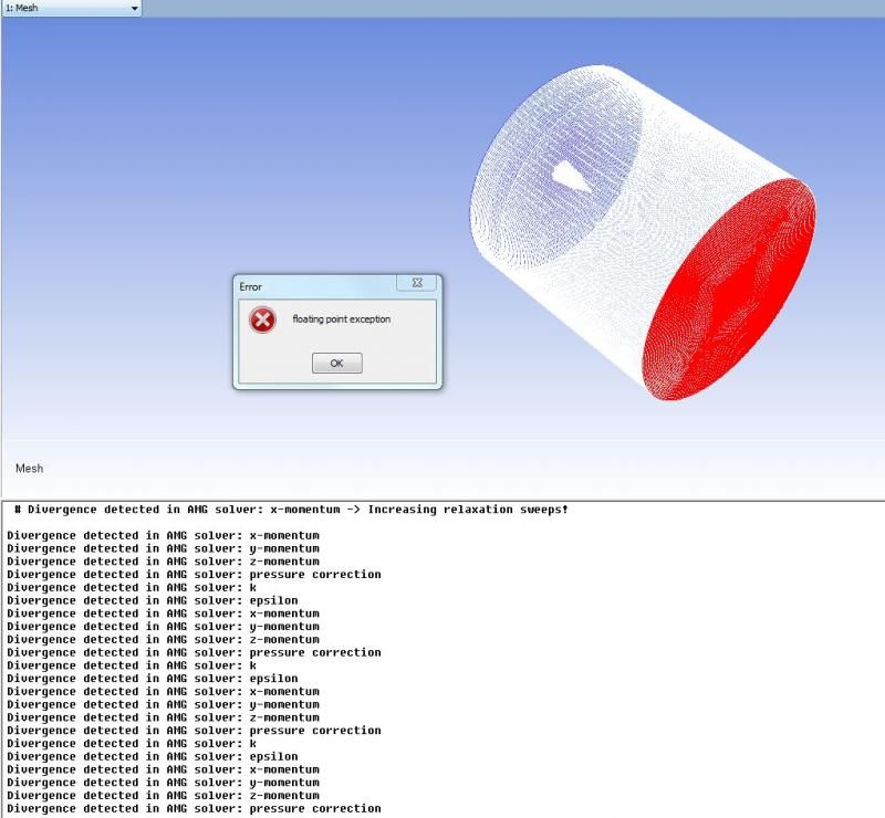
Добрый вечер, уважаемые форумчане. В общем, моделирую течение газа в аэродинамической установке — форкамера, сопло, рабочая часть. Все шло вполне себе гладко до сопла, позволяющего получать скорость потока порядка М=6. Подскажите, пожалуйста, о чем может говорить данная ошибка (картинка приложена ниже) и какими способами можно решить проблему. Потому что, ну, не может скорость при прохождении через критическое сечение сопла подниматься до нескольких десятков Махов. Рад любым мыслям, наводкам и подсказкам.
Go to CFD
r/CFD
r/CFD
Members
Online
•
by
PLANTAGENET123
Ansys Fluent: Float point exception error
I had an error of float point exception when doing simulation in Fluent. What does it means and how to avoid this errors.
How to… fix error Floating Point Exception -Overflow in Ansys CFX ?
Many times, during the implementation of numerical modeling, after completing the boundary and initial conditions and starting the solver we have to do with a sudden stop of the analysis and the appearance of an overflow message. This is the most common type of error that occurs when performing CFD analysis. In today’s post, I would like to present two paths to minimize the appearance of this error.
 |
| Most often error in CFX |
The first path will be the method most tested by me from the practical side. It was effective in many cases where I encountered an overflow error. The second path is the standard procedures to follow to get rid of this error. In my opinion, two approaches should be familiarized with to have a full spectrum of knowledge about this error. It’s written in such a general way by the solver, which makes it very difficult to diagnose directly.
To accurately describe and explain the first method, I will use an example of a modeling task. So our problem will be cooling process of the plate at a pressure of 5 bar. For this task, we will adopt the following assumptions: we will take into account the total energy model, we will define compressible air (ideal gas) as gas, we will define the SST turbulence model, we will take into account the radiation phenomenon by adopting the Surface to Surface model and that due to the symmetry of the model we will simplify the geometry to a periodic slice.
After defining the model phenomena, the time step was set at 1 s. Then solver was initiated. After couple of seconds simulation was stopped with an overflow error after seven iterations. What next steps should be taken to locate an analysis failure? Below I will present in order from the least labor-intensive to the most-labor-intensive activity.
1. Reduce the size of the time step. The best reduction ratio is 1:10 scale. So in our case we reduce the step from 1 s to 0.1 s. For transient analyzes, the definition of the correct time step size is much more important than the mesh quality. The residual equations are more responsive to the size of the time step than to the change of the grid size. In the case of static analyzes, we have such factors to change as the pseudo transient step or the time step of the solid domain. If the next reduction to 0.01 s has no effect, proceed to the next step.
2. Change the gas model from compressible to incompressible. This will cause our problem to reduce its nonlinearity. Do not be afraid of this simplification if your problem concerns low pressures and speeds. The differences in gas models in this case should not be large. If this modification also does not help, go to the next one.
3. If the above two points do not work in the next step, turn off the radiation model. This should greatly simplify the analysis and the partial equations will be less susceptible to mesh quality. Radiation models significantly extend the simulation time. A bad mesh may lead to the formation of non-physical temperature values (values greater than the assumed temperature in the boundary and initial conditions).
4) The next stage is to reduce the value of the assumed boundary and initial conditions. If in the analysis you have assumed a pressure of over 2 bar or values close to the phenomenon of vacuum, change this value to atmospheric pressure. Also, when it comes to temperature values (above 1200 C), reduce them by at least half. The same should be done for the initial speed (if you are analyzing high speeds over 150 m / s).
5) If all of the above steps fail, perform the last step. When you have defined symmetry or periodicity, try to do calculations for the entire model without these boundary conditions. It can be quite a laborious step requiring the reconstruction of the model, but it can bring measurable benefits in the implementation of the analysis.
After completing the above steps, if you still have a problem with the error overflow: floating point exception, try the next methods posted on the CFD Online website. Below is a link to these materials. It is worth reading the entire post because the information contained therein is extremely valuable.
Ansys FAQ — CFD-Wiki, the free CFD reference (cfd-online.com)
|
|
|
#1 |
|
New Member Shane Join Date: Aug 2014 Posts: 10 Rep Power: 10
|
I have been getting the same particular error ever since I’ve tried to run my mesh in Fluent. Initially, i thought it was because of a bad mesh and I’ve tried to improve the quality of my mesh as much as possible but I am still getting the same floating point error. Even reducing the under relaxation factor does not help. Would greatly appreciated if someone can give me some insights, I am truly lost as to what else to do. This is the full error message; # Divergence detected in AMG solver: x-momentum -> Increasing relaxation sweeps! Divergence detected in AMG solver: x-momentum Primitive Error at Node 2: floating point exception Primitive Error at Node 3: floating point exception Primitive Error at Node 0: floating point exception Error: floating point exception
|
|

|
|


|
|
|
#2 |
|
Member şakir Join Date: Mar 2012 Posts: 30 Rep Power: 13
|
Hi! I have same problem. Do you work parallel solver? |
|
|
|
|
|
|
|
#3 |
|
New Member Shane Join Date: Aug 2014 Posts: 10 Rep Power: 10
|
Yes I used parallel solver. I believe this has to do with my mesh having negative volume elements. |
|
|
|
|
|
|
|
#4 |
|
Member şakir Join Date: Mar 2012 Posts: 30 Rep Power: 13
|
I haven’t negative volume elements but i get same error. I think it is about parallel solver. |
|
|
|
|
|
|
|
#5 |
|
New Member Shane Join Date: Aug 2014 Posts: 10 Rep Power: 10
|
Have you been able to figure out the cause of this? It runs Ok in series? |
|
|
|
|
|
|
|
#6 |
|
Member şakir Join Date: Mar 2012 Posts: 30 Rep Power: 13
|
I have 28 species and wall reactions. So i couldn’t get serial solver.i only guess. |
|
|
|
|
|
|
|
#7 |
|
New Member Shane Join Date: Aug 2014 Posts: 10 Rep Power: 10
|
Is anyone able to help out with this issue? |
|
|
|
|
|
|
|
#8 |
|
Member Iman Join Date: Nov 2013 Posts: 37 Rep Power: 11
|
Quote:
Originally Posted by nyox Is anyone able to help out with this issue? Did you manage to identify the cause of the error? could you please share how you solved it? |
|
|
|
|

|
|
|
#9 |
|
New Member Dave M. Join Date: Aug 2014 Location: Koblenz, Germany Posts: 14 Rep Power: 10
|
Check your mesh quality for negative volumes, high aspect ratio and so on. Also check your boundary conditions — are they correctly set? |
|
|
|
|
|
|
|
#10 |
|
New Member Ali Mohammadi Join Date: Oct 2017 Posts: 15 Rep Power: 7
|
I faced the same problem and solved it. My domain is axisymmetric and i had not selected all the edges set as axis boundary.I selected the right edge and it disappeared. |
|
|
|
|
|
|
|
#11 |
|
New Member avpe Join Date: Nov 2015 Posts: 1 Rep Power: 0
|
Quote:
Originally Posted by cfd lover I faced the same problem and solved it. My domain is axisymmetric and i had not selected all the edges set as axis boundary.I selected the right edge and it disappeared. If you want to use a 2D axisymmetric model you have to set the geometry in an special way: The geomery have to be draw in the YX plane and in a way that the rotational axis folows the x direction. |
|
|
|
|
|
|
|
#12 |
|
Member Oula Join Date: Apr 2015 Location: United Kingdom Posts: 81 Rep Power: 10
|
Quote:
Originally Posted by cfd lover I faced the same problem and solved it. My domain is axisymmetric and i had not selected all the edges set as axis boundary.I selected the right edge and it disappeared. Hi cfd lover, was your geometry a 3D or 2D? |
|
|
|
|