Поиск ошибок и различных проблем. Поможем решить и исправить
Asus z97 pro коды ошибок
[Материнская плата] Возможные Q-CODE(коды ошибок) и их устранение
Пожалуйста, проверьте, поддерживает ваша плата Q-CODE или нет:
С помощью распространенных Q-CODE можно определить распрестраненные проблемы при установке компонентов в материнскую плату.
Пожалуйста, следуйте таблице Q-CODE ниже для устранения неисправности:
Распространенные Q-CODE
для плат на базе Intel
Распространенные Q-CODE
для плат на базе AMD
ошибка CPU
ошибка памяти
ошибка графической карты
Другое
00,D0
V
53,55
F9
V
D6
V
B0,99,15,53,
V
V
D6
V
V
00,19,30,40,55
V
V
V
A0,A2
A0,A2
Ненормальная загрузка устройства
B2
B2
Внешнее устройство работает неверно
A9
A9
Загрузка в BIOS
AA
AA
Загрузка в систему
Устранение неполадок с CPU
1. Войдите в ASUS Центр-загрузки для проверки совместимости вашей платы и процессора:
a. Введите наименование модели платы в поисковой строке (Например: ROG CROSSHAIR VII HERO), затем выберите ее из выпадающего меню и нажмите.
b. Пожалуйста, нажмите на [Поддержка Процессора/ Память], как показано ниже:
c. Кликните на [Поддержка процессоров] и проверьте, есть ваш CPU в списке совместимости QVL или нет, также проверьте версию BIOS рекомендуемую к установке (версия должна быть такой, как указана или новее).
2. Попробуйте переустановить CPU и проверьте контакты CPU на наличие грязи. Если они имеются, очистите контакты.
3. Проверьте CPU контакты на наличие повреждений. Если они имеются, пожалуйста, замените на новый процессор.
Устранение неисправности с памятью
1. Переустановите планку памяти, и убедитесь, что она подключена верно и до конца.
Неверная установка:
Верная установка:
2. Проверьте, не загрязнены ли контакты памяти или слот на материнской плате как показано ниже. Если да, очистите и попробуйте снова.
3. Если вы используете 2 и более планок, попробуйте подключить хотя бы одну планку и загрузитесь с ней. Если система запускается хотя бы с одной планкой памяти, попробуйте каждую из них по отдельности, чтобы выявить неисправную планку.
4. Предлагаемые конфигурации памяти смотрите в руководстве пользователя вашей модели, как показано на рисунке ниже, затем повторите попытку:
Можете воспользоваться ссылкой: Какс качать руководство
5. Если проблема не может быть решена после выполнения шагов 1–4, замените на заведомо исправную память и повторите попытку.
Устранение неполадок с графической картой
1. Интегрированная графика (встроенная) выходит из строя. Пожалуйста, попробуйте переустановить процессор
2. Неправильный вывод на экран дополнительной видеокарты:
a. Попробуйте переустановить видеокарту
b. Проверьте, нет ли грязи на контакте PCI-E материнской платы или контакте видеокарты, как показано на рисунке ниже. Если да, очистите их и попробуйте еще раз
c. Если внешняя графическая карта имеет интерфейс питания, убедитесь, что интерфейс питания правильно подключен, как показано ниже:
d. Если ваша проблема не может быть решена после выполнения шагов a ~ c, замените на исправную видеокарту и повторите попытку.
Устранение неполадок загрузки
1. Пожалуйста, повторно подключите кабель SATA к материнской плате и жесткому диску соответственно.
2. Если установлен M.2 SSD, снова подключите M.2 SSD и убедитесь, что винт M.2 заблокирован.
3. Проверьте, нет ли грязи на позолоченных контактах M.2 SSD или M.2 слота материнской платы, как показано на изображении ниже. Если обнаружена грязь, очистите контакты и попробуйте еще раз.
4. Если шаги 1–3 не могут решить вашу проблему, замените на исправный кабель SATA, порт SATA или жесткий диск SATA (M.2 SSD) и повторите попытку.
Устранение неполадок с внешними устройствами
1. Выключите питание и удалите все внешние устройства (например, карту PCI-E, карту Raid и т. д.) от материнской платы.
2. Затем попробуйте перезагрузить компьютер. Если он включается, проблема может быть в удаленных внешних устройствах. Повторно подключайте внешние устройства одно за другим, пока не обнаружите, какое внешнее устройство или кабель вызывает проблему.
Проблема загрузки в BIOS
Если CODE — A9, значит компьютер вошел в BIOS
1. Если монитор неисправен, выполните следующие действия для устранения неполадок:
a. Убедитесь, что монитор подключен правильно, и убедитесь, что световой индикатор монитора горит, что означает, что кабель питания монитора подключен правильно. Убедитесь, что внешний кабель питания подключен нормально. Пожалуйста, попробуйте включить, выключить, проверьте, может ли монитор отображать. Если вы выключаете и включаете монитор, на мониторе отображается «нет сигнала», это означает, что монитор подключен верно.
b. Убедитесь, что сигнальный кабель (VGA / DVI / HDMI / DisplayPort) правильно подключен к монитору, а также убедитесь, что другой конец сигнального кабеля подключен к выходу дисплея (видеокарта) компьютера. Попробуйте снова подключить кабель дисплея с двух сторон и убедитесь, что все контакты не погнуты.
c. Убедитесь, что изображение на мониторе правильное. Например, если он в настоящее время подключен к компьютеру через интерфейс HDMI, вы должны выбрать выход дисплея монитора как выход дисплея HDMI.
d. Замените кабель того же типа (VGA / DVI / HDMI / DisplayPort) для повторной проверки.
e. Подключите монитор к другому компьютеру и убедитесь, что монитор работает нормально, чтобы устранить проблему с монитором.
2. Если на мониторе отображается BIOS, следуйте инструкциям Устранение неполадок загрузки, проверьте жесткий диск или SSD на исправность.
Вопросы и ответы:
Q1.Как узнать, поддерживает плата Q-CODE или нет?
A1: Вы можете проверить следующие три варианта:
Вариант 1: проверьте наличие Q-кода на материнской плате, который обычно находится на левом верхнем или нижнем крае материнской платы, как показано на рисунке ниже:
Вариант 2. Войдите в ASUS Центр-загрузок, скачайте руководство пользователя и проверьте там ASUS Q-CODE
1) Нажмите на , затем введите название модели материнской платы (например, ROG MAXIMUS IX FORMULA), выберите название модели в выпадающем меню, как показано ниже:
2) Нажмите [Характеристики], найдите [Special Features]- [ASUS Q-Design], и проверьте, есть ли параметр [ASUS Q-CODE]
Вариант 3. Войдите в ASUS Центр-загрузок, скачайте руководство пользователя и проверьте там ASUS Q-CODE
Скачайте мануал
1) Введите название модели материнской платы (например, ROG CROSSHAIR VII HERO), затем выберите название модели в раскрывающемся списке, как показано ниже:
2) Нажмите [Руководства и документы]
3) Нажмите [Руководство пользователя], найдите User’s Manual(English, затем нажмите [СКАЧАТЬ]):
4) Найдите [Special Features] — [ASUS Q-Design], и проверьте [Q-CODE]
Q2: Что делать, если Qпроблема так и не решилась?
A2: Пожалуйста, попробуйте очистить CMOS, как это сделать описано тут: Как очистить CMOS
Если проблема по-прежнему не может быть устранена, свяжитесь с нами Служба поддержки
Code
Description
00
Not used
01
Power on. Reset type detection (soft/hard).
02
AP initialization before microcode loading
03
System Agent initialization before microcode loading
04
PCH initialization before microcode loading
06
Microcode loading
07
AP initialization after microcode loading
08
System Agent initialization after microcode loading
09
PCH initialization after microcode loading
0B
Cache initialization
0C – 0D
Reserved for future AMI SEC error codes
0E
Microcode not found
0F
Microcode not loaded
10
PEI Core is started
11 – 14
Pre-memory CPU initialization is started
15 – 18
Pre-memory System Agent initialization is started
19 – 1C
Pre-memory PCH initialization is started
2B – 2F
Memory initialization
30
Reserved for ASL (see ASL Status Codes section below)
31
Memory Installed
32 – 36
CPU post-memory initialization
37 – 3A
Post-Memory System Agent initialization is started
3B – 3E
Post-Memory PCH initialization is started
4F
DXE IPL is started
Memory initialization error. Invalid memory type or incompatible memory
50 – 53
speed
54
Unspecified memory initialization error
55
Memory not installed
56
Invalid CPU type or Speed
57
CPU mismatch
58
CPU self test failed or possible CPU cache error
59
CPU micro-code is not found or micro-code update is failed
ASUS Z87-PRO (V EDITION)
(continued on the next page)
1-33
Куратор(ы):
DKR
Автор
Сообщение
, затем введите название модели материнской платы (например, ROG MAXIMUS IX FORMULA), выберите название модели в выпадающем меню, как показано ниже:
2) Нажмите [Характеристики], найдите [Special Features]- [ASUS Q-Design], и проверьте, есть ли параметр [ASUS Q-CODE]
Вариант 3. Войдите в ASUS Центр-загрузок, скачайте руководство пользователя и проверьте там ASUS Q-CODE
Скачайте мануал
1) Введите название модели материнской платы (например, ROG CROSSHAIR VII HERO), затем выберите название модели в раскрывающемся списке, как показано ниже:
2) Нажмите [Руководства и документы]
3) Нажмите [Руководство пользователя], найдите User’s Manual(English, затем нажмите [СКАЧАТЬ]):
4) Найдите [Special Features] — [ASUS Q-Design], и проверьте [Q-CODE]
Q2: Что делать, если Qпроблема так и не решилась?
A2: Пожалуйста, попробуйте очистить CMOS, как это сделать описано тут: Как очистить CMOS
Если проблема по-прежнему не может быть устранена, свяжитесь с нами Служба поддержки
Пожалуйста, проверьте, поддерживает ваша плата Q-CODE или нет:
С помощью распространенных Q-CODE можно определить распрестраненные проблемы при установке компонентов в материнскую плату.
Пожалуйста, следуйте таблице Q-CODE ниже для устранения неисправности:
Распространенные Q-CODE
для плат на базе Intel
Распространенные Q-CODE
для плат на базе AMD
ошибка CPU
ошибка памяти
ошибка графической карты
Другое
00,D0
V
53,55
F9
V
D6
V
B0,99,15,53,
V
V
D6
V
V
00,19,30,40,55
V
V
V
A0,A2
A0,A2
Ненормальная загрузка устройства
B2
B2
Внешнее устройство работает неверно
A9
A9
Загрузка в BIOS
AA
AA
Загрузка в систему
Устранение неполадок с CPU
1. Войдите в ASUS Центр-загрузки для проверки совместимости вашей платы и процессора:
a. Введите наименование модели платы в поисковой строке (Например: ROG CROSSHAIR VII HERO), затем выберите ее из выпадающего меню и нажмите.
b. Пожалуйста, нажмите на [Поддержка Процессора/ Память], как показано ниже:
c. Кликните на [Поддержка процессоров] и проверьте, есть ваш CPU в списке совместимости QVL или нет, также проверьте версию BIOS рекомендуемую к установке (версия должна быть такой, как указана или новее).
2. Попробуйте переустановить CPU и проверьте контакты CPU на наличие грязи. Если они имеются, очистите контакты.
3. Проверьте CPU контакты на наличие повреждений. Если они имеются, пожалуйста, замените на новый процессор.
Устранение неисправности с памятью
1. Переустановите планку памяти, и убедитесь, что она подключена верно и до конца.
Неверная установка:
Верная установка:
2. Проверьте, не загрязнены ли контакты памяти или слот на материнской плате как показано ниже. Если да, очистите и попробуйте снова.
3. Если вы используете 2 и более планок, попробуйте подключить хотя бы одну планку и загрузитесь с ней. Если система запускается хотя бы с одной планкой памяти, попробуйте каждую из них по отдельности, чтобы выявить неисправную планку.
4. Предлагаемые конфигурации памяти смотрите в руководстве пользователя вашей модели, как показано на рисунке ниже, затем повторите попытку:
Можете воспользоваться ссылкой: Какс качать руководство
5. Если проблема не может быть решена после выполнения шагов 1–4, замените на заведомо исправную память и повторите попытку.
Устранение неполадок с графической картой
1. Интегрированная графика (встроенная) выходит из строя. Пожалуйста, попробуйте переустановить процессор
2. Неправильный вывод на экран дополнительной видеокарты:
a. Попробуйте переустановить видеокарту
b. Проверьте, нет ли грязи на контакте PCI-E материнской платы или контакте видеокарты, как показано на рисунке ниже. Если да, очистите их и попробуйте еще раз
c. Если внешняя графическая карта имеет интерфейс питания, убедитесь, что интерфейс питания правильно подключен, как показано ниже:
d. Если ваша проблема не может быть решена после выполнения шагов a ~ c, замените на исправную видеокарту и повторите попытку.
Устранение неполадок загрузки
1. Пожалуйста, повторно подключите кабель SATA к материнской плате и жесткому диску соответственно.
2. Если установлен M.2 SSD, снова подключите M.2 SSD и убедитесь, что винт M.2 заблокирован.
3. Проверьте, нет ли грязи на позолоченных контактах M.2 SSD или M.2 слота материнской платы, как показано на изображении ниже. Если обнаружена грязь, очистите контакты и попробуйте еще раз.
4. Если шаги 1–3 не могут решить вашу проблему, замените на исправный кабель SATA, порт SATA или жесткий диск SATA (M.2 SSD) и повторите попытку.
Устранение неполадок с внешними устройствами
1. Выключите питание и удалите все внешние устройства (например, карту PCI-E, карту Raid и т. д.) от материнской платы.
2. Затем попробуйте перезагрузить компьютер. Если он включается, проблема может быть в удаленных внешних устройствах. Повторно подключайте внешние устройства одно за другим, пока не обнаружите, какое внешнее устройство или кабель вызывает проблему.
Проблема загрузки в BIOS
Если CODE — A9, значит компьютер вошел в BIOS
1. Если монитор неисправен, выполните следующие действия для устранения неполадок:
a. Убедитесь, что монитор подключен правильно, и убедитесь, что световой индикатор монитора горит, что означает, что кабель питания монитора подключен правильно. Убедитесь, что внешний кабель питания подключен нормально. Пожалуйста, попробуйте включить, выключить, проверьте, может ли монитор отображать. Если вы выключаете и включаете монитор, на мониторе отображается «нет сигнала», это означает, что монитор подключен верно.
b. Убедитесь, что сигнальный кабель (VGA / DVI / HDMI / DisplayPort) правильно подключен к монитору, а также убедитесь, что другой конец сигнального кабеля подключен к выходу дисплея (видеокарта) компьютера. Попробуйте снова подключить кабель дисплея с двух сторон и убедитесь, что все контакты не погнуты.
c. Убедитесь, что изображение на мониторе правильное. Например, если он в настоящее время подключен к компьютеру через интерфейс HDMI, вы должны выбрать выход дисплея монитора как выход дисплея HDMI.
d. Замените кабель того же типа (VGA / DVI / HDMI / DisplayPort) для повторной проверки.
e. Подключите монитор к другому компьютеру и убедитесь, что монитор работает нормально, чтобы устранить проблему с монитором.
2. Если на мониторе отображается BIOS, следуйте инструкциям Устранение неполадок загрузки, проверьте жесткий диск или SSD на исправность.
Вопросы и ответы:
Q1.Как узнать, поддерживает плата Q-CODE или нет?
A1: Вы можете проверить следующие три варианта:
Вариант 1: проверьте наличие Q-кода на материнской плате, который обычно находится на левом верхнем или нижнем крае материнской платы, как показано на рисунке ниже:
Вариант 2. Войдите в ASUS Центр-загрузок, скачайте руководство пользователя и проверьте там ASUS Q-CODE
1) Нажмите на , затем введите название модели материнской платы (например, ROG MAXIMUS IX FORMULA), выберите название модели в выпадающем меню, как показано ниже:
2) Нажмите [Характеристики], найдите [Special Features]- [ASUS Q-Design], и проверьте, есть ли параметр [ASUS Q-CODE]
Вариант 3. Войдите в ASUS Центр-загрузок, скачайте руководство пользователя и проверьте там ASUS Q-CODE
Скачайте мануал
1) Введите название модели материнской платы (например, ROG CROSSHAIR VII HERO), затем выберите название модели в раскрывающемся списке, как показано ниже:
2) Нажмите [Руководства и документы]
3) Нажмите [Руководство пользователя], найдите User’s Manual(English, затем нажмите [СКАЧАТЬ]):
4) Найдите [Special Features] — [ASUS Q-Design], и проверьте [Q-CODE]
Q2: Что делать, если Qпроблема так и не решилась?
A2: Пожалуйста, попробуйте очистить CMOS, как это сделать описано тут: Как очистить CMOS
Если проблема по-прежнему не может быть устранена, свяжитесь с нами Служба поддержки
Code
Description
00
Not used
01
Power on. Reset type detection (soft/hard).
02
AP initialization before microcode loading
03
System Agent initialization before microcode loading
04
PCH initialization before microcode loading
06
Microcode loading
07
AP initialization after microcode loading
08
System Agent initialization after microcode loading
09
PCH initialization after microcode loading
0B
Cache initialization
0C – 0D
Reserved for future AMI SEC error codes
0E
Microcode not found
0F
Microcode not loaded
10
PEI Core is started
11 – 14
Pre-memory CPU initialization is started
15 – 18
Pre-memory System Agent initialization is started
19 – 1C
Pre-memory PCH initialization is started
2B – 2F
Memory initialization
30
Reserved for ASL (see ASL Status Codes section below)
31
Memory Installed
32 – 36
CPU post-memory initialization
37 – 3A
Post-Memory System Agent initialization is started
3B – 3E
Post-Memory PCH initialization is started
4F
DXE IPL is started
Memory initialization error. Invalid memory type or incompatible memory
50 – 53
speed
54
Unspecified memory initialization error
55
Memory not installed
56
Invalid CPU type or Speed
57
CPU mismatch
58
CPU self test failed or possible CPU cache error
59
CPU micro-code is not found or micro-code update is failed
ASUS Z87-PRO (V EDITION)
(continued on the next page)
1-33
Куратор(ы):
DKR
Автор
Сообщение
Добавлено: 13.06.2013 8:13
[профиль]
Junior
Статус: Не в сети Регистрация: 01.01.2011
Обсуждение материнских плат ASUS на чипсете Z87/Z97 и всё, что с ними связано.
========#77……………FAQ……………#77========
Также необходимо ознакомиться с темами:
Процессоры Intel семейства Core i3/i5/i7 (микроархитектура Haswell)
Методика тестирования и определение стабильности при разгоне процессоров Intel. FAQ на первой странице.
Температура процессоров Intel (FAQ — стр.1)
FAQ: Какой процессор будет оптимальным для моих задач? (часть 2)
Выбор матплаты LGA1150
Выбор оперативной памяти DDR III для Intel.
Если у вас не запускается процессор Devil’s Canyon (i5-4690k/i7-4790k) на материнской плате с чипсетом Z87/H81/H87/B85, нужно прошить последнюю версию BIOS из-под Windows через утилиту BIOS Updater (не через Asus EZ Flash Utility). Подробнее см. FAQ темы
Уважаемые друзья, при общении соблюдаемПравила конференции
Последний раз редактировалось jjxaker 04.05.2014 23:10, всего редактировалось 19 раз(а).
Реклама
Партнер
jjxaker
Member
Статус: Не в сети Регистрация: 18.02.2008 Фото: 0
Genrix писал(а):
Как мне сделать, чтобы дискретки пользовались в играх, а iGPU во все остальное время? Это возможно?
да, Virtu MVP2.0 ввели поддержку Haswell
http://www.lucidlogix.com/eshop.shtml
но тут такое дело что на z87 нет лицензии так что платить нужно ну или сам понимаешь ломать 600% faster GPU покупаем
Genrix
Member
Статус: Не в сети Регистрация: 25.01.2004 Откуда: Ростов-на-Дону Фото: 4
jjxaker Для этой Virtu MVP2.0 мне надо чип на матери этот? У меня нет его. Я в пролете?
Еще есть такая мысль. У меня монитор это плазма 42″ и у нее два входа HDMI, а что если кинуть два кабеля и сказать системе что у меня типа два монитора и щелкать с пульта входы? Хотелось бы, чтобы дискретки вне игр сильнее спали…. ( в идеале выключались, но мне кажется они этого не умеют).
_________________ 12400|224XT|MSI PRO B660M-A DDR4|2x8Gb@3200|MSI Armor GTX1060-6|Deepcool PQ650M|Corsair 200R|Win10x64
jjxaker
Member
Статус: Не в сети Регистрация: 18.02.2008 Фото: 0
Genrix писал(а):
Для этой Virtu MVP2.0 мне надо чип на матери этот?
не, это софтовая преблуда.
Genrix писал(а):
Еще есть такая мысль.
не выйдет того что ты задумал.
Genrix писал(а):
Хотелось бы, чтобы дискретки вне игр сильнее спали
включи ASPM для северного моста, а для южного моста лучше выключай для минимизации глюков. в биосе ASPM разделяется на SB и NB, и с PCI Express Native Power Management поиграйся.
nightman-
Member
Статус: Не в сети Регистрация: 07.01.2012
jjxaker писал(а):
а как же: вот мануал
Ага, спасибо, видимо пока выпуская такую продукцию они смогут курить траву завернутую во франклины ничего не изменится.
_________________ QTJ1@5.0 • Apex IX • Liquid Freezer II 420mm • CruBall 2x16Gb@3000• GTX1070 OC • 970 Evo Plus 1Tb • CM Storm Trooper • Silencer MK III 850w • HP X34
Ironman
Member
Статус: Не в сети Регистрация: 08.12.2011
друзья, в Москве никто не видел в продаже платы степпинга c2? в частности интересует asus z87-pro
_________________ Юрист широкого профиля!
proto_typ
Junior
Статус: Не в сети Регистрация: 23.09.2013
SOS! Первая попытка сборки компа! При включении выдает код d7+звуковой сигнал, через 3-4 сек. код АЕ. Я в железе: почти 0. Но оч.хоца понять! i5-4670K, ASUS Z87-PRO
vasilii2040
Member
Статус: Не в сети Регистрация: 07.09.2013 Откуда: Казахстан Фото: 11
proto_typ писал(а):
код АЕ
AE это проблемы с загрузочным диском, кмос сбрасывал? D7 Переход процессора в режим энергосбережения с использованием технологии APM Что за проц и какой биос?) Коды и диагностические сообщения POST BIOS различных компаний
Спасибо за ответ! Проц: i5-4670k. Мать: Z87-PRO. БИОС: АМИ, версия: ХЗ! после сброса кмос: код по Q-POST материнки: 99 и ни каких звуков! По классификации на АМИ БИОС такого кода нет!
vasilii2040
Member
Статус: Не в сети Регистрация: 07.09.2013 Откуда: Казахстан Фото: 11
proto_typ писал(а):
Спасибо за ответ! Проц: i5-4670k. Мать: Z87-PRO. БИОС: АМИ, версия: ХЗ! после сброса кмос: код по Q-POST материнки 99 и ни каких звуков!
Вот выход из положения твоего, должен помочь. Обновляй биос через Flashback. Используйте флешку с FAT32. Скачай, новую версию биоса вот ссылка
распакуй и закинь на флешку в корень файл с расширением .cap. Подключи флешку к порту USB flahback (тот что обычно выделен белым цветом и находится рядом с кнопкой bios). Не запускай комп, просто проверь, что источник питания включен и кабели питания. Нажми кнопку BIOS в заде на понели, и держим в течении 3/5 секунд пока не начнет мигать она, затем жди пока индикатор потухнет. И перед всей этой манипуляцией еще раз скин кмос по дефалту.
_________________ БЫСТРЕЕ, ХОЛОДНЕЕ, ТИШЕ ! ! !
Borobor
Member
Статус: Не в сети Регистрация: 08.05.2008
На z87-pro нужный usb порт это нижний под LAN портом.
proto_typ
Junior
Статус: Не в сети Регистрация: 23.09.2013
vasilii2040 писал(а):
Вот выход из положения твоего, должен помочь. Обновляй биос через Flashback. Используйте флешку с FAT32. Скачай, новую версию биоса вот ссылка
http://www.asus.com/ru/Motherboards/Z87
… ownload_10 распакуй и закинь на флешку в корень файл с расширением .cap. Подключи флешку к порту USB flahback (тот что обычно выделен белым цветом и находится рядом с кнопкой bios). Не запускай комп, просто проверь, что источник питания включен и кабели питания. Нажми кнопку BIOS в заде на понели, и держим в течении 3/5 секунд пока не начнет мигать она, затем жди пока индикатор потухнет. И перед всей этой манипуляцией еще раз скин кмос по дефалту.
Кнопку на материнке BIOS_FLBK?
proto_typ
Junior
Статус: Не в сети Регистрация: 23.09.2013
Borobor писал(а):
Да
Нажал! Жду! Как долго? и какие действия дальше?
vasilii2040
Member
Статус: Не в сети Регистрация: 07.09.2013 Откуда: Казахстан Фото: 11
proto_typ писал(а):
Нажал! Жду! Как долго? и какие действия дальше?
ждём пока индикатор потухнет затем запускаем машину, заходим сразу в биос и нажимаем F5 потом F10 если все тип топ то уже патом настраиваешь биос как угодно. Если после 5 секунд мигания индикация перейдёт в постоянное свечение — значит функция не работает должным образом, это возникает по причине: 1) Неправильно подготовленной флешки 2) Неправильного имени файла биоса или неподдерживаемого формата файла. Если произошла данная ситуация — перезагрузите систему(либо передёрните питание), чтобы сбросить функцию Flashback.
_________________ БЫСТРЕЕ, ХОЛОДНЕЕ, ТИШЕ ! ! !
proto_typ
Junior
Статус: Не в сети Регистрация: 23.09.2013
vasilii2040 писал(а):
ждём пока индикатор потухнет затем запускаем машину, заходим сразу в биос и нажимаем F5 потом F10 если все тип топ то уже патом настраиваешь биос как угодно. Если после 5 секунд мигания индикация перейдёт в постоянное свечение — значит функция не работает должным образом, это возникает по причине: 1) Неправильно подготовленной флешки 2) Неправильного имени файла биоса или неподдерживаемого формата файла. Если произошла данная ситуация — перезагрузите систему(либо передёрните питание), чтобы сбросить функцию Flashback.
Горит -не тухнет! Флешка: FAT32 Файл: из архива по ссылке (Z87-PRO BIOS 1405 Improve system stability. Делал все как описано тобою выше. После перезапуска системы: код 99+1″бип» и тишина! На плате горит красный led «boot_device» Кулер молотит. на видюхе возле разъема питания горит зел.»led1″. НDD походу в работе. Привод тоже!
Последний раз редактировалось proto_typ 23.09.2013 22:04, всего редактировалось 1 раз.
vasilii2040
Member
Статус: Не в сети Регистрация: 07.09.2013 Откуда: Казахстан Фото: 11
у тебя случаенно не Z87PRO(V_EDITION)
_________________ БЫСТРЕЕ, ХОЛОДНЕЕ, ТИШЕ ! ! !
Moe
Member
Статус: Не в сети Регистрация: 29.02.2012
Вытащить все из корпуса и собрать на столе с минимум комплектующих. Проще говоря проц и память.
proto_typ
Junior
Статус: Не в сети Регистрация: 23.09.2013
vasilii2040 писал(а):
у тебя случаенно не Z87PRO(V_EDITION)
на плате просто Z87PRO
vasilii2040
Member
Статус: Не в сети Регистрация: 07.09.2013 Откуда: Казахстан Фото: 11
Переименуй название биоса Z87-PRO BIOS 1405.CAP на H87P.CAP и повтори все тоже самое. ту бли уже крыша едет не H87P a Z87P
_________________ БЫСТРЕЕ, ХОЛОДНЕЕ, ТИШЕ ! ! !
proto_typ
Junior
Статус: Не в сети Регистрация: 23.09.2013
Moe писал(а):
Вытащить все из корпуса и собрать на столе с минимум комплектующих. Проще говоря проц и память.
Монитор подключать?
—
Вы не можете начинать темы Вы не можете отвечать на сообщения Вы не можете редактировать свои сообщения Вы не можете удалять свои сообщения Вы не можете добавлять вложения
Лаборатория
Новости
Contents
Table of Contents
Bookmarks
Quick Links
Z87-PRO
(V EDITION)
IMPORTANT:
The Wi-Fi and Bluetooth hardware
module is not available on this
motherboard model.
Related Manuals for Asus Z87-PRO V EDITION
Summary of Contents for Asus Z87-PRO V EDITION
Page 1 Z87-PRO (V EDITION) IMPORTANT: The Wi-Fi and Bluetooth hardware module is not available on this motherboard model.
Page 2 Product warranty or service will not be extended if: (1) the product is repaired, modified or altered, unless such repair, modification of alteration is authorized in writing by ASUS; or (2) the serial number of the product is defaced or missing.
Page 3: Table Of Contents
Product highlights……………. 1-1 1.1.2 Dual Intelligent Processors 4 with 4-Way Optimization ….1-2 1.1.3 ASUS Exclusive Features …………1-3 1.1.4 ASUS Quiet Thermal Solution …………. 1-4 1.1.5 ASUS EZ DIY …………….1-4 1.1.6 Other special features …………..1-5 Motherboard overview …………….1-6 1.2.1…
Page 4 3.6.9 Network Stack …………….3-38 Monitor menu ………………. 3-39 Boot menu ………………..3-42 Tools menu ………………..3-48 3.9.1 ASUS EZ Flash 2 Utility …………3-48 3.9.2 ASUS O.C. Profile …………..3-48 3.9.3 ASUS SPD Information …………. 3-49 3.10 Exit menu ………………..3-50 3.11…
Page 5 Creating a RAID driver disk without entering the OS ….5-7 5.2.2 Creating a RAID driver disk in Windows ……..5-8 ® 5.2.3 Installing the RAID driver during Windows OS installation ..5-8 ® Appendices Notices ……………………A-1 ASUS contact information ………………A-5…
Page 6: Safety Information
Safety information Electrical safety • To prevent electrical shock hazard, disconnect the power cable from the electrical outlet before relocating the system. • When adding or removing devices to or from the system, ensure that the power cables for the devices are unplugged before the signal cables are connected. If possible, disconnect all power cables from the existing system before you add a device.
Page 7: About This Guide
Refer to the following sources for additional information and for product and software updates. ASUS websites The ASUS website provides updated information on ASUS hardware and software products. Refer to the ASUS contact information. Optional documentation Your product package may include optional documentation, such as warranty flyers, that may have been added by your dealer.
Page 8: Conventions Used In This Guide
Conventions used in this guide To ensure that you perform certain tasks properly, take note of the following symbols used throughout this manual. DANGER/WARNING: Information to prevent injury to yourself when trying to complete a task. CAUTION: Information to prevent damage to the components when trying to complete a task IMPORTANT: Instructions that you MUST follow to complete a task.
Page 9: Z87-Pro (V Edition) Specifications Summary
Z87-PRO (V EDITION) specifications summary LGA1150 socket for the 4th Generation Intel Core™ i7/Intel ® ® Core™i5/ Intel Core™ i3, Pentium and Celeron processors ® ® ® Supports 22nm CPU Supports Intel Turbo Boost Technology 2.0* ® * The Intel Turbo Boost Technology 2.0 support depends on the CPU ®…
Page 10 — Supports jack-detection, multi-streaming and front panel jack- retasking — Optical S/PDIF out ports at rear I/O Intel Z87 Express Chipset — supports ASUS USB 3.0 ® Boost — 2 x USB 3.0/2.0 ports at mid-board for front panel support — 2 x USB 3.0/2.0 ports at rear panel (blue)
Page 11 — ASUS Fan Xpert 2 — ASUS Fanless Design: Heat-sink solution ASUS EZ DIY — ASUS USB BIOS Flashback with USB BIOS Flashback Wizard for EZ BIOS download scheduling — ASUS UEFI BIOS EZ Mode featuring friendly graphics user interface — ASUS O.C.
Page 12 SFS (Stepless Frequency Selection) — BCLK��PCIE frequency tuning from �0MHz up to 300MHz at 0.1MHz increment Overclocking Protection — ASUS C.P.R.(CPU Parameter Recall) Rear Panel I/O Ports 1 x PS/2 Keyboard/mouse combo port 1 x DisplayPort 1 x HDMI port…
Page 13 BIOS features 64 Mb Flash ROM, UEFI AMI BIOS, PnP, DMI2.7, WfM2.0, SM BIOS 2.7, ACPI 5.0, Multi-language BIOS, ASUS EZ Flash 2, ASUS CrashFree BIOS 3, My Favorites, Quick Note, Last Modified log, F12 PrintScreen, F3 Shortcut functions, and ASUS DRAM SPD…
Page 14: Package Contents
If any of the above items is damaged or missing, contact your retailer. • The illustrated items above are for reference only. Actual product specifications may vary with different models. • The 1 x 2-in-1 ASUS Q-Connector kit is for retailer version only.
Page 15: Installation Tools And Components
Installation tools and components 1 bag of screws Philips (cross) screwdriver PC chassis Power supply unit Intel LGA1150 CPU Intel LGA1150 compatible CPU Fan ® ® DIMM SATA hard disk drive SATA optical disc drive (optional) Graphics card (optional) The tools and components in the table above are not included in the motherboard package.
Page 17: Chapter 1: Product Introduction
3D graphics, multimedia and Internet applications. Quad-GPU SLI and CrossFireX™ Support This motherboard features the most powerful Intel Z�7 platform that optimizes PCIe ® allocation in multi-GPU SLI and CrossFireX™ solution, giving you a brand-new gaming enjoyment. ASUS Z87-PRO (V EDITION)
Page 18: Dual Intelligent Processors 4 With 4-Way Optimization
1.1.2 Dual Intelligent Processors 4 with 4-Way Optimization ASUS Dual Intelligent Processors 4 brings system control solution to a totally whole new level, combining TPU, EPU, DIGI+ Power Control and Fan Xpert 2 functions to push the system’s performance to its optimal potential. It automatically pushes or reasonably balances the system’s performance, power saving levels and fan settings via the user-friendly AI Suite…
Page 19: Asus Exclusive Features
ASUS Exclusive Features USB 3.0 Boost ASUS USB 3.0 Boost, which supports USB 3.0 standard UASP (USB Attached SCSI Protocol), significantly increases a USB device’s transfer speed up to 170% faster than the already impressive USB 3.0 transfer speed. It automatically accelerates data speeds for compatible USB 3.0 peripherals without the need for any user interaction.
Page 20: Asus Quiet Thermal Solution
The heatsink design also lowers the temperature of the chipset and power phase area through high efficient heat-exchange. Combined with usability and aesthetics, the ASUS stylish heatsink will give you an extremely silent and cooling experience with its elegant appearance.
Page 21: Other Special Features
ASUS Q-connector ASUS Q-Connector is a unique adapter that allows you to easily connect or disconnect the chassis front panel cables to one module, eliminating the hassle of plugging one cable at a time and making the connection quick and accurate.
Page 22: Motherboard Overview
Motherboard overview 1.2.1 Before you proceed Take note of the following precautions before you install motherboard components or change any motherboard settings. • Unplug the power cord from the wall socket before touching any component. • Before handling components, use a grounded wrist strap or touch a safely grounded object or a metal object, such as the power supply case, to avoid damaging them due to static electricity.
Page 23: Motherboard Layout
1.2.2 Motherboard layout Refer to 1.2.8 Internal connectors and 2.3.1 Rear I/O connection for more information about rear panel connectors and internal connectors. ASUS Z87-PRO (V EDITION)
Page 24: Layout Contents
Layout contents Connectors/Jumpers/Slots Page 1. ATX power connectors (24-pin EATXPWR, 8-pin EATX12V) 1-44 2. LGA1150 CPU socket 3. CPU, chassis, and power fan connectors (4-pin CPU_FAN, 4-pin 1-42 CPU_OPT, 4-pin CHA_FAN1-4 ) 4. DDR3 DIMM slots 1-10 5. MemOK! button 1-26 6.
Page 25: Central Processing Unit (Cpu)
Contact your retailer immediately if the PnP cap is missing, or if you see any damage to the PnP cap/socket contacts/motherboard components. ASUS will shoulder the cost of repair only if the damage is shipment/ transit-related.
Page 26: System Memory
1.2.4 System memory The motherboard comes with four Double Data Rate 3 (DDR3) Dual Inline Memory Modules (DIMM) slots. A DDR3 module is notched differently from a DDR or DDR2 module. DO NOT install a DDR or DDR2 memory module to the DDR3 slot. Recommended memory configurations Chapter 1: Product introduction 1-10…
Page 27: Memory Configurations
Always install the DIMMS with the same CAS Latency. For an optimum compatibility, we recommend that you install memory modules of the same version or data code (D/ C) from the same vendor. Check with the vendor to get the correct memory modules. ASUS Z87-PRO (V EDITION) 1-11…
Page 37 • • Mach Xtreme MXD3U1333 16GQ 16GB (4x4GB) • • • Mach Xtreme MXD3V1333 2GS Mach C2S46D30- • • • Xtreme D313 MICRON MT8JTF25664AZ- MICRON D9PFJ • • • 1G4M1 (continued on the next page) ASUS Z87-PRO (V EDITION) 1-21…
Page 38 Hyper DIMM support is subject to the physical characteristics of individual CPUs. Load the X.M.P. or D.O.C.P. settings in the BIOS for the hyper DIMM support. • Visit the ASUS website for the latest QVL. Chapter 1: Product introduction 1-22…
Page 40 PCIe Express 3.0 operating mode VGA configuration PCIe 3.0/2.0 x16_1 PCIe 3.0/2.0 x16_2 x16 (single VGA Single VGA/PCIe card recommended) Dual VGA/PCIe card • We recommend that you provide sufficient power when running CrossFireX™ or SLI™ mode. • Connect a chassis fan to the motherboard connector labeled CHA_FAN1-4 when using multiple graphics cards for better thermal environment.
Page 41: Onboard Buttons And Switches
The button also lights up when the system is plugged to a power source indicating that you should shut down the system and unplug the power cable before removing or installing any motherboard component. ASUS Z87-PRO (V EDITION) 1-25…
Page 42: Memok! Switch
BIOS has been restored to its default settings. • We recommend that you download and update to the latest BIOS version from the ASUS website at www.asus.com after using the MemOK! function. Chapter 1: Product introduction 1-26…
Page 43 Turn off your system using the power-on button to allow your system to go through POST (without entering the BIOS) when you reboot your system. • Refer to section 3.8 Boot Menu for details about setting the DirectKey default function. ASUS Z87-PRO (V EDITION) 1-27…
Page 44 TPU switch With its two-level adjustment functions, the TPU allows you to automatically adjusts the CPU ratio and clock speed for an optimal system performance. • Enable this switch when the system is powered off. • When the TPU switch is set to Enabled (TPU_I: CPU Ratio Boost), the system automatically adjusts the CPU ratio for an enhanced performance.
Page 45 • You may change the EPU settings in the software application or BIOS setup program and enable the EPU function at the same time. However, the system will use the last setting you have made. ASUS Z87-PRO (V EDITION) 1-29…
Page 46: Jumper
1.2.7 Jumper Clear RTC RAM (3-pin CLRTC) This jumper allows you to clear the Real Time Clock (RTC) RAM in CMOS. You can clear the CMOS memory of date, time, and system setup parameters by erasing the CMOS RTC RAM data.
Page 47: Onboard Leds
(Power-On-Self Test): CPU, memory modules, VGA card, and hard disk drive.s If an error is found, the critical component’s LED stays lit up until the problem is solved. TPU LED The TPU LED lights up when the TPU switch is enabled. ASUS Z87-PRO (V EDITION) 1-31…
Page 48 EPU LED The EPU LED lights up when the EPU switch is enabled. Q-Code LED The Q-Code LED design provides you with a 2-digi error code that displays the system status. Refer to the Q-Code table on the next page for details. Chapter 1: Product introduction 1-32…
Page 49: Q-Code Table
Unspecified memory initialization error Memory not installed Invalid CPU type or Speed CPU mismatch CPU self test failed or possible CPU cache error CPU micro-code is not found or micro-code update is failed (continued on the next page) ASUS Z87-PRO (V EDITION) 1-33…
Page 50 Code Description Internal CPU error Reset PPI is not available 5C – 5F Reserved for future AMI error codes S3 Resume is stared (S3 Resume PPI is called by the DXE IPL) S3 Boot Script execution Video repost OS S3 wake vector call E4 –…
Page 51 9E – 9F Reserved for future AMI codes IDE initialization is started IDE Reset IDE Detect IDE Enable SCSI initialization is started SCSI Reset SCSI Detect SCSI Enable Setup Verifying Password (continued on the next page) ASUS Z87-PRO (V EDITION) 1-35…
Page 52 Code Description Start of Setup Reserved for ASL (see ASL Status Codes section below) Setup Input Wait Reserved for ASL (see ASL Status Codes section below) Ready To Boot event Legacy Boot event Exit Boot Services event Runtime Set Virtual Address MAP Begin Runtime Set Virtual Address MAP End Legacy Option ROM Initialization System Reset…
Page 53 System is waking up from the S3 sleep state System is waking up from the S4 sleep state System has transitioned into ACPI mode. Interrupt controller is in PIC mode. System has transitioned into ACPI mode. Interrupt controller is in APIC mode. ASUS Z87-PRO (V EDITION) 1-37…
Page 54: Internal Connectors
1.2.9 Internal connectors Intel Z87 Serial ATA 6.0 Gb/s connectors (7-pin SATA6G_1-6 [yellow]) ® These connectors connect to Serial ATA 6.0 Gb/s hard disk drives via Serial ATA 6.0 Gb/s signal cables. If you installed Serial ATA hard disk drives, you can create a RAID 0, 1, 5, and 10 configuration with the Intel Rapid Storage Technology through the onboard Intel ®…
Page 55 This connector is for an additional Sony/Philips Digital Interface (S/PDIF) port. Connect the S/PDIF Out module cable to this connector, then install the module to a slot opening at the back of the system chassis. The S/PDIF module is purchased separately. ASUS Z87-PRO (V EDITION) 1-39…
Page 56 USB 3.0 connector (20-1 pin USB3_12) This connector allows you to connect a USB 3.0 module for additional USB 3.0 front or rear panel ports. With an installed USB 3.0 module, you can enjoy all the benefits of USB 3.0 including faster data transfer speeds of up to 5Gbps, faster charging time for USB-chargeable devices, optimized power efficiency, and backward compatibility with USB 2.0.
Page 57 DO NOT connect a 1394 cable to the USB connectors. Doing so will damage the motherboard! You can connect the front panel USB cable to the ASUS Q-Connector (USB, dark brown) first, and then install the Q-Connector (USB) to the USB connector onboard if your chassis supports front panel USB ports.
Page 58 Ensure that the CPU fan is securely installed to the CPU fan connector. • The CPU_FAN connector supports the CPU fan of maximum 1A (12 W) fan power. • The CPU_FAN connector and CHA_FAN connectors support the ASUS FAN Xpert 2 feature. Chapter 1: Product introduction 1-42…
Page 59 • If you want to connect a high-definition or an AC’97 front panel audio module to this connector, set the Front Panel Type item in the BIOS setup to [HD] or [AC97]. ASUS Z87-PRO (V EDITION) 1-43…
Page 60 1000W power or above to ensure the system stability. • If you are uncertain about the minimum power supply requirement for your system, refer to the Recommended Power Supply Wattage Calculator at http://support.asus. com/PowerSupplyCalculator/PSCalculator.aspx?SLanguage=en-us for details. Chapter 1: Product introduction…
Page 61: System Panel Connector
Pressing the power switch for more than four seconds while the system is ON turns the system OFF. • Reset button (2-pin RESET) This 2-pin connector is for the chassis-mounted reset button for system reboot without turning off the system power. ASUS Z87-PRO (V EDITION) 1-45…
Page 62 TPM connector (20-1 pin TPM) This connector supports a Trusted Platform Module (TPM) system, which securely store keys, digital certificates, passwords and data. A TPM system also helps enhance network security, protect digital identities, and ensures platform integrity. Direct Connector (2-pin DRCT) This connector is for the chassis-mounted button that supports the DirectKey function.
Page 63: Chapter 2: Basic Installation
The diagrams in this section are for reference only. The motherboard layout may vary with models, but the installation steps are the same for all models. Install the ASUS I/O Shield to the chassis rear I/O panel. Place the motherboard into the chassis, ensuring that its rear I/O ports are aligned to the chassis’…
Page 64 Place nine screws into the holes indicated by circles to secure the motherboard to the chassis. DO NOT overtighten the screws! Doing so can damage the motherboard. Chapter 2: Basic installation…
Page 65: Cpu Installation
2.1.2 CPU installation Ensure that you install the correct CPU designed for LGA1150 socket only. DO NOT install a CPU designed for LGA155 and LGA1156 socket on the LGA1150 socket. ASUS Z87-PRO (V EDITION)
Page 66: Cpu Heatsink And Fan Assembly Installation
2.1.3 CPU heatsink and fan assembly installation Apply the Thermal Interface Material to the CPU heatsink and CPU before you install the heatsink and fan, if necessary. To install the CPU heatsink and fan assembly Chapter 2: Basic installation…
Page 67 To uninstall the CPU heatsink and fan assembly ASUS Z87-PRO (V EDITION)
Page 68: Dimm Installation
2.1.4 DIMM installation To remove a DIMM Chapter 2: Basic installation…
Page 69: Atx Power Connection
2.1.5 ATX Power connection ASUS Z87-PRO (V EDITION)
Page 70: Sata Device Connection
2.1.6 SATA device connection Chapter 2: Basic installation…
Page 71: Front I/O Connectors
2.1.7 Front I/O Connectors To install ASUS Q-Connector To install USB 2.0 connector To install front panel audio connector AAFP USB 2.0 To install USB 3.0 connector USB 3.0 ASUS Z87-PRO (V EDITION)
Page 72: Expansion Card Installation
2.1.8 Expansion Card installation To install PCIe x16 cards To install PCIe x1 cards Chapter 2: Basic installation 2-10…
Page 73: Bios Update Utility
Press the BIOS Flashback button for three seconds until a flashing light appears, which indicates that the BIOS Flashback function is enabled. Wait until the light goes out, indicating that the BIOS updating process is completed. ASUS Z87-PRO (V EDITION) 2-11…
Page 74 BIOS file name error, or incompatible BIOS file format. If this happens, restart the syetem. BIOS updating poses some risks. If the BIOS program is damaged during the updating process and the system fails to reboot, please contact your local ASUS Service Center for assistance Chapter 2: Basic installation…
Page 75: Motherboard Rear And Audio Connections
Optical S/PDIF Out port DisplayPort VGA port DVI port Intel LAN (RJ-45) port* Intel USB 3.0 ports, support ASUS ® ® USB 3.0 Boost. (Bottom port supports USB BIOS Flashback and USB Charger+) ASMedia USB 3.0 ports support Audio I/O ports** ASUS USB 3.0 Boost…
Page 76 • The plugged USB 3.0 device may run on xHCI or EHCI mode, depending on the operating system’s setting. • USB 3.0 devices can only be used as data storage only. • We strongly recommend that you connect USB 3.0 devices to USB 3.0 ports for faster and better performance for your USB 3.0 devices.
Page 77: Audio I/O Connections
2.3.2 Audio I/O connections Audio I/O ports Connect to Headphone and Mic Connect to Stereo Speakers Connect to 2.1 channel Speakers ASUS Z87-PRO (V EDITION) 2-15…
Page 78 Connect to 4.1 channel Speakers Connect to 5.1 channel Speakers Chapter 2: Basic installation 2-16…
Page 79: Starting Up For The First Time
If you do not see anything within 30 seconds from the time you turned on the power, the system may have failed a power-on test. Check the jumper settings and connections or call your retailer for assistance. ASUS Z87-PRO (V EDITION) 2-17…
Page 80: Turning Off The Computer
BIOS Beep Description One short beep VGA detected Quick boot set to disabled No keyboard detected One continuous beep followed by two No memory detected short beeps then a pause (repeated) One continuous beep followed by three No VGA detected short beeps One continuous beep followed by four Hardware component failure…
Page 81: Chapter 3: Bios Setup
BIOS setup Knowing BIOS The new ASUS UEFI BIOS is a Unified Extensible Interface that complies with UEFI architecture, offering a user-friendly interface that goes beyond the traditional keyboard- only BIOS controls to enable a more flexible and convenient mouse input. You can easily navigate the new UEFI BIOS with the same smoothness as your operating system.
Page 82: Bios Setup Program
BIOS setup program Use the BIOS Setup to update the BIOS or configure its parameters. The BIOS screen include navigation keys and brief onscreen help to guide you in using the BIOS Setup program. Entering BIOS at startup To enter BIOS Setup at startup: •…
Page 83: Ez Mode
• The boot device options vary depending on the devices you installed to the system. • The Boot Menu(F8) button is available only when the boot device is installed to the system. ASUS Z87-PRO (V EDITION)
Page 84: Advanced Mode
3.2.2 Advanced Mode The Advanced Mode provides advanced options for experienced end-users to configure the BIOS settings. The figure below shows an example of the Advanced Mode. Refer to the following sections for the detailed configurations. To access the Advanced Mode, click Exit, then select Advanced Mode or press F7 hotkey. Menu bar General help Back button…
Page 85: Menu Items
This button allows you to enter notes of the activities that you have done in BIOS. • The Quick Note function does not support the following keyboard functions: delete, cut, copy and paste. • You can only use the alphanumeric characters to enter your notes. ASUS Z87-PRO (V EDITION)
Page 86: My Favorites
Last Modified button This button shows the items that you last modified and saved in BIOS Setup. My Favorites MyFavorites is your personal space where you can easily save and access your favorite BIOS items. Adding items to My Favorites To add frequently-used BIOS items to My Favorites: Use the arrow keys to select an item that you want to add.
Page 87: Main Menu
The Administrator or User Password items on top of the screen show the default [Not • The Administrator or User Password items on top of the screen show the default Installed]. After you set a password, these items show [Installed]. ASUS Z87-PRO (V EDITION)
Page 88: Administrator Password
Administrator Password If you have set an administrator password, we recommend that you enter the administrator password for accessing the system. Otherwise, you might be able to see or change only selected fields in the BIOS setup program. To set an administrator password: Select the Administrator Password item and press <Enter>.
Page 89: Ai Tweaker Menu
Be cautious when changing the settings of the Ai Tweaker menu items. Incorrect field values can cause the system to malfunction. The configuration options for this section vary depending on the CPU and DIMM model you installed on the motherboard. Scroll down to display other BIOS items. ASUS Z87-PRO (V EDITION)
Page 90 The following item appears only when you set the Ai Overclocking Tuner to [X.M.P.]. eXtreme Memory Profile Allows you to select the X.M.P. mode supported by your memory module. Configuration options: [Profile #1] [Profile #2] ASUS MultiCore Enhancement [Enabled] Default set to [Enabled] for maximum performance under XMP/Manual/ [Enabled] User-defined memory frequency mode.
Page 91 [Manual] Allows you to set a value for an optimal CPU Grapics Ratio. Use the <+> or <-> keys to adjust the CPU graphics ratio. The minimum value depends on the installed CPU. ASUS Z87-PRO (V EDITION) 3-11…
Page 92: Dram Timing Control
OC Tuner [As Is] OC Tuner automatically overclocks the frequency and voltage of CPU and DRAM for enhancing the system performance and accelerates the iGPU performance to the extreme according to the integrated graphics loading. Configuration options: [As Is] [Ratio First] [BCLK First] EPU Power Saving Mode [Disabled] Allows you to enable or disable the EPU power saving function.
Page 93 Configuration options: [Auto] [1] — [15] DRAM IO-L (CHA_R1D0 [Auto] Configuration options: [Auto] [1] — [15] DRAM IO-L (CHA_R1D1 [Auto] Configuration options: [Auto] [1] — [15] DRAM IO-L (CHB_R0D0 [Auto] Configuration options: [Auto] [1] — [15] ASUS Z87-PRO (V EDITION) 3-13…
Page 95 Configuration options: [Enable Both DIMMS] [Disable DIMM0] [Disable DIMM1] [Disable Both DIMMS] Scrambler Setting [Optimized …] Allows you to set the optimized scrambler setting for stability. Configuration options: [Optimized (ASUS] [Default (MRC)] DIGI+ Power Control CPU Load-Line Calibration [Auto] Load-line is defined by Intel VRM specification and affects CPU power voltage.
Page 96 The following items appear only when you set the CPU Voltage Frequency to [Auto]. VRM Spread Spectrum [Disabled] Enable the VRM Spread Spectrum to enhance system stability. Configuration options: [Disabled] [Enabled] Active Frequency Mode [Disabled] Enable the Active Frequency Mode for an enhanced power saving condition.
Page 97: Cpu Power Management
DRAM Power Phase Control [Auto] [Auto] Allows you to set the Auto mode. [Optimized] Allows you to set the ASUS optimized phase tuning profile. [Extreme] Allows you to set the full phase mode. CPU Power Management The subitems in this menu allow you to set the CPU ratio and their features.
Page 98 Turbo Mode Parameters Long Duration Package Power Limit [Auto] Allows you to limit the Turbo Ratio’s time duration that exceeds the TDP (Thermal Design Power) for maximum performance. Use the <+> or <-> keys to adjust the value. The values range from 1W t0 4096W. Package Power Time Window [Auto] Also known as Power Limit 1, and allows you to maintain the time window for Turbo Ratio over TDP (Thermal Design Power).
Page 99 Lower value provides sufficient overclocking tolerance to enlarge the overclocking potential. Higher value provides better power-saving condition.Use <+> or <-> key to adjust the value. The values range from 0A to 30A at 1Amp increment. ASUS Z87-PRO (V EDITION) 3-19…
Page 100 Extreme OV [Disabled] Default set to DIsabled and help to protect CPU not been burned by Over Voltage. When set to Enabled, you might choose high level voltage to overclock, but not guaranteed CPU life. Configuration options: [Disabled] [Enabled] CPU Core Voltage [Auto] Allows you to configure the amount of voltage fed to the cores of the processor.
Page 101 PCIe controller and power control unit. Increase the amount of voltage when increasing DRAM frequency. Use the <+> or <-> keys to adjust the value. The values range from 0.001V to 0.999V with a 0.001V interval. ASUS Z87-PRO (V EDITION) 3-21…
Page 102 CPU Analog I/O Voltage Offset Mode Sign [+] To offset the voltage by a positive value. [–] To offset the voltage by a negative value. CPU Analog I/O Voltage Offset [Auto] Allows you to configure the amount of voltage fed to the analog portion of the I��O on the processor.
Page 103 BCLK DN is equal to the falling edge of the BCLK DP. You can use the <+> or <-> keys to adjust the value. The values range from 0.1V to 1.9V with a 0.10625V interval. CPU Spread Spectrum [Auto] [Auto] Automatic configuration. [Disabled] Enhances the BCLK overclocking ability. [Enabled] Sets to [Enabled] for EMI control. ASUS Z87-PRO (V EDITION) 3-23…
Page 104: Advanced Menu
Advanced menu The Advanced menu items allow you to change the settings for the CPU and other system devices. Be cautious when changing the settings of the Advanced menu items. Incorrect field values can cause the system to malfunction. Chapter 3: BIOS setup 3-24…
Page 105: Cpu Configuration
This Item apears only if you installed a CPU that supports the Intel Hyper-threading technology. Active Processor Cores [All] Allows you to choose the number of CPU cores to activate in each processor package. Configuration options: [All] [1] [2] [3] ASUS Z87-PRO (V EDITION) 3-25…
Page 106 Limit CPUID Maximum [Disabled] [Enabled] Allows legacy operating systems to boot even without support for CPUs with extended CPUID functions. [Disabled] Disables this function. Execute Disable Bit [Enabled] [Enabled] Enables the No-Execution Page Protection Technology. [Disabled] Forces the XD feature flag to always return to zero (0). Intel Virtualization Technology [Disabled] [Enabled] Allows a hardware platform to run multiple operating systems separately…
Page 107 Allows you to set the duration of C7 latency for C7 state. Configuration options: [Short] [Long] Package C State Support [Auto] Allows you to set the a C-state according to the following configuration options: [Auto] [Enabled] [C0/C1] [C2] [C3] [C6] [CPU C7] [CPU C7s] ASUS Z87-PRO (V EDITION) 3-27…
Page 108: Pch Configuration
3.6.2 PCH Configuration PCI Express Configuration Allows you to configure the PCI Express slots. DMI Link ASPM Control [Auto] Allows you to control the ASPM (Active State Power Management) on both Northbridge side and Southbridge side of the DMI Link. Configuration options: [Disabled] [Enabled] [Auto] ASPM Support [Disabled] Allows you to set the ASPM level.
Page 109: Sata Configuration
While entering Setup, the BIOS automatically detects the presence of SATA devices. The SATA Port items show Not Present if no SATA device is installed to the corresponding SATA port. Scroll down to display the other BIOS items. ASUS Z87-PRO (V EDITION) 3-29…
Page 110 SATA Mode Selection [AHCI] Allows you to set the SATA configuration. [Disabled] Disables the SATA function. [IDE] Set to [IDE Mode] when you want to use the Serial ATA hard disk drives as Parallel ATA physical storage devices. [AHCI] Set to [AHCI Mode] when you want the SATA hard disk drives to use the AHCI (Advanced Host Controller Interface).
Page 111: System Agent Configuration
[288M] [320M] [352M] [384M] [416M] [448M] [480M] [512M] [1024M] Render Standby [Auto] Allows you to enable the Intel Graphics Render Standby support to reduce the iGPU power use when idle. Configuration options: [Auto] [Disabled] [Enabled] ASUS Z87-PRO (V EDITION) 3-31…
Page 112: Dmi Configuration
iGPU Multi-Monitor [Disabled] Allows you to enable the iGPU Multi-Monitor. The iGPU shared system memory size will be fixed at 64MB. Configuration options: [Disabled] [Enabled] DMI Configuration Allows you to control various DMI (Desktop Management Interface) functions. DMI Gen 2 [Auto] Allows you to enable or disable DMI Gen 2.
Page 113: Usb Configuration
Configuration options: [Auto] [Floppy] [Forced FDD] [Hard Disk] [CD-ROM] USB Single Port Control Allows you to enable or disable the individual USB port. Refer to section 1.2.2 Motherboard layout for the location of the USB ports. ASUS Z87-PRO (V EDITION) 3-33…
Page 114: Platform Misc Configuration
3.6.6 Platform Misc Configuration The items in this menu allow you to configure the platform-related features. PCI Express Native Power Management [Disabled] Allows you to enhance the power saving feature of PCI Express and perform ASPM operations in the operating system. Configuration options: [Disabled] [Enabled] The following item appears only when you set the PCI Express Native Power Management to [Enabled].
Page 115: Onboard Devices Configuration
Sets the front panel audio connector (AAFP) mode to high definition audio. [AC97] Sets the front panel audio connector (AAFP) mode to legacy AC’97 SPDIF Out Type [SPDIF] [SPDIF] Sets to an SPDIF audio output. [HDMI] Sets to an HDMI audio output. ASUS Z87-PRO (V EDITION) 3-35…
Page 116 ASM1061 Storage Controller (SATA6G_E12) [Enabled] Allows you to select the ASM1061 storage controller operating mode. [Disabled] Disables the ASM1061 storage controller. [Enabled] Enables the ASM1061 storage controller. Hot-plug [Enabled] Allows you to set the Hot Plug support. Configuration options: [Disabled] [Enabled] PCI Express X16_3 slot (black) bandwidth [Auto]* [Auto] PCIeX16_3 slot runs at X1 mode for system resource optimization…
Page 117: Apm
/LAN device or other installed PCIE LAN devices. ® Power On By RTC [Disabled] [Disabled] Disables RTC to generate a wake event. When set to [Enabled], the items RTC Alarm Date (Days) and Hour/ [Enabled] Minute/Second will become user-configurable with set values. ASUS Z87-PRO (V EDITION) 3-37…
Page 118: Network Stack
3.6.9 Network Stack Network Stack [Disable] This item allows user to disable or enable the UEFI network stack. Configuration options: [Disable] [Enable] The following item appears only when you set the Network Stack to [Enabled]. Ipv4/Ipv6 PXE Support [Enabled] Allows you to enable or disable the Ipv4/Ipv6 PXE boot option. Configuration options: [Disabled] [Enabled] Chapter 3: BIOS setup 3-38…
Page 119: Monitor Menu
CPU core 0-3 Voltage, 3.3V Voltage, 5V Voltage, 12V Voltage The onboard hardware monitor automatically detects the voltage output through the onboard voltage regulators. Select [Ignore] if you do not want to detect this item. ASUS Z87-PRO (V EDITION) 3-39…
Page 120 CPU Q-Fan Control [Auto] Allows you to set the CPU Q-Fan operating mode. [Auto] Enables the CPU Q-Fan control feature in PWM mode for 4-pin CPU fan. [Advance Mode] Detects the type of CPU fan installed and automatically switches the mode control.
Page 121 60% to 100%. When the chassis temperature is under 40ºC, the chassis fan will operate at the minimum duty cycle. Anti Surge Support [Enabled] This item allows you to enable or disable the Anti Surge function. Configuration options: [Disabled] [Enabled] ASUS Z87-PRO (V EDITION) 3-41…
Page 122: Boot Menu
Boot menu The Boot menu items allow you to change the system boot options. Boot Configuration Fast Boot [Enabled] [Disabled] Allows your system to go back to its normal boot speed. [Enabled] Allows your system to accelerate the boot speed. The following items appear only when you set the Fast Boot to [Enabled].
Page 123 Disables the DirectKey button. The system will only power on or off when you press the DirectKey button. [Go to BIOS Allows the system to power on and go to the BIOS Setup directly when Setup] you press the DirectKey button. ASUS Z87-PRO (V EDITION) 3-43…
Page 124 Boot Logo Display [Enabled] [Enabled] Enables the full screen boot logo display during POST. [Disabled] Disables the full screen boot logo display during POST. Boot Logo Size Control [Auto] [Auto] Automatically adjusts for Windows requirements. ® [Full Screen] Maximizes the boot logo size. Post Delay Time [3 sec] This item appears only when you set the Full Screen Logo item to [Enabled].
Page 125: Secure Boot
UEFI mode, or other Microsoft Secure Boot non compliant OS. ® Microsoft Secure Boot only supports Windows UEFI mode. ® ® The following item appears only when you set the OS Type to [Windows UEFI mode]. ASUS Z87-PRO (V EDITION) 3-45…
Page 126 Key Management This item appears only when you set OS Type to [Windows UEFI Mode]. It allows you to manage the Secure Boot keys. Clear Secure Boot keys This item appears only when you load the default Secure Boot keys. This item allows you to clear all default Secure Boot keys.
Page 127 Append dbx from File Allows you to load the additional dbx from a storage device so that more db’s images cannot be loaded. The dbx file must be formatted as a UEFI variable structure with time-based authenticated variable. ASUS Z87-PRO (V EDITION) 3-47…
Page 128: Tools Menu
3.9.1 ASUS EZ Flash 2 Utility Allows you to run ASUS EZ Flash 2. When you press <Enter>, a confirmation message appears. Use the left/right arrow key to select between [Yes] or [No], then press <Enter> to confirm your choice.
Page 129: Asus Spd Information
We recommend that you update the BIOS file only coming from the same memory�� We recommend that you update the BIOS file only coming from the same memory�� CPU configuration and BIOS version. 3.9.3 ASUS SPD Information Allows you to view the DRAM SPD information. ASUS Z87-PRO (V EDITION) 3-49…
Page 130: Exit Menu
This option allows you to exit the Setup program without saving your changes. When you select this option or if you press <Esc>, a confirmation window appears. Select Yes to discard changes and exit. ASUS EZ Mode This option allows you to enter the EZ Mode screen. Launch EFI Shell from filesystem device This option allows you to attempt to launch the EFI Shell application (shellx64.efi) from one of…
Page 131: Updating Bios
Inappropriate BIOS updating may result in the system’s failure to boot. Carefully follow the instructions of this chapter to update your BIOS if necessary. Visit the ASUS website at www.asus.com to download the latest BIOS file for this motherboard. The following utilities allow you to manage and update the motherboard BIOS setup program.
Page 132: Asus Ez Flash 2
3.11.2 ASUS EZ Flash 2 ASUS EZ Flash 2 allows you to update the BIOS without having to use a bootable floppy disk or an OS-based utility. Before you start using this utility, download the latest BIOS from the ASUS website at www.asus.com.
Page 133: Asus Crashfree Bios 3
The BIOS file in the motherboard support DVD may be older than the BIOS file published on the ASUS official website. If you want to use the newer BIOS file, download the file at http://support.asus.com and save it to a USB flash drive.
Page 134: Asus Bios Updater
3.11.4 ASUS BIOS Updater The ASUS BIOS Updater allows you to update the BIOS in DOS environment. This utility also allows you to copy the current BIOS file that you can use as a backup when the BIOS fails or gets corrupted during the updating process.
Page 135 Press <Tab> to switch between screen fields and use the <Up��Down��Home��End> keys to select the BIOS file and press <Enter>. BIOS Updater checks the selected BIOS file and prompts you to confirm BIOS update. Are you sure to update BIOS? ASUS Z87-PRO (V EDITION) 3-55…
Page 136 Select Yes and press <Enter>. When BIOS update is done, press <ESC> to exit BIOS Updater. Restart your computer. DO NOT shut down or reset the system while updating the BIOS to prevent system boot failure! • For BIOS Updater version 1.04 or later, the utility automatically exits to the DOS For BIOS Updater version 1.04 or later, the utility automatically exits to the DOS prompt after updating BIOS.
Page 137: Chapter 4: Software Support
Support DVD information The contents of the support DVD are subject to change at any time without notice. Visit the ASUS website at www.asus.com for updates. 4.2.1 Running the support DVD Place the support DVD into the optical drive. The DVD automatically displays the Drivers menu if Autorun is enabled in your computer.
Page 138: Obtaining The Software Manuals
Reader from the Utilities tab before opening the files. Acrobat ® To read about your motherboard’s utility guide: Click Manual tab > ASUS Motherboard Utility Guide. From the Manual folder, open the folder of the software manual that you wish to read.
Page 139: Software Information
4.3.1 AI Suite 3 AI Suite 3 is an all-in-one interface that integrates several ASUS utilities and allows you to launch and operate these utilities simultaneously. Installing AI Suite 3 To install AI Suite 3 on your computer: Place the support DVD to the optical drive.
Page 140: Dual Intelligent Processors 4
• Refer to the software manual in the support DVD or visit the ASUS website at Refer to the software manual in the support DVD or visit the ASUS website at www.asus.com for detailed software configuration.
Page 141: Cpu Frequency
ASUS TPU allows you to manually adjust the CPU frequency, CPU Cache and Core frequencies, DRAM frequency, and related voltages for an enhanced system stability and boost performance. Refer to the CPU documentation before adjusting CPU voltage settings. Setting a high voltage may damage the CPU permanently, and setting a low voltage may lead to an unstable system.
Page 142: Gpu Boost
Voltage Drag adjust CPU Core Voltage offset Drag adjust CPU Cache Voltage offset Click to apply the adjustments Click to undo the adjustments Drag the slider to adjust Click to save the Click to load DRAM, CPU Analog I/O, Drag the slider to adjust CPU System adjustment into a the saved PCH, and CPU Input…
Page 143: Using Epu
• Configured Max CPU Power may decrease the total power delivery to the CPU and affects the CPU performance under system heavy load. To restore your system to its default settings, reboot your computer. ASUS Z87-PRO (V EDITION)
Page 144: Digi+ Power Control
• DRAM Power Phase Control Select Extreme for full phase mode to increase system performance or select Optimized for ASUS optimized phase tuning profile to increase DRAM power efficiency. • DRAM Current Capability A higher value brings a wider total power range and extends the overclocking frequency range simultaneously.
Page 145: Fan Xpert 2
Click and drag Click to undo the sliders to the changes adjust the fan’s responsiveness Click to apply the changes Click to go back to the previous Click to switch between the screen CPU and chassis fan screens ASUS Z87-PRO (V EDITION)
Page 146 RPM Mode RPM Mode allows you to set the fan speed when the CPU temperature is below 75 Click and drag to adjust the fan’s speed Click to undo the changes Click to apply the changes Click to go back to the previous Click to switch between the screen…
Page 147: Usb 3.0 Boost
• Refer to the software manual in the support DVD or visit the ASUS website at www.asus.com for detailed software configuration. • Use the USB 3.0 devices for high performance. The data transfer speed varies with Use the USB 3.0 devices for high performance.
Page 148: Usb Bios Flashback Wizard
4.3.4 USB BIOS Flashback Wizard USB BIOS Flashback Wizard allows you to check and save the latest BIOS version to a USB storage device. Use this utility to quickly check for the latest available BIOS and set the BIOS download schedule. USB BIOS Flashback Wizard screen Set a schedule for Current BIOS…
Page 149 After the utility detects a new BIOS, click from the Save to: field, select the USB flash drive, then click Download. After the download is complete, click OK. ASUS Z87-PRO (V EDITION) 4-13…
Page 150: Ai Charger
4.3.5 Ai Charger+ Ai Charger+ allows you to fast-charge your portable BC 1.1* mobile devices on your computer’s USB port three times faster than the standard USB devices**. Launching Ai Charger+ on the top edge of the screen, then click Ai Charger+ on To launch Ai Charger+, click the AI Suite 3 main menu bar.
Page 151: Ez Update
AI Suite 3 main menu bar. EZ Update screen Click to automatically update your motherboard’s driver, software and firmware Click to select a Click to update Click to search and boot logo the BIOS select the BIOS file ASUS Z87-PRO (V EDITION) 4-15…
Page 152: Network Icontrol
4.3.7 Network iControl Network iControl is a one-stop setup network control center that allows you to manage your network bandwidth and set the bandwidth priority for your running programs. Launching Network iControl on the top edge of the screen, then click Network To launch Network iControl, click iControl on the AI Suite 3 main menu bar.
Page 153: Usb Charger
2.3.1 Rear I/O connection of your user manual for more details. • The USB Charger+ does not support USB hubs and USB extension cables, and generic USB cables. • The USB Charger+ may not recognize some ASUS devices due to a special design. ASUS Z87-PRO (V EDITION) 4-17…
Page 154: System Information
4.3.9 System Information This utility allows you get the detailed information of the motherboard, CPU, and memory settings. Launching the System Information on the top edge of the screen, then click System To launch System Information, click Information on the AI Suite 3 main menu bar. Viewing the motherboard information From the System Information screen, click MB tab to view the motherboard’s information.
Page 155: Audio Configurations
® Realtek HD Audio Manager icon on the taskbar. Double-click on ® the icon to display the Realtek HD Audio Manager. ® Realtek HD Audio Manager ® ASUS Z87-PRO (V EDITION) 4-19…
Page 156 Realtek HD Audio Manager with DTS UltraPC II for Windows ® ® Windows ® Advanced Configuration option tabs (vary with the audio devices connected) settings Set default device Control settings panel Analog and digital connector status This version of Realtek HD Audio Manager supports Intel 8 Series motherboards and other ®…
Page 157 Analog and digital connector status • Refer to the software manual in the support DVD or visit the ASUS website at www.asus.com for detailed software configuration. • To play Blu-Ray™ disc, make sure to use an HDCP compliant monitor.
Page 158 Chapter 4: Software support 4-22…
Page 159: Chapter 5: Raid Support
With the RAID 10 configuration you get all the benefits of both RAID 0 and RAID 1 configurations. Use four new hard disk drives or use an existing drive and three new drives for this setup. ASUS Z87-PRO (V EDITION)
Page 160: Installing Serial Ata Hard Disks
5.1.2 Installing Serial ATA hard disks The motherboard supports Serial ATA hard disk drives. For optimal performance, install identical drives of the same model and capacity when creating a disk array. To install the SATA hard disks for a RAID configuration: Install the SATA hard disks into the drive bays.
Page 161: Intel ® Rapid Storage Technology Option Rom Utility
The RAID BIOS setup screens shown in this section are for reference only and may not exactly match the items on your screen. The utility supports maximum four hard disk drives for RAID configuration. ASUS Z87-PRO (V EDITION)
Page 162 Creating a RAID set To create a RAID set: From the utility main menu, select 1. Create RAID Volume and press <Enter>. The following screen appears: Intel(R) Rapid Storage Technology — Option ROM — v10.5.1.1070 Copyright(C) 2003-10 Intel Corporation. All Rights Reserved. [ CREATE VOLUME MENU ] Name: Volume0…
Page 163 WARNING: ALL DATA ON SELECTED DISKS WILL BE LOST. Are you sure you want to create this volume? (Y/N): Press <Y> to create the RAID volume and return to the main menu, or <N> to go back to the CREATE VOLUME menu. ASUS Z87-PRO (V EDITION)
Page 164 Deleting a RAID set Be cautious when deleting a RAID set. You will lose all data on the hard disk drives when you delete a RAID set. To delete a RAID set: From the utility main menu, select 2. Delete RAID Volume and press <Enter>. The following screen appears: [ DELETE VOLUME MENU ] Name…
Page 165: Creating A Raid Driver Disk
When the Make Disk menu appears, press <1> to create a RAID driver disk. Insert a formatted floppy disk into the USB floppy disk drive, then press <Enter>. Follow the succeeding screen instructions to complete the process. ASUS Z87-PRO (V EDITION)
Page 166: Creating A Raid Driver Disk In Windows
5.2.2 Creating a RAID driver disk in Windows ® To create a RAID driver disk in Windows ® Start Windows ® Plug the USB floppy disk drive and insert a floppy disk. Place the motherboard support DVD into the optical drive. Go to the Intel AHCI/RAID Driver menu then click Intel AHCI/RAID Driver path to open the RAID driver folder.
Page 167: Appendices
The use of shielded cables for connection of the monitor to the graphics card is required to assure compliance with FCC regulations. Changes or modifications to this unit not expressly approved by the party responsible for compliance could void the user’s authority to operate this equipment. ASUS Z87-PRO (V EDITION)
Page 168: Canadian Department Of Communications Statement
IC: Canadian Compliance Statement Complies with the Canadian ICES-003 Class B specifications. This device complies with RSS 210 of Industry Canada. This Class B device meets all the requirements of the Canadian interference-causing equipment regulations. This device complies with Industry Canada license exempt RSS standard(s). Operation is subject to the following two conditions: (1) this device may not cause interference, and (2) this device must accept any interference, including interference that may cause undesired operation of the device.
Page 169: Rf Equipment Notices
ASUS Recycling/Takeback Services ASUS recycling and takeback programs come from our commitment to the highest standards for protecting our environment. We believe in providing solutions for you to be able to responsibly recycle our products, batteries, other components as well as the packaging materials.
Page 170 Bluetooth Industry Canada Statement This Class B device meets all requirements of the Canadian interference-causing equipment regulations. Cet appareil numérique de la Class B respecte toutes les exigences du Règlement sur le matériel brouilleur du Canada. NCC: Taiwan Wireless Statement Japan RF Equipment Statement KC (RF Equipment) Appendices…
Page 171: Asus Contact Information
+1-812-282-3777 +1-510-608-4555 Web site usa.asus.com Technical Support Telephone +1-812-282-2787 Support fax +1-812-284-0883 Online support support.asus.com ASUS COMPUTER GmbH (Germany and Austria) Address Harkort Str. 21-23, D-40880 Ratingen, Germany +49-2102-959911 Web site www.asus.de Online contact www.asus.de/sales Technical Support Telephone +49-1805-010923* Support Fax…
Page 172 Appendices…
Порт 80-е коды POST [post-code] для системных плат для настольных ПК
В этом документе определены звуковые сигналы, сообщения об ошибках и POST-коды (post-code), относящиеся к некоторым версиям BIOS на базе интерфейса EFI (Extensible Framework Interface).Содержание: Звуковые сигналы Сообщения об ошибках, выдаваемые BIOS POST-коды порта 80h Отображение POST-кодов Диапазоны POST-кодов POST-коды Последовательность типовых POST-кодовЗвуковые сигналы Встроенный динамик выдает звуковые коды ошибок во время процедуры POST.Не все системные платы для настольных ПК содержат встроенный динамик, поэтому необходимо подключить так называемую пищалку.
Напечатайте
Образец
Frequency
Ошибка памяти
Три длинных сигнала
1,280 Гц
Предупреждение системы охлаждения
Четыре перемежающихся сисгнала: Высокий тон, низкий тон, высокий тон, низкий тон
Высокий тон: 2,000 Гц Низкий тон: 1,600 Гц
Сообщения об ошибках, выдаваемые BIOS
Сообщение об ошибке
Описание
Обнаружен процессор, который не предназначен для использования с данной системной платой. Использование неподдерживаемых процессоров может привести к неправильной работе, повреждению системной платы для настольных ПК или процессора, или сокращению срока эксплуатации. Система отключится через 10 секунд.
Установленный процессор не совмести с системной платой для настольных ПК.
CMOS Battery Low
Возможна, разрядка батареи. Замените батарею.
CMOS Checksum Bad
Ошибка проверки контрольной суммы ОЗУ. Возможно, память CMOS повреждена. Запустите программу BIOS Setup для обновления значений.
Memory Size Decreased
Объем памяти уменьшился со времени последней загрузки. Если модули памяти не были удалены, возможно, память неисправна.
No «Boot» Device Available
Система не нашла загрузочного устройства.
POST-коды порта 80h Во время теста POST BIOS генерирует коды прохождения (POST-коды [post-code]) и направляет их в порт ввода/вывода 80h. Если процедура POST завершилась неудачно, последний сгенерированный POST-код остается в порту 80h. Этот код можно использовать для определения причины ошибки.
Отображение POST-кодов Для отображения POST-кодов можно использовать один из следующих методов.
Диапазоны POST-кодов порта 80h В таблицах ниже все POST-коды и значения представлены в шестнадцатеричном формате.
Диапазон
Категория/Подсистема
00 – 0F
Коды отладки: Могут использоваться, как средство для отладки любым модулем PEIM/драйвером
10 – 1F
Процессоры системы
20 – 2F
Память/набор микросхем
30 – 3F
Восстановление
40 – 4F
Зарезервировано для использования
50 – 5F
Шины ввода/вывода: PCI, USB, ISA, ATA и т.д.
60 – 6F
Сейчас не используется
70 – 7F
Устройства вывода: Все консоли вывода
80 – 8F
Зарезервировано для будущего использования (для новых кодов консоли вывода)
90 – 9F
Устройства ввода: Клавиатура/Мышь
A0 – AF
Зарезервировано для будущего использования (для новых кодов консоли ввода)
B0 – BF
Загрузочные устройства: Включают в себя стационарные и съемные носители.
C0 – CF
Зарезервировано для использования
D0 – DF
Выбор загрузочного устройства
E0 – FF
E0 – EE: Другие коды F0 – FF: FF — ошибка прерывания процессора
POST-коды порта 80h
Код POST
Описание эксплуатации POST
00 — 0F
Коды отладки: может использоваться, как средство для отладки любым модулем PEIM/диском
10 — 1F
Процессор системы
10
Включение процессора системы (загрузочный процессор)
11
Инициализация кэш-памяти процессора (включая SP)
12
Начало инициализации приложений процессора
13
Инициализация SMM
14
Инициализация сетевого подключения
15
Преждевременный выход при инициализации драйвера платформы
16
Инициализация драйвера SMBUS
17
Вход в исполнимый код SMBUS в режиме чтения/записи
19
Вход в режим программирования тактового генератора CK505
1F
Невосстановимая ошибка процессора
20 — 2F
Память/набор микросхем
21
Инициализация компонентов набора микросхем
22
Чтение SPD через модули памяти DIMM
23
Идентификация модулей памяти DIMM
24
Программирование параметров тактовой частоты с помощью контроллера памяти и модулей DIMM
25
Конфигурирование памяти
26
Оптимизация установок памяти
27
Инициализация памяти, например ECC
28
Тестирование памяти
2F
Системе не удалось обнаружить память или пригодную память
30 — 3F
Восстановление
30
Восстановление после сбоя было запущено по запросу пользователя
31
Восстановление после сбоя было запущено ПО (повреждено флэш-устройство)
34
Загрузка капсулы восстановления
35
Передача управления капсуле восстановления
3F
Невозможно восстановить
50 — 5F
Шины ввода/вывода (PCI, USB, ISA, ATA и т.д)
50
Нумерация шин PCI
51
Передача ресурсов на шину PCI
52
Инициализация контроллера Hot Plug PCI
53 – 57
Зарезервировано для шины PCI
58
Переустановка шины USB
59
Зарезервировано для USB
5A
Переустановка шины PATA/SATA и всех устройств
5B
Зарезервировано для ATA
5C
Переустановка SMBUS
5D
Зарезервировано для SMBUS
5F
Невосстановимая ошибка шины ввода/вывода
60 — 6F
Сейчас нет действительных POST-кодов в диапазоне 60 — 6F.
Если POST-код будет отображен в данном диапазоне, это код из диапазона B0 — BF. (На 7-сегментном ЖК-дисплее, символ ‘b’ выглядит как 6).
Пример:
70 — 7F
Устройства вывода
70
Переустановка контроллера VGA
71
Отключение контроллера VGA
72
Включение контроллера VGA
78
Переустановка контроллера консоли
79
Отключение контроллера консоли
7A
Включение контроллера консоли
7F
Невосстановимая ошибка устройства вывода
90 — 9F
Устройства ввода
90
Переустановка клавиатуры
91
Отключение клавиатуры
92
Определение присутствия клавиатуры
93
Включение клавиатуры
94
Очистка входного буфера клавиатуры
95
Информация о контроллере клавиатуры — запуск самотестирования (только PS2)
98
Переустановка мыши
99
Disabling mouse
9A
Определение присутствия мыши
9B
Включение мыши
9F
Невосстановимая ошибка устройства ввода (клавиатура или мышь)
B0 – BF
Загрузочные устройства
B0
Переустановка стационарных носителей
B1
Отключение стационарных носителей
B2
Определение присутствия стационарных носителей (обнаружение жесткого диска IDE и т.д.)
B3
Подключение/настройка стационарных носителей
B8
Переустановка съемных носителей
B9
Отключение съемных носителей
BA
Определение присутствия съемных носителей (обнаружение IDE, CD-ROM и т.д.)
BC
Подключение/настройка съемных носителей
BF
Невосстановимая ошибка загрузочного устройства
D0 – DF
Выбор загрузочного устройства
Dy
Перезагрузка через параметр y (y=от 0 до 15)
E0 – FF
Другие коды
E0
Начато распределение PEIM (возникает при первом сообщении EFI_SW_PC_INIT_BEGIN EFI_SW_PEI_PC_HANDOFF_TO_NEXT)
E2
Обнаружена постоянная память
E1, E3
Зарезервировано для PEI/PEIM
E4
Начало фазы DXE
E5
Начало распределения драйверов
E6
Начало соединения драйверов
E7
Ожидание воода данных пользователем
E8
Проверка пароля
E9
Вход в утилиту BIOS Setup
EB
Вызов установленных дополнительных ПЗУ
EF
Загрузка/S3 повторение сбоя
F4
Вход в режим сна
F5
Выход из режима сна
F8
Произошел вызов службы загрузки EFI ExitBootServices ( )
<F9
Была вызвана служба выполнения работы EFI SetVirtualAddressMap ()
FA
Произошел вызов службы прогона EFI ResetSystem ( )
FF
Ошибка процессора
Типичный порт 80-я последовательность POST Обычно значения кодов порта 80h увеличиваются в процессе загрузки. Меньшие значения кодов относятся к подсистемам, расположенным ближе к процессору, а большие значения кодов – к периферийным устройствам. Обычно используется следующий порядок инициализации: Процессор -> Память -> Шины -> Устройства ввода-вывода -> Устройства загрузки. Последовательность POST-кодов зависит от используемой системы.
Код POST
Описание
21
Инициализация компонентов набора микросхем
22
Чтение SPD через модули памяти DIMM
23
Идентификация модулей памяти DIMM
25
Конфигурирование памяти
28
Тестирование памяти
34
Загрузка капсулы восстановления
E4
Начало фазы DXE
12
Начало инициализации приложений процессора
13Инициализация SMM50Нумерация шин PCI51Передача ресурсов на шину PCI92Обнаружение присутствия клавиатуры90Переустановка клавиатуры94Очистка входного буфера клавиатуры95Самотестирование клавиатурыEBВызов графических режимов BIOS58Переустановка шины USB5AПереустановка шины PATA/SATA и всех устройств92Обнаружение присутствия клавиатуры90Переустановка клавиатуры94Очистка входного буфера клавиатуры5AПереустановка шины PATA/SATA и всех устройств28Тестирование памяти90Переустановка клавиатуры94Очистка входного буфера клавиатурыE7Ожидание воода данных пользователем01INT 1900Готово для перезагрузки
— Этот материал подготовлен с использованием человеческого и машинного перевода для удобства пользователей. Данная информация предоставляется в ознакомительных целях и не должна расцениваться как исключительная, либо безошибочная.
Некоторые пользователи ПК, использующие материнскую плату ASUS, видят код ошибки 00 Q на своей материнской плате всякий раз, когда они пытаются загрузить свой компьютер. Некоторые пользователи, столкнувшиеся с этой проблемой, сообщают, что всякий раз, когда возникает эта ошибка, на экране не отображается никакой сигнал.
Как оказалось, этот код ошибки может быть вызван несколькими разными причинами. Чтобы вам было проще, мы составили список со всеми потенциальными виновниками:
Поврежденные данные сохраняются из-за батареи CMOS — при определенных обстоятельствах вы можете ожидать увидеть этот код ошибки, если ваша батарея CMOS «запоминает» поврежденные загрузочные данные между перезапусками. Чтобы решить эту проблему, вам нужно вынуть батарею CMOS, чтобы разрядить силовые конденсаторы материнской платы.
Данные BIOS или UEFI вызывают нестабильность — как оказалось, существуют определенные настройки BIOS или UEFI, которые могут вызвать этот тип ошибки материнской платы. Иногда это можно решить, сбросив настройки BIOS или UEFI до заводских значений по умолчанию.
Несогласованность ОЗУ — по мнению некоторых затронутых пользователей, эта проблема иногда может быть вызвана вашими палками ОЗУ, если вы используете двухканальную настройку. Если этот сценарий применим, замена слотов, в которые вставлены 2 стика, может решить проблему в вашем случае.
Нестабильный разгон — если вы разогнали частоты и напряжения вашего процессора, графического процессора или оперативной памяти, вы также можете ожидать, что эта ошибка материнской платы возникнет из-за общей нестабильности системы. В этом случае вам следует сбросить разогнанные значения до значений по умолчанию и посмотреть, устранена ли проблема.
Метод 1. Сброс батареи CMOS (если применимо)
Как оказалось, одна из наиболее распространенных причин, которые могут вызывать код ошибки 00 Q, — это несоответствие, закрепленное за батареей CMOS (Complementary Metal-Oxide Semiconductor). В большинстве случаев эта конкретная ошибка ASUS Q вызвана каким-либо типом поврежденных данных, которые сохраняются между запусками и требуют очистки.
Если этот сценарий выглядит так, как будто он может быть применим, вы можете решить проблему, открыв корпус ПК и временно извлекая батарею CMOS, чтобы очищать любую информацию, которая может вызывать эту ошибку, при каждой попытке запуска.
Если вы не знаете, как очистить батарею CMOS самостоятельно, следуйте пошаговым инструкциям ниже:
Примечание. Приведенные ниже инструкции в основном применимы к настольным ПК. Хотя можно удалить батарею CMOS на вашем ноутбуке, это, скорее всего, связано с разборкой всего этого, что значительно сложнее, чем просто снять корпус.
Начните с включения компьютера и отсоедините его от источника питания, к которому он в данный момент подключен.
Затем снимите боковой корпус вашего ПК и наденьте статический браслет, прежде чем прикасаться к каким-либо внутренним компонентам. Примечание. Браслет не является обязательным, но рекомендуется, поскольку он заземлит вас на раму и устранит риск короткого замыкания из-за статического электричества за счет выравнивания электрической энергии, распространяющейся по компонентам вашего ПК.
Убедившись, что вы принимаете надлежащие меры безопасности, взгляните на материнскую плату ASUS и найдите батарею CMOS. Его легко узнать, так как это в основном тот же тип батареи, который вы найдете в аналоговых часах.
Увидев его, извлеките его из гнезда ногтем или непроводящим предметом
После того, как вам удастся извлечь аккумулятор, подождите 10 секунд или более, чтобы дать материнской плате достаточно времени, чтобы разрядить конденсаторы питания и «забыть» информацию, которая ранее хранилась в батарее CMOS.
Затем снова вставьте батарею CMOS в соответствующий слот и закройте боковую крышку, прежде чем снова подключить компьютер к источнику питания.
Загрузите компьютер в обычном режиме и посмотрите, решена ли проблема.
Если та же проблема все еще возникает, перейдите к следующему потенциальному исправлению ниже.
Метод 2: сброс настроек BIOS / UEFI (если применимо)
Если удаление батареи CMOS не устранило проблему и у вас есть доступ к BIOS или UEFI, вы можете решить проблему, сбросив настройки UEFI (Unified Extensible Firmware Interface) или BIOS (Basic Input / Output System) .
Если эта проблема действительно связана с настройкой UEFI или BIOS, сброс всего до значений по умолчанию решит проблему (что подтверждено многими затронутыми пользователями).
ВАЖНО: Вы можете следовать приведенным ниже инструкциям, только если вы получаете сигнал на свой монитор и можете получить доступ к настройкам BIOS или UEFI.
Но имейте в виду, что в зависимости от типа низкоуровневого программного обеспечения, которое вы используете, инструкции по сбросу этих настроек будут разными. Чтобы обработать оба возможных сценария, следуйте одному из нижеприведенных руководств:
A. Сброс настроек UEFI до заводских.
Если вы вообще не можете загрузиться, вы можете заставить свой компьютер загрузиться в меню « Восстановление», выбрав 3 последовательных прерывания запуска — Сделайте это, выключив компьютер во время загрузки.
Как только вы войдете в меню «Восстановление» , перейдите в «Устранение неполадок» > «Дополнительно», затем нажмите «Настройки прошивки UEFI».
Затем нажмите кнопку «Перезагрузить», чтобы подтвердить свой выбор, и дождитесь, пока ваш компьютер перезагрузится прямо в меню UEFI.
После того, как ваш компьютер загрузится непосредственно в настройках UEFI, просмотрите настройки, найдите вкладку Restore / Rese t и найдите параметр Restore Defaults.
Примечание. В зависимости от версии UEFI и производителя материнской платы точные названия этих меню могут отличаться.
При запросе подтверждения подтвердите сброс к заводским настройкам и перезагрузите компьютер обычным способом, чтобы проверить, устранена ли проблема.
Б. Сброс настроек BIOS до заводских
Включите компьютер и начните многократно нажимать кнопку загрузки (кнопка настройки) сразу после того, как увидите первый экран. В конечном итоге это должно привести вас прямо к экрану BIOS. Примечание. В большинстве случаев клавиша загрузки (клавиша настройки) является одной из следующих клавиш: клавиша Del (компьютеры Dell), клавиша Esc или одна из клавиш F (F1, F2, F4, F8, F12) .
Как только вы войдете в настройки BIOS, найдите меню с названием Setup Default или Reset to Default или Factory Default. Затем перейдите к параметру «Загрузить настройки по умолчанию», чтобы вернуться к значениям по умолчанию.
Сохраните изменения, затем перезагрузите компьютер обычным способом и посмотрите, устранена ли проблема.
Если та же проблема все еще не решена, перейдите к следующему потенциальному исправлению ниже.
Метод 3: замена флешек RAM
Как оказалось, некоторым затронутым пользователям удалось решить проблему, просто поменяв местами свои RAM-накопители перед повторной загрузкой компьютера.
Было подтверждено, что этот метод эффективен для многих затронутых пользователей — все, что они сделали, это выключили свой компьютер и открыли корпус ПК, чтобы изменить слоты, в которые были вставлены их двухканальные RAM-карты.
После того, как вы поменяете местами слоты для RAM, загрузите компьютер в обычном режиме и посмотрите, решена ли проблема.
Если та же проблема все еще возникает, перейдите к следующему потенциальному исправлению ниже.
Метод 4: Удаление разогнанных частот
Если вы в настоящее время разгоняете частоты и / или напряжения своей оперативной памяти, процессора или графического процессора, это может быть основной причиной этого кода ошибки. Скорее всего, вы видите этот код ошибки материнской платы из-за общей нестабильности системы.
Если этот сценарий выглядит так, как будто он может быть применим, и вы видите эту ошибку после разгона определенных компонентов в конфигурации вашего ПК, вернитесь к значениям по умолчанию перед повторной загрузкой и посмотрите, устранена ли проблема.
Содержание
Z87 a asus не включается компьютер
Не стартует ПК
Не включается компьютер и горит красная лампочка cpu led
Что это за индикатор?
Причины проблемы
Варианты решения
Плохой контакт процессора в разъеме
Сброс BIOS и перестановка оперативной памяти
Проверка блока питания
Отключение всех дополнительных устройств
Проверка процессора и материнской платы
Материнские платы Asus
По моделям 38
Основа для построения SLI – CrossFireX-системы. Обзор материнской платы ASUS Z87-A
Не включается компьютер и горит красная лампочка cpu led
Некоторые модели материнских плат оснащаются светодиодным индикатором CPU Led, который находится недалеко от процессора. В нормальной ситуации он загорается буквально на секунду при включении компьютера и затем гаснет. Но в некоторых случаях он не гаснет, а продолжает гореть красным цветом, при этом на мониторе нет изображения, хотя кулеры крутятся.
Вот так выглядит горящая на плате лампочка CPU_Led
В данной статье мы рассмотрим такую ситуацию, при которой на материнской плате горит красная лампочка cpu led и дальше компьютер не включается.
Что это за индикатор?
Как многим должно быть известно, при включении компьютера происходит тест основных его компонентов, среди которых есть процессор. CPU Led является индикатором прохождения теста процессора. Если с ним все хорошо, то буквально через секунду после включения он гаснет, если же есть какие – то проблемы на этапе тестирования процессора, то CPU Led продолжает гореть.
Стоит учесть, что если данный индикатор горит постоянно, то это не дает 100% гарантии наличия проблем именно с процессором. Да, проблема выявлена на этапе теста процессора, но вот в нем ли дело?
Причины проблемы
Приведем перечень возможных причин возникновения проблемы с горящим индикатором CPU Led в порядке убывания, начиная с самой распространенной.
Сейчас мы более подробно остановимся на каждой из причин и расскажем о вариантах их устранения.
Варианты решения
Плохой контакт процессора в разъеме
Это самая распространенная причина. Поэтому с нее лучше и начинать. Вам нужно аккуратно снять систему охлаждения процессора и достать его из разъема. Далее смотрим все ли ножки целые и не загнутые. Напомним что у Intel ножки находятся в разъеме (сокете), а у AMD на процессоре.
Снятие системы охлаждения процессора
Если все нормально, то ставим все на место и пробуем включать компьютер.
Сброс BIOS и перестановка оперативной памяти
Следующим шагом будет сброс BIOS и извлечение всех модулей оперативной памяти из разъемов. Попробуйте поменять память местами, установите ее по отдельности в каждый разъем, так как не исключено, что имеются проблемы с разъемами оперативной памяти на материнской плате или с самой памятью.
Извлечение модуля оперативной памяти
Если проблема появилась после замены процессора, то не исключено что новый процессор не совмести с материнской платой или с версией BIOS на ней. Чтобы это проверить достаточно зайти на официальный сайт материнской платы и посмотреть список официально поддерживаемых моделей процессора.
Проверка блока питания
Блок питания лучше не просто прозвонить, а именно заменить на другой, заведомо рабочий, например одолжив его у знакомых, так как зачастую блоки питания нормально работают без нагрузки, а вот под нагрузкой проявляют все свои проблемы.
Замена блока питания
Обратите внимание на разъем питания процессора. Достаньте его и посмотрите не обуглился ли он.
4 пиновый конектор питания процессора
Отключение всех дополнительных устройств
Также стоит попробовать отключить от материнской платы жесткие диски, DVD приводы, различные сетевые и звуковые карты. Пробуем запустить компьютер без видеокарты и смотрим не гаснет ли CPU Led в каком – то из вариантов.
Проверка процессора и материнской платы
Если ничего из вышеперечисленного вам не помогло и CPU Led по прежнему горит, то остается только материнская плата или процессор. Здесь нужно по возможности попробовать поставить другой процессор, одолжив его у кого – то, или ваш процессор попробовать на другом совместимом компьютере. После этого сразу станет понятно с чем конкретно проблема и что нужно менять.
Источник
Материнские платы Asus
Производитель, категория, тег
Проблемы по производителям
Проблемы по категориям
По моделям 38
ROG MAXIMUS IX HERO
asus Maximus VI Formula
SABERTOOTH 990FX R2.0
Sabertooth Z97 Mark 1
Rampage IV Extreme
Сломалась материнская плата, после выключения не запускалась с моим блоком питания, подключили другой, заработала, но не.
При выключенном компьютере, но при включенном питании, на блок питания, постоянно горит Power LED (Не путать с SB PWR). Возможен ли ремонт.
Не стартует мат. плата P5QL PRO. Стартует, но только без процессора. Если отключить питание процессора 4 пин, то тоже стартует. Сколько.
Не стартует мат.плата ASUS X99-A на стенде без оперативной памяти (c установленной оперативкой тоже самое), черный экран, пост код 00.
Процессор and FX 8320, при включении горит красным cpu_led, собирал на столе (проц, мать и питание), ничего не изменилось. Хочется узнать, в.
Около южного моста повреждены несколько дорожек. Сколько может стоить запаять их? Если возможно.
Купил мать на AliExpress, привезли, запустил, 2 раза запустилась, решил зайти в БИОС, после этого зависла, перезагрузил, черный экран, проц.
Работает неправильно один слот под оперативную память (планки протестены все). Проблема следующая: Втыкаешь в слот две по 2 гига.
заменить сокет 1155 на мамке p8h75m-a b и сколько будет стоить (сокет новый с шарами есть)?
При отключенном оборудовании, только МП и процессор во время включения система уходит в циклическую перезагрузку. Никаких.
Во время работы внезапно выключился комп, на кнопку включения не реагирует, не запускается путем замыкания контактов на самой.
Суть такова материнка запускается но Экран монитора не загорается Подскажите в чём проблема Спасибо.
Диоды светятся, вентиляторы крутятся, комп не запускается. Видеокарта, БП, оперативка рабочая (проверено на другом компьютере).
Здравствуйте! Сколько будет стоить замена сокета на материнской плате asus p7p55d-e? погнуто две ножки, одна чёрная как будто.
Использую продукцию Asus, а именно:- материнскую плату Asus B85M-G;- видеокарту Asus Nvidia GTX 770 2gb OC (256 bit).В игре Ведьмак 3 (The Witcher 3: Wild Hunt).
Asus Rampage v extreme перестали работать 7 из 8 слотов оперативной памяти. Работает только слот C1. В остальном все в порядке вроде. Сколько.
Источник
Основа для построения SLI – CrossFireX-системы. Обзор материнской платы ASUS Z87-A
Вступление
Естественно, если речь идет о системе с несколькими видеокартами, то необходимо выбрать материнскую плату как минимум с двумя слотами PCI Express x16, которые при этом функционировали бы согласно схеме х8+х8 или х16+х8. Ведь зачастую на материнских платах распаяны два слота PEG, один из которых работает на скорости х16, а второй — х4, что недопустимо при использовании пары Middle/Hi-End-видеокарт. Материнская плата ASUS Z87-A как раз имеет в своем арсенале пару PCI Express x16, работающих согласно схеме х8+х8.
Данное устройство предназначено для процессоров Intel архитектуры Haswell, использующих сокет LGA1150. В основе платы лежит хорошо знакомый набор системной логики Z87 Express.
Набор логики Z87 Express
Напомним, что на днях мы опубликовали обзор материнской платы ASUS Z87-K. Устройства похожи. Однако героиня сегодняшнего тестирования обладает большими возможностями.
Обзор ASUS Z87-A
Сводная таблица характеристик
Коробка, в которой поставляется материнская плата ASUS Z87-A, можно сказать, мало чем отличается от остальных упаковок Z87-устройств ASUS: меняются названия материнок, меняются названия некоторых технологий, но дизайн и большинство информационных пиктограмм остаются прежними. Устройство поддерживает технологии SLI, CrossFireX, TPU, EPU, DIGI+ VRM и другие.
Комплектацию материнской платы можно считать достаточно богатой. Помимо стандартных кабелей SATA, заглушки на заднюю панель, руководства по эксплуатации, компакт диска с драйверами и ПО, мы нашли набор Q-connector и мостик SLI. Стоит отметить, что один кабель SATA имеет Г-образный разъем, который окажется весьма полезным в корпусе с поперечным расположением корзины для жестких дисков.
Общий вид ASUS Z87-A
Аналогично модели ASUS Z87-K, внешне ASUS Z87-A выполнена в том же дизайне с использованием черного текстолита, желтых пластиковых коннекторов и «позолоченных» радиаторов охлаждения. Набор системной логики охлаждается небольшим ребристым алюминиевым «бруском», который легко справляется с поставленной задачей. Напомним, TDP чипсета составляет крошечные по сегодняшним меркам 5 Вт. Элементы 8-фазной цепи питания процессора охлаждаются двумя радиаторами, которые используют пластиковые защелки в качестве крепления.
Слоты памяти форм-фактора DIMM позволяют установить до четырех модулей ОЗУ общей емкостью до 32 Гбайт. Материнка официально поддерживает «мозги» с эффективной частотой вплоть до 3000 МГц. Впечатляет? Впечатляет!
Как мы видим, на материнской плате распаяно целых три слота PCI Express x16, два из которых работают в «уполовиненном» режиме, а третий — согласно весьма нестандартной схеме х2. Будьте внимательны при установке двух видеокарт! Также ASUS Z87-A может похвастаться двумя разъемами PCI Express x1 и еще двумя PCI. Вот здесь стоит остановиться подробнее. При установке двух двухслотовых видеокарт оба PCI де-факто перекрываются. Инсталляция дополнительного дискретного устройства в верхний PCI Express x1 перекрывает доступ к батарейке. То же самое можно сказать и про оперативную память — она находится достаточно близко к процессорному сокету, поэтому будьте осторожны с выбором кулера для вашего CPU. Ну, или с памятью. А если учесть, что данная материнская плата позволяет разгонять процессор, то вероятность использования монструозной системы охлаждения достаточно велика.
Расположение разъемов для подключения накопителей весьма удачное: длинные видеокарты не будут перекрывать их, так как они расположены параллельно материнской плате. ASUS Z87-A обладает шестью портами SATA 3.0, реализованными лишь силами системной логики Z87 Express.
Звуковой кодек основан на чипе Realtek ALC892 — это достаточно неплохой восьмиканальный кодек, позволяющий использовать акустические системы формата 7.1. Частота дискретизации — 192 кГц при разрядности 24 бит. Вполне неплохо.
Подключение по локальной сети обеспечивает гигабитный сетевой контроллер Realtek 8111GR с поддержкой VLAN и распределения нагрузки на несколько потоков.
Ремонт: Ноутбуков, Компьютеров Виртуальная лаборатория ремонта. Совместно решаема любая проблема.
Расширенный поиск
FAQ
Регистрация
Вход
Текущее время: 08 июн 2023, 23:32
Сообщения без ответов | Активные темы
Список форумов » Ремонт ноутбуков, компьютеров и комплектующих » Ремонт материнских плат » Asus
Часовой пояс: UTC + 4 часа
Модераторы: igils, Rom, Ozzy, ars44, RsM
Страница 1 из 1 [ Сообщений: 5 ]
Версия для печати
Пред. тема | След. тема
Автор
Сообщение
[ТС]
Заголовок сообщения: Asus z97 pro wifi 00 код на запуске.
Добавлено: 30 июн 2016, 13:57
Я тут случайно
Зарегистрирован: 09 сен 2015, 15:49 Наличности на руках: 39.05
Сообщения: 16 Откуда: EmeraldIsland
Вот получил такую мать недавно. На ней есть свой пост код дисплей. Первый раз запустилась (заведомо исправные рамы проц и блок питания). Через минуту вырубилась и далее при включении просто сидит на 00 пост коде (кулеры крутятся). Если вытащить батарейку или (и) подержать плату без питания час или даже день то нифига не помогает. Но если плата полежит обесточенная дня 3-4 то оно включается (пост коды бегают) но на на долго. Около минуты. Биос шил уже. Попробовать погреть хаб?
tureckiy
Заголовок сообщения: Re: Asus z97 pro wifi 00 код на запуске.
Добавлено: 01 июл 2016, 11:33
Продвинутый форумчанин
Зарегистрирован: 14 май 2015, 16:53 Наличности на руках: 543.25
Сообщения: 1186 Откуда: Киров
Party3AH писал(а):
Попробовать погреть хаб?
Смысл???, может на отвал сначала проверить и ноги в сокете?
Party3AH
[ТС]
Заголовок сообщения: Re: Asus z97 pro wifi 00 код на запуске.
Добавлено: 01 июл 2016, 17:39
Я тут случайно
Зарегистрирован: 09 сен 2015, 15:49 Наличности на руках: 39.05
Сообщения: 16 Откуда: EmeraldIsland
Да ноги я проверил первым делом… А отвал чего иммено, сокета? Вопрос почему надо 3-4 дня что бы запустить плату, а не день два например? В чем разница то…
tureckiy
Заголовок сообщения: Re: Asus z97 pro wifi 00 код на запуске.
Добавлено: 01 июл 2016, 19:07
Продвинутый форумчанин
Зарегистрирован: 14 май 2015, 16:53 Наличности на руках: 543.25
Сообщения: 1186 Откуда: Киров
Party3AH писал(а):
запустить плату, а не день два наприме
ну в микрокоде тоже время запуска не прописано, проверьте отвал и сокета и хаба
Party3AH
[ТС]
Заголовок сообщения: Re: Asus z97 pro wifi 00 код на запуске.
Добавлено: 02 июл 2016, 14:34
Я тут случайно
Зарегистрирован: 09 сен 2015, 15:49 Наличности на руках: 39.05
Сообщения: 16 Откуда: EmeraldIsland
Может у кого есть схема матери и boot sequence питание проверить… Визуально мать выглядит как новая не хочу так сразу на станцию кидать на прогрев..
Показать сообщения за:Поле сортировки
Страница 1 из 1 [ Сообщений: 5 ]
Похожие темы
Автор
Ответы
Просмотры
Последнее сообщение
Asus Z97-PRO пост код B2 ищу дамп прошивки TPU
в форуме Asus
ivanshark
16
3434
01 сен 2021, 03:34
ivanshark
ga-z97-h3d пост-код b6, db
в форуме Gigabyte
mmiisshhaa
3
330
07 апр 2023, 15:18
mmiisshhaa
Asus z97-pro
в форуме Asus
mumuk
2
760
14 июн 2019, 14:03
Lost code
Asus Z97-PRO посткод 00
в форуме Asus
HeXakep
6
1096
12 янв 2021, 07:22
HeXakep
Нужен биос Z97-pro rev.1.01 mb0I10
в форуме Asus
SVpro
5
314
24 дек 2022, 10:56
gromTs
Список форумов » Ремонт ноутбуков, компьютеров и комплектующих » Ремонт материнских плат » Asus
Часовой пояс: UTC + 4 часа
Кто сейчас на конференции
Сейчас этот форум просматривают: нет зарегистрированных пользователей и гости: 6
Реклама
Вы не можете начинать темы Вы не можете отвечать на сообщения Вы не можете редактировать свои сообщения Вы не можете удалять свои сообщения Вы не можете добавлять вложения
Порт 80-е коды POST [post-code] для системных плат для настольных ПК
В этом документе определены звуковые сигналы, сообщения об ошибках и POST-коды (post-code), относящиеся к некоторым версиям BIOS на базе интерфейса EFI (Extensible Framework Interface).Содержание:
Звуковые сигналы
Сообщения об ошибках, выдаваемые BIOS
POST-коды порта 80h
Отображение POST-кодов
Диапазоны POST-кодов
POST-коды
Последовательность типовых POST-кодовЗвуковые сигналы
Встроенный динамик выдает звуковые коды ошибок во время процедуры POST.Не все системные платы для настольных ПК содержат встроенный динамик, поэтому необходимо подключить так называемую пищалку.
Напечатайте
Образец
Frequency
Ошибка памяти
Три длинных сигнала
1,280 Гц
Предупреждение системы охлаждения
Четыре перемежающихся сисгнала:
Высокий тон, низкий тон, высокий тон, низкий тон
Высокий тон: 2,000 Гц
Низкий тон: 1,600 Гц
Сообщения об ошибках, выдаваемые BIOS
Сообщение об ошибке
Описание
Обнаружен процессор, который не предназначен для использования с данной системной платой. Использование неподдерживаемых процессоров может привести к неправильной работе, повреждению системной платы для настольных ПК или процессора, или сокращению срока эксплуатации. Система отключится через 10 секунд.
Установленный процессор не совмести с системной платой для настольных ПК.
CMOS Battery Low
Возможна, разрядка батареи. Замените батарею.
CMOS Checksum Bad
Ошибка проверки контрольной суммы ОЗУ. Возможно, память CMOS повреждена. Запустите программу BIOS Setup для обновления значений.
Memory Size Decreased
Объем памяти уменьшился со времени последней загрузки. Если модули памяти не были удалены, возможно, память неисправна.
No «Boot» Device Available
Система не нашла загрузочного устройства.
POST-коды порта 80h
Во время теста POST BIOS генерирует коды прохождения (POST-коды [post-code]) и направляет их в порт ввода/вывода 80h. Если процедура POST завершилась неудачно, последний сгенерированный POST-код остается в порту 80h. Этот код можно использовать для определения причины ошибки.
Отображение POST-кодов
Для отображения POST-кодов можно использовать один из следующих методов.
Диапазоны POST-кодов порта 80h
В таблицах ниже все POST-коды и значения представлены в шестнадцатеричном формате.
Диапазон
Категория/Подсистема
00 – 0F
Коды отладки: Могут использоваться, как средство для отладки любым модулем PEIM/драйвером
10 – 1F
Процессоры системы
20 – 2F
Память/набор микросхем
30 – 3F
Восстановление
40 – 4F
Зарезервировано для использования
50 – 5F
Шины ввода/вывода: PCI, USB, ISA, ATA и т.д.
60 – 6F
Сейчас не используется
70 – 7F
Устройства вывода: Все консоли вывода
80 – 8F
Зарезервировано для будущего использования (для новых кодов консоли вывода)
90 – 9F
Устройства ввода: Клавиатура/Мышь
A0 – AF
Зарезервировано для будущего использования (для новых кодов консоли ввода)
B0 – BF
Загрузочные устройства: Включают в себя стационарные и съемные носители.
C0 – CF
Зарезервировано для использования
D0 – DF
Выбор загрузочного устройства
E0 – FF
E0 – EE: Другие коды
F0 – FF: FF — ошибка прерывания процессора
POST-коды порта 80h
Код POST
Описание эксплуатации POST
00 — 0F
Коды отладки: может использоваться, как средство для отладки любым модулем PEIM/диском
10 — 1F
Процессор системы
10
Включение процессора системы (загрузочный процессор)
11
Инициализация кэш-памяти процессора (включая SP)
12
Начало инициализации приложений процессора
13
Инициализация SMM
14
Инициализация сетевого подключения
15
Преждевременный выход при инициализации драйвера платформы
16
Инициализация драйвера SMBUS
17
Вход в исполнимый код SMBUS в режиме чтения/записи
19
Вход в режим программирования тактового генератора CK505
1F
Невосстановимая ошибка процессора
20 — 2F
Память/набор микросхем
21
Инициализация компонентов набора микросхем
22
Чтение SPD через модули памяти DIMM
23
Идентификация модулей памяти DIMM
24
Программирование параметров тактовой частоты с помощью контроллера памяти и модулей DIMM
25
Конфигурирование памяти
26
Оптимизация установок памяти
27
Инициализация памяти, например ECC
28
Тестирование памяти
2F
Системе не удалось обнаружить память или пригодную память
30 — 3F
Восстановление
30
Восстановление после сбоя было запущено по запросу пользователя
31
Восстановление после сбоя было запущено ПО (повреждено флэш-устройство)
34
Загрузка капсулы восстановления
35
Передача управления капсуле восстановления
3F
Невозможно восстановить
50 — 5F
Шины ввода/вывода (PCI, USB, ISA, ATA и т.д)
50
Нумерация шин PCI
51
Передача ресурсов на шину PCI
52
Инициализация контроллера Hot Plug PCI
53 – 57
Зарезервировано для шины PCI
58
Переустановка шины USB
59
Зарезервировано для USB
5A
Переустановка шины PATA/SATA и всех устройств
5B
Зарезервировано для ATA
5C
Переустановка SMBUS
5D
Зарезервировано для SMBUS
5F
Невосстановимая ошибка шины ввода/вывода
60 — 6F
Сейчас нет действительных POST-кодов в диапазоне 60 — 6F.
Если POST-код будет отображен в данном диапазоне, это код из диапазона B0 — BF. (На 7-сегментном ЖК-дисплее, символ ‘b’ выглядит как 6).
Пример:
70 — 7F
Устройства вывода
70
Переустановка контроллера VGA
71
Отключение контроллера VGA
72
Включение контроллера VGA
78
Переустановка контроллера консоли
79
Отключение контроллера консоли
7A
Включение контроллера консоли
7F
Невосстановимая ошибка устройства вывода
90 — 9F
Устройства ввода
90
Переустановка клавиатуры
91
Отключение клавиатуры
92
Определение присутствия клавиатуры
93
Включение клавиатуры
94
Очистка входного буфера клавиатуры
95
Информация о контроллере клавиатуры — запуск самотестирования (только PS2)
98
Переустановка мыши
99
Disabling mouse
9A
Определение присутствия мыши
9B
Включение мыши
9F
Невосстановимая ошибка устройства ввода (клавиатура или мышь)
B0 – BF
Загрузочные устройства
B0
Переустановка стационарных носителей
B1
Отключение стационарных носителей
B2
Определение присутствия стационарных носителей (обнаружение жесткого диска IDE и т.д.)
B3
Подключение/настройка стационарных носителей
B8
Переустановка съемных носителей
B9
Отключение съемных носителей
BA
Определение присутствия съемных носителей (обнаружение IDE, CD-ROM и т.д.)
BC
Подключение/настройка съемных носителей
BF
Невосстановимая ошибка загрузочного устройства
D0 – DF
Выбор загрузочного устройства
Dy
Перезагрузка через параметр y (y=от 0 до 15)
E0 – FF
Другие коды
E0
Начато распределение PEIM (возникает при первом сообщении EFI_SW_PC_INIT_BEGIN EFI_SW_PEI_PC_HANDOFF_TO_NEXT)
E2
Обнаружена постоянная память
E1, E3
Зарезервировано для PEI/PEIM
E4
Начало фазы DXE
E5
Начало распределения драйверов
E6
Начало соединения драйверов
E7
Ожидание воода данных пользователем
E8
Проверка пароля
E9
Вход в утилиту BIOS Setup
EB
Вызов установленных дополнительных ПЗУ
EF
Загрузка/S3 повторение сбоя
F4
Вход в режим сна
F5
Выход из режима сна
F8
Произошел вызов службы загрузки EFI ExitBootServices ( )
<F9
Была вызвана служба выполнения работы EFI SetVirtualAddressMap ()
FA
Произошел вызов службы прогона EFI ResetSystem ( )
FF
Ошибка процессора
Типичный порт 80-я последовательность POST
Обычно значения кодов порта 80h увеличиваются в процессе загрузки. Меньшие значения кодов относятся к подсистемам, расположенным ближе к процессору, а большие значения кодов – к периферийным устройствам. Обычно используется следующий порядок инициализации: Процессор -> Память -> Шины -> Устройства ввода-вывода -> Устройства загрузки. Последовательность POST-кодов зависит от используемой системы.
Код POST
Описание
21
Инициализация компонентов набора микросхем
22
Чтение SPD через модули памяти DIMM
23
Идентификация модулей памяти DIMM
25
Конфигурирование памяти
28
Тестирование памяти
34
Загрузка капсулы восстановления
E4
Начало фазы DXE
12
Начало инициализации приложений процессора
13Инициализация SMM50Нумерация шин PCI51Передача ресурсов на шину PCI92Обнаружение присутствия клавиатуры90Переустановка клавиатуры94Очистка входного буфера клавиатуры95Самотестирование клавиатурыEBВызов графических режимов BIOS58Переустановка шины USB5AПереустановка шины PATA/SATA и всех устройств92Обнаружение присутствия клавиатуры90Переустановка клавиатуры94Очистка входного буфера клавиатуры5AПереустановка шины PATA/SATA и всех устройств28Тестирование памяти90Переустановка клавиатуры94Очистка входного буфера клавиатурыE7Ожидание воода данных пользователем01INT 1900Готово для перезагрузки
— Этот материал подготовлен с использованием человеческого и машинного перевода для удобства пользователей. Данная информация предоставляется в ознакомительных целях и не должна расцениваться как исключительная, либо безошибочная.
You are using an out of date browser. It may not display this or other websites correctly. You should upgrade or use an alternative browser.
#1
Hi! If you can help me I will buy you a sandwich. I just installed a new system as follows:
Asus Z97 Pro WIFI AC
Intel Core i7 4790k
Corsair Vengeance 16 gb (2x8gb) DDR3 1600 MHz
Those are the main details that concern my issue. I am trying to build a hackintosh. I tried to flash the bios to the newest version and go the message reading failed. I thought maybe it was because I was trying to do it from my hard drive (even though it could see the location). I logged back into windows and saved it to a usb. I rebooted with the usb plugged in and from that point on I no longer got anything on the screen. Now that I have the case on I have q-code 55. I have tried taking out the ram and using only one stick (trying both sticks at a time). I have tried resetting the bios. I took out the battery with the power unplugged and I have cleared the RTC Ram by moving the jumper, while the battery was out and with the battery in. Still getting the same issue. Any thoughts?
Oct 8, 2004
1,227
42
19,990
#2
That’s a ‘Memory Not Installed’ error. Are sure that you have properly installed your RAM? Did it «snap» into place? With the pc UNPLUGGED, double check that you have properly «snapped» your RAM into place and they are installed into their correct locations. Please view your manual for instructions on this.
#3
Thanks for the response, yes, they were installed properly and it’s unlikely that a simple reboot would have dislodged them. I have tried every slot with both ram sticks. I think it has to do with the bios flash or perhaps I fried the board or sticks at some point.


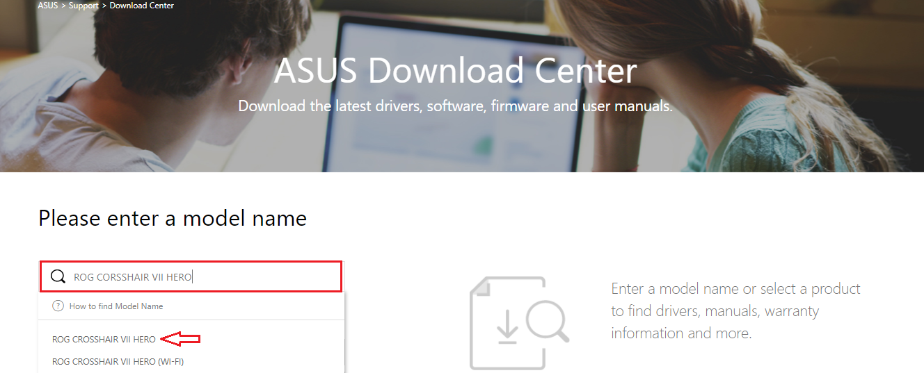
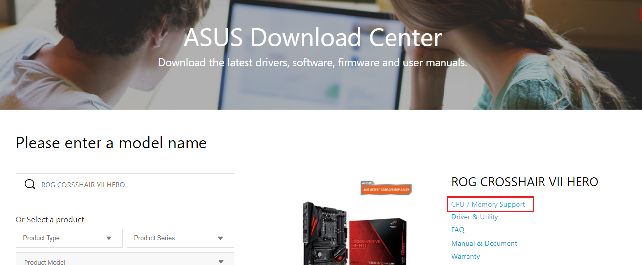
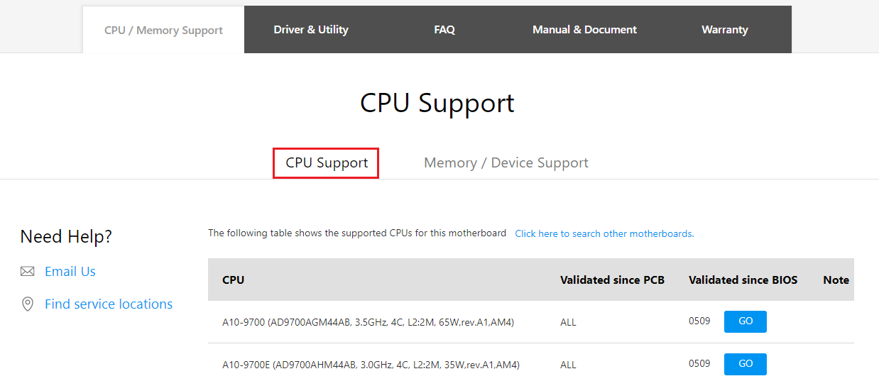
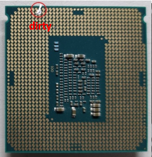
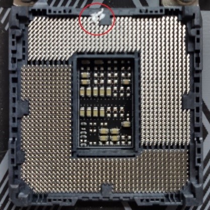
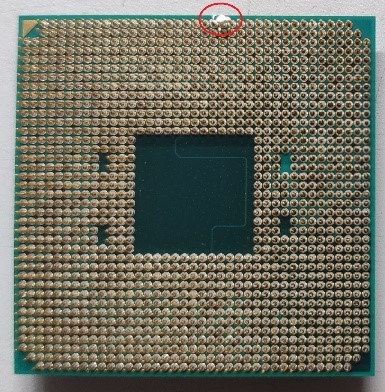
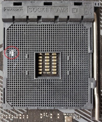
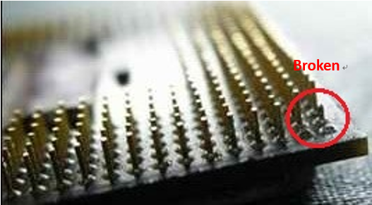
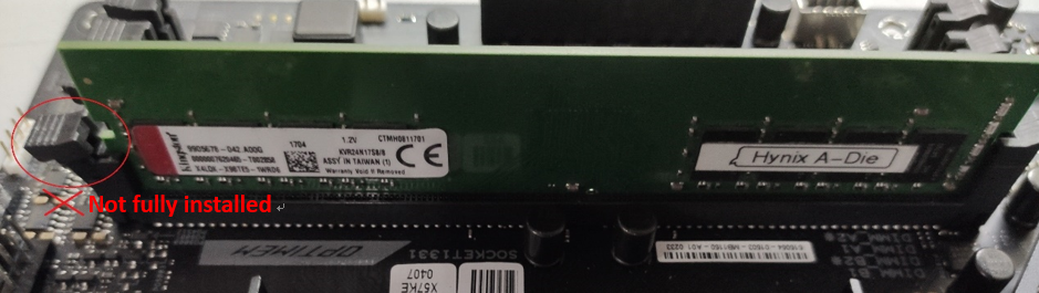
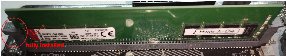
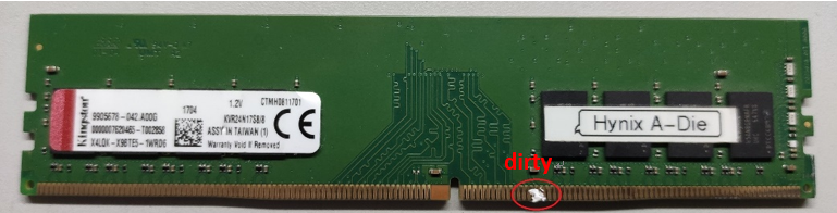
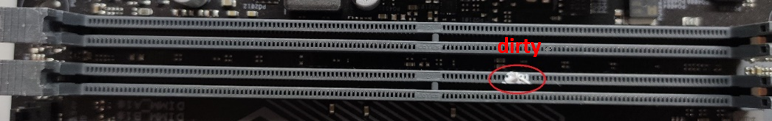
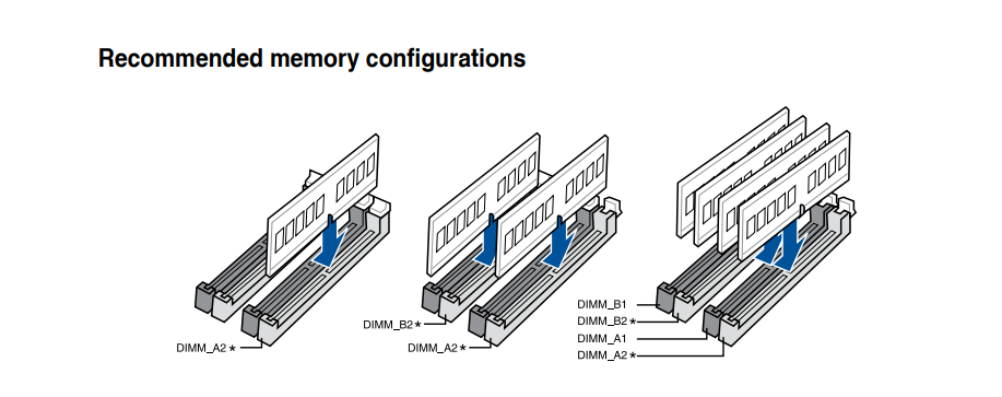
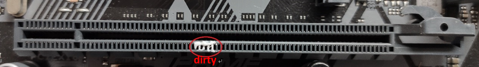
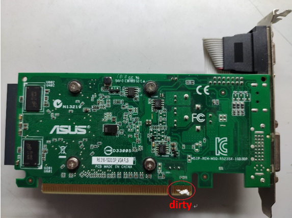

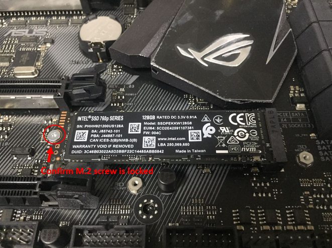
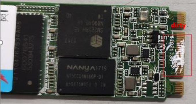
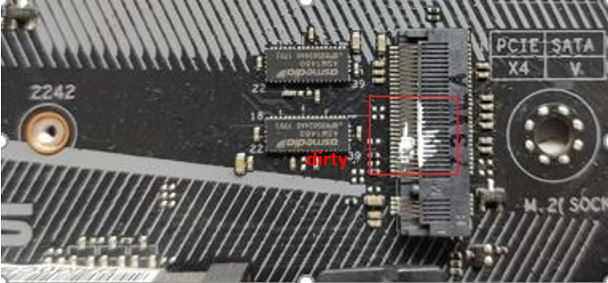
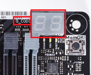
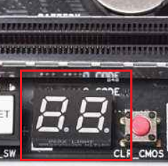
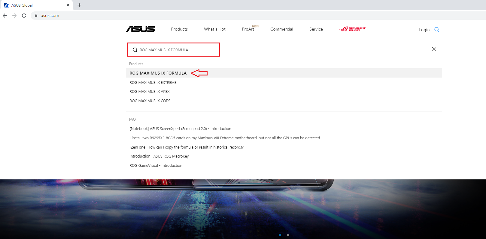
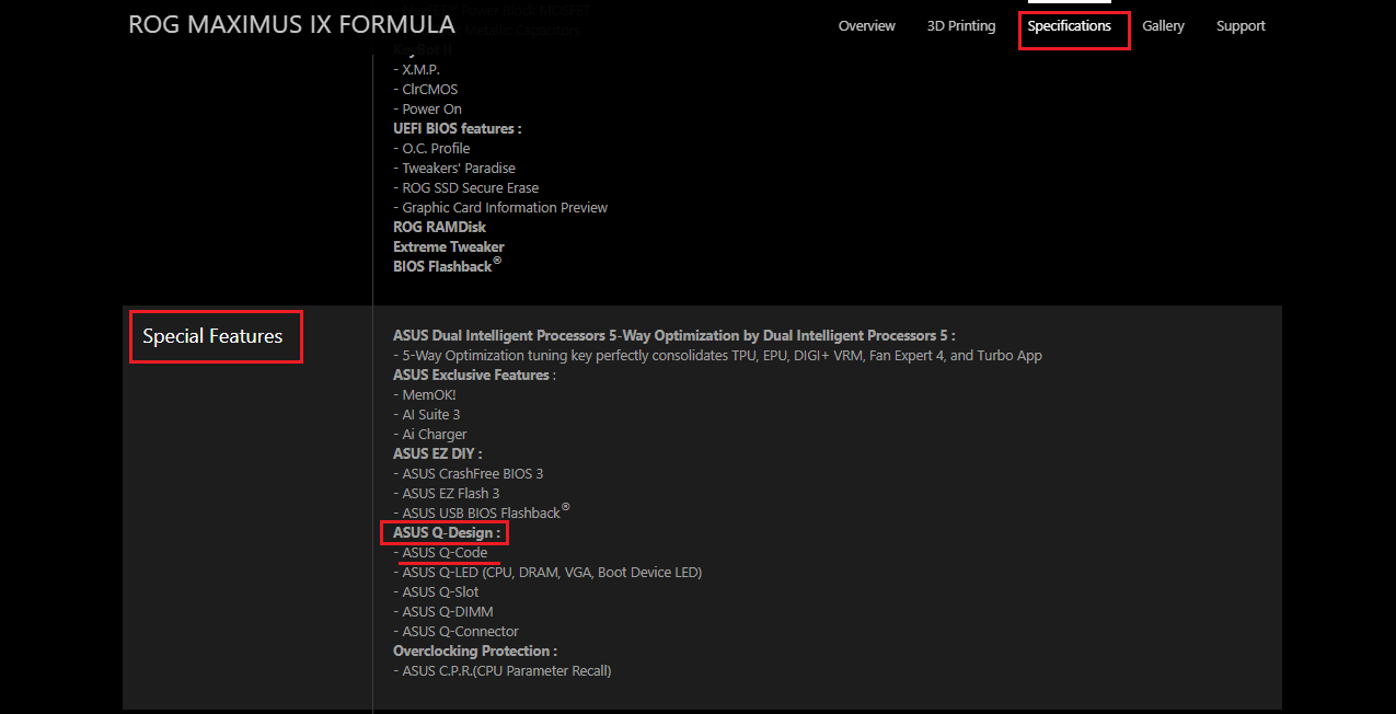
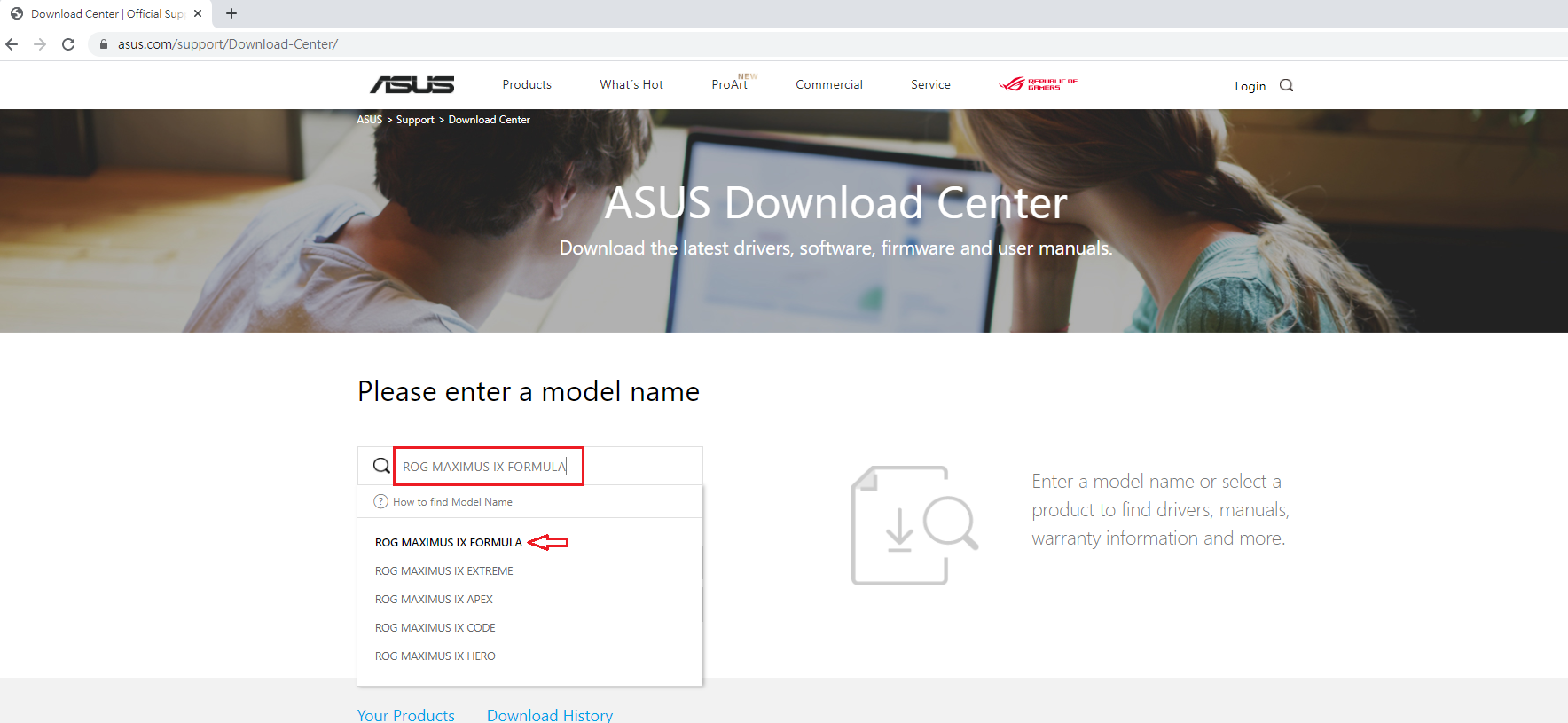
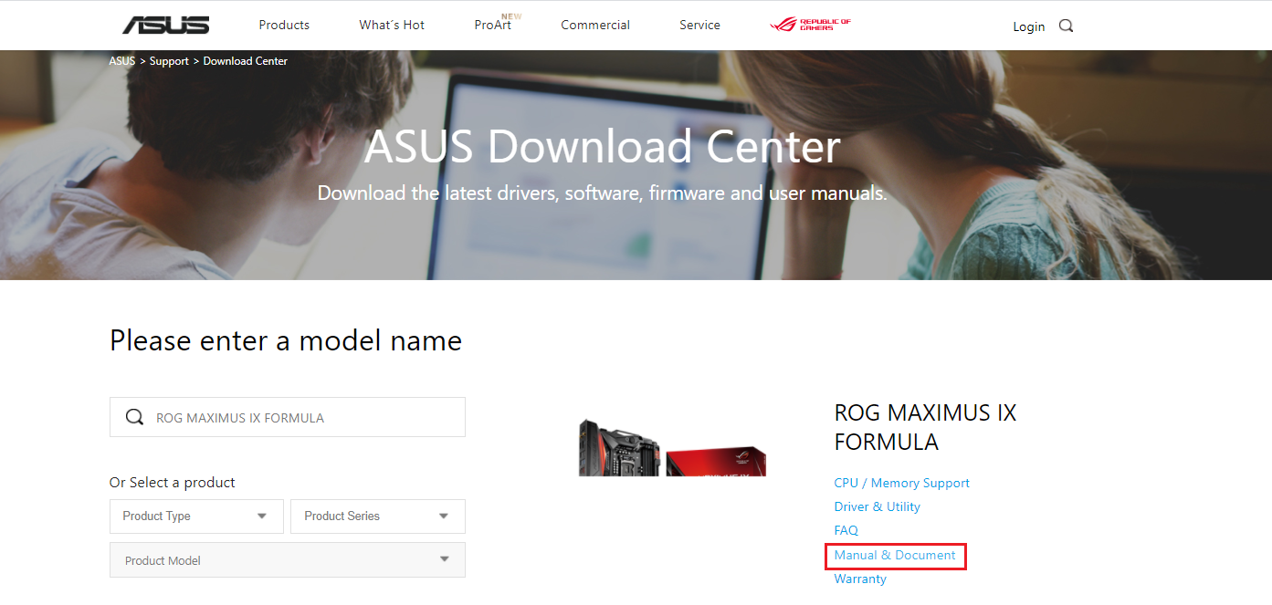
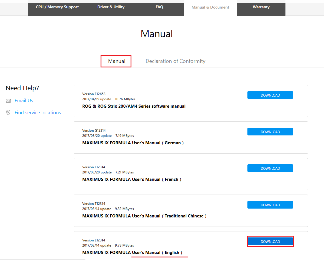
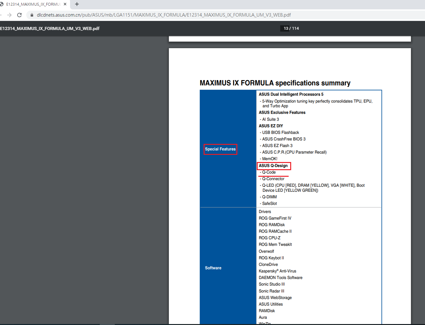


")


 Хотелось бы, чтобы дискретки вне игр сильнее спали…. ( в идеале выключались, но мне кажется они этого не умеют).
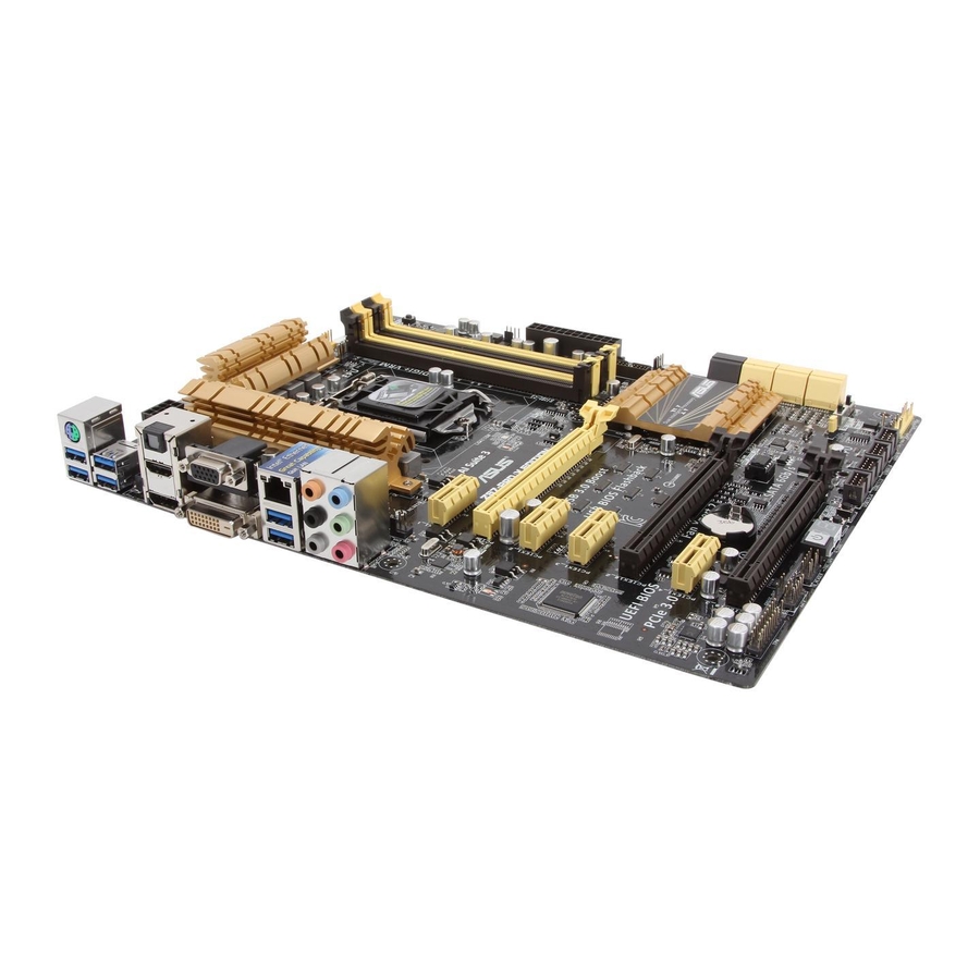
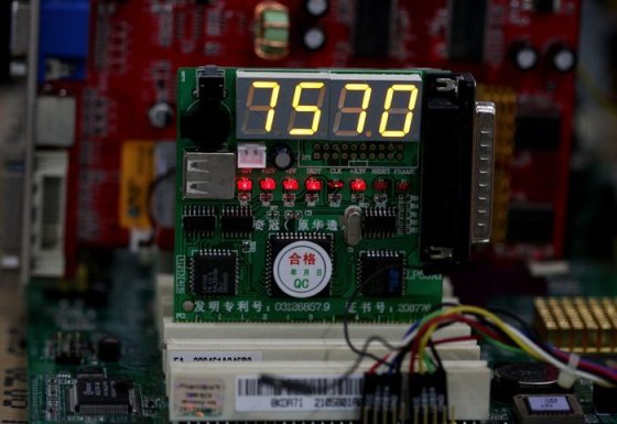


 melov
melov